Project 2_Design & Analysis of a Hostel building at Guwahati, Assam
In this project, to experience the entire design process from modelling, analysis, design, and preparation of construction drawings. The architectural drawings of a G+3 RCC building is provided. The following information on the building is to be used:
- Location – Guwahati, Assam
- Function – Hostel block in an academic institute
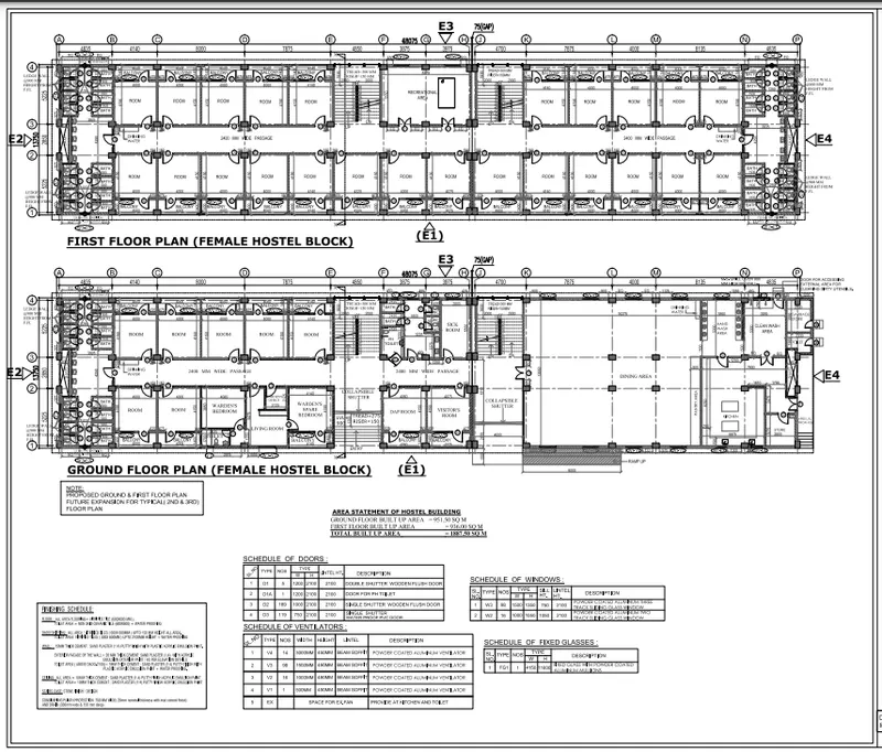
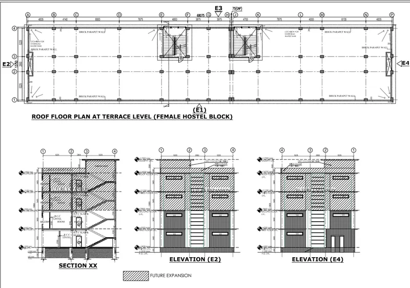
The walls will be made of AAC blocks. Other loadings are to be calculated as per the architectural drawings.
The buildings rests on type 3 soil. Piles of length 10 meters and 500 mm diameter with load carrying capacity of 280 KN is to be used.
The ground floor level will be at a height of 2 meters above existing site level to avoid flood water enter the building.
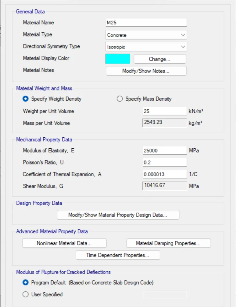
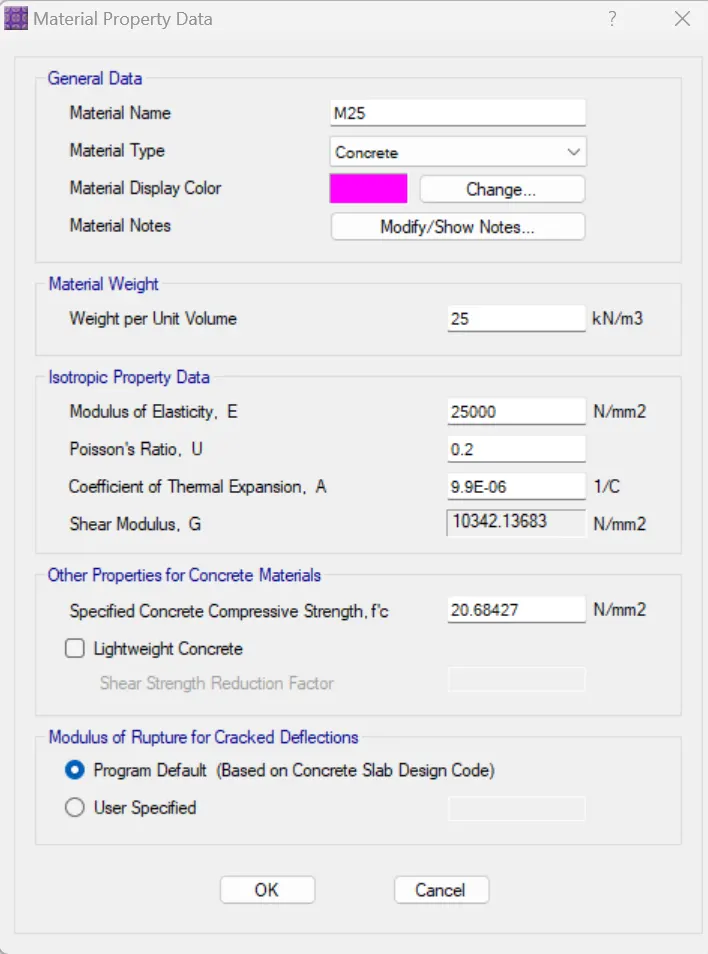
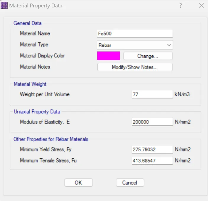
M25 grade of concrete with Fe500 for longitudinal reinforcement and Fe 415 for shear reinforcement is to be used.
The following design IS codes will be required for reference:
- IS 875 part 1
- IS 875 part 2
- IS 13920
- IS 1893
- IS 2911 part 2
- IS 456
- SP 34
Students will have to produce the following:
- Etabs model for the two blocks on either side of the expansion gap
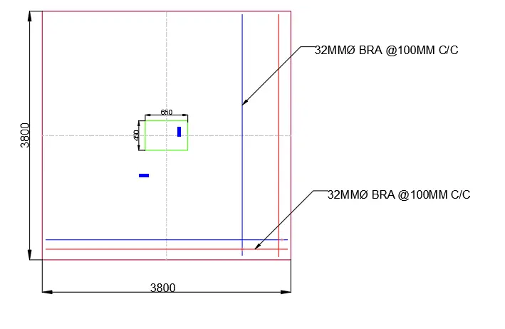
- Foundation details illustrating the pile & pile cap reinforcement
- Tie beam details connecting the pile caps
- Column reinforcement
- Framing plan for typical floor
- Beam reinforcements for ground floor
AIM: In this project, to experience the entire design process from modelling, analysis, design, and preparation of construction drawings. The architectural drawings of a G+3 RCC building is provided.
INTRODUCTION:
- To analysis and design of a given building will depend on the type of building, its compleity, the number of stories.
- The procedure of the structural design will involve some steps which will depend on the type of building and also its complexity and the time available for structural dsign.
- futher, started the structurl design, the following data of given above are required.
PROCEDURE:
- First the open the Etabs model file in it,
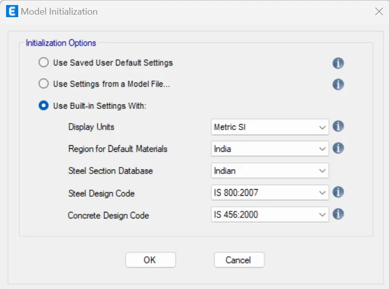
- After selecting the new model the new tab opens, then select the Use in built-in setting with options, as shown below.
- And now, setting the grid systems as per drawings data , as given above
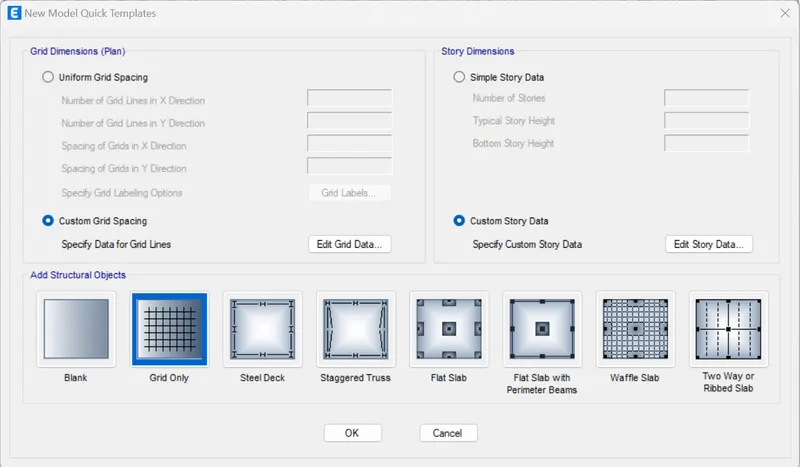
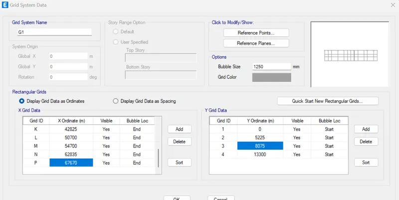
-
Next we need to add the stories upto 3 story in the story data.
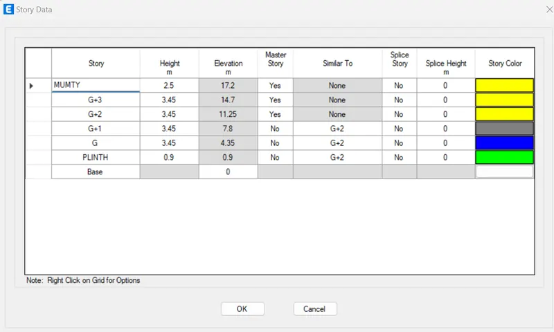
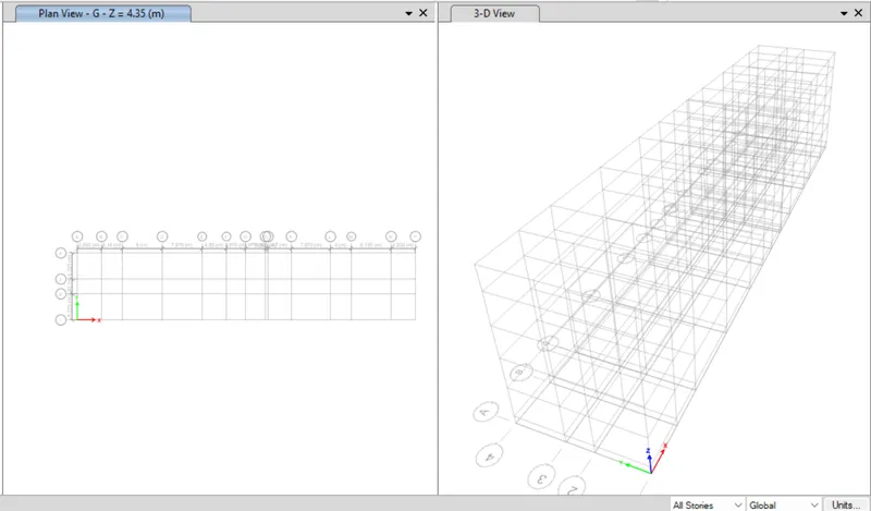
-
Next open th define option and select material properties .
-
after selecing the material by selecting the ADD NEW material options .
- Then, add material type as concrete and grade M25.
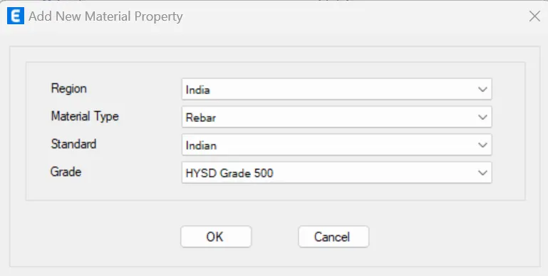
- nd add rEBAr material grade as HYSD Grade 500 and HYSD Grade 415.
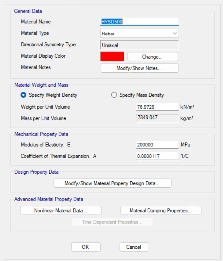
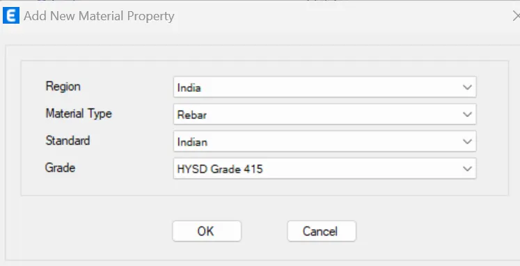
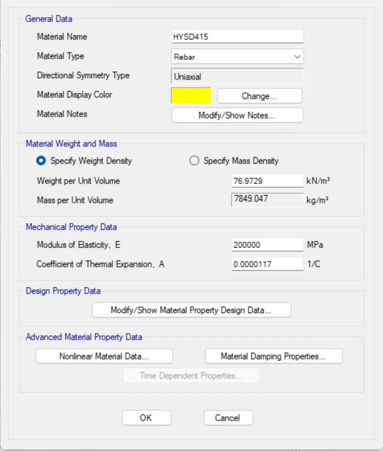
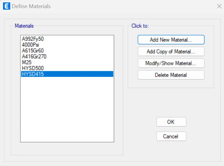
- materials are DEFINED.
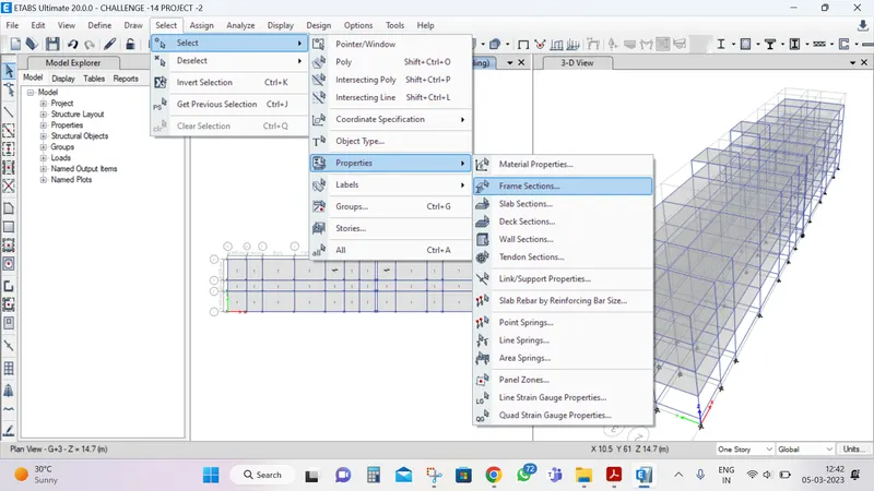
- Now, select the selection properties and click on the frame sections.
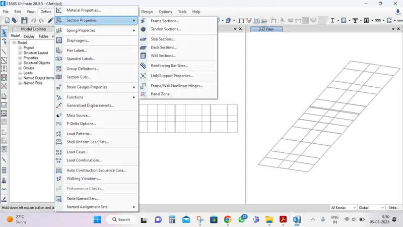
-
After, selecting the frame sections the new tab will be visible, in that we need to select the add new property,
-
Next the frame section property data, add COLUMN size 450 X650.
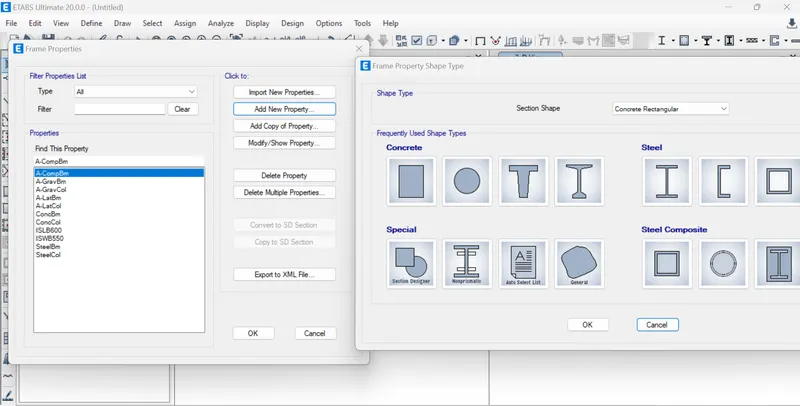
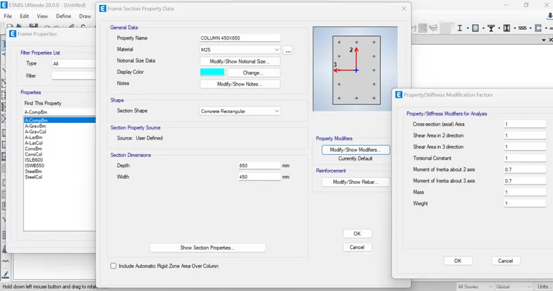
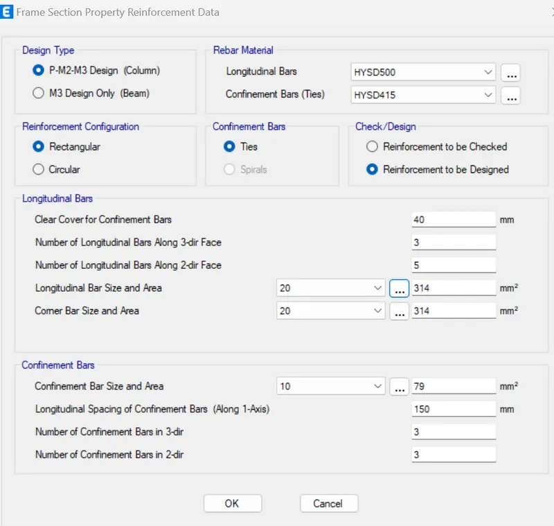
- set it and click ok.
- Then, Add the BEAM size 400X500 in the frame section property
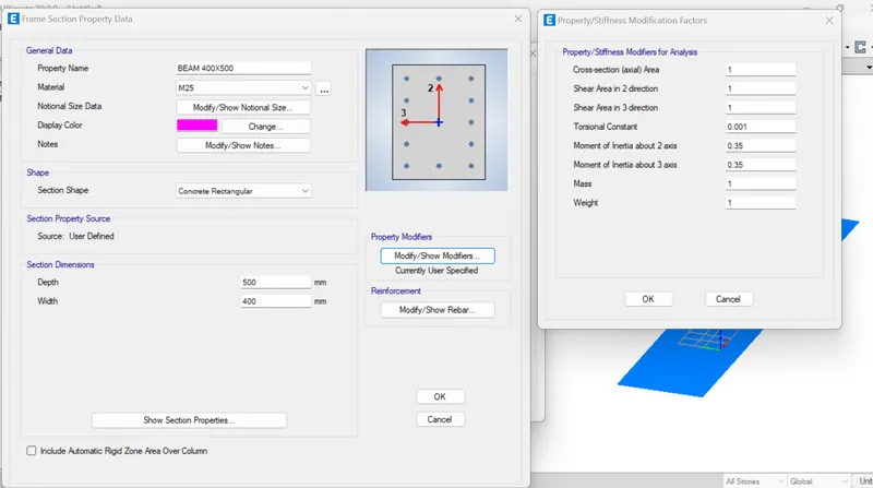
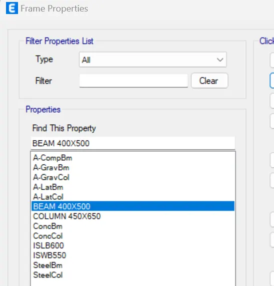
-
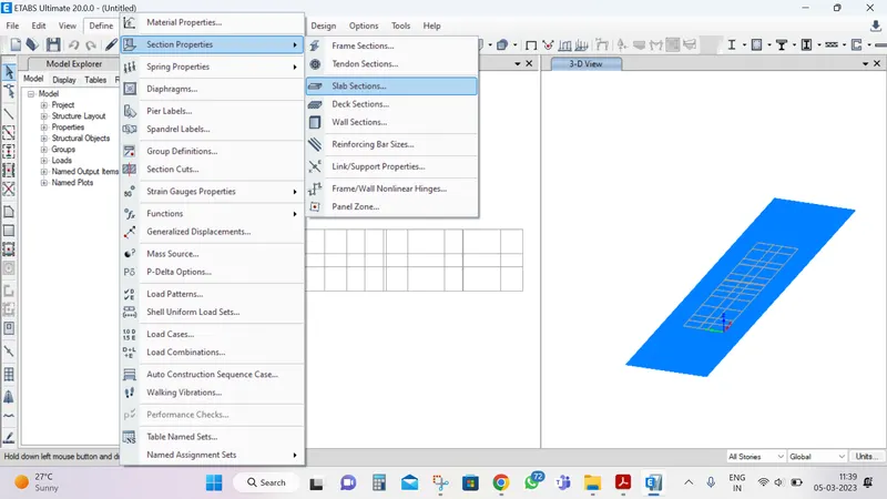
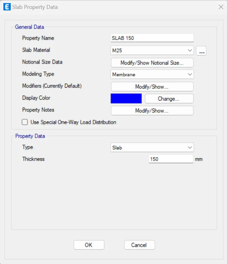
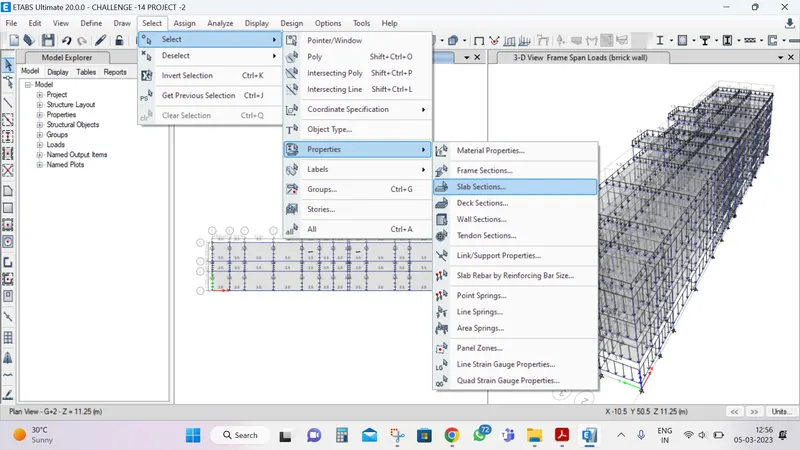
Next the select the slab selection option in selection properties.
-
set it slab 125 mm thicknes, concrete grade M25 and click ok.
-
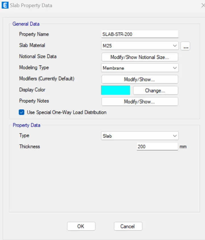
Then , again set the slab 200mm, for staircase.
-
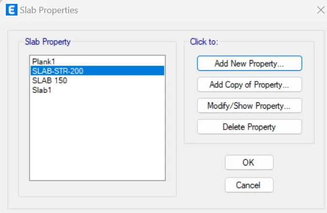
and assigned the slab properties.
- Now Assign the beam column and slab propertis, select the quick draw for column, beams, slabs/floors.
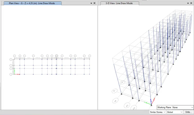
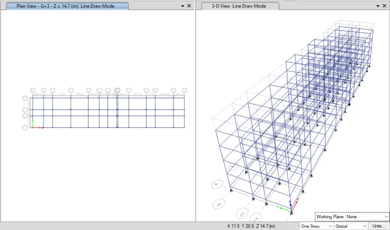
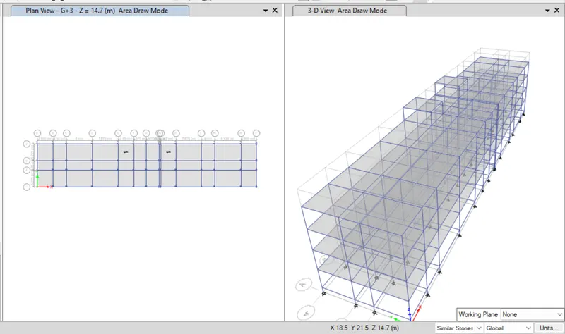
-
Now, open the base plan and select the all base joints.
-
select the Restraints from joint options, select the pinned joint and apply it.
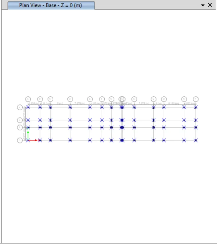
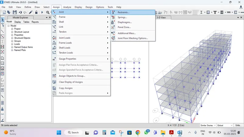
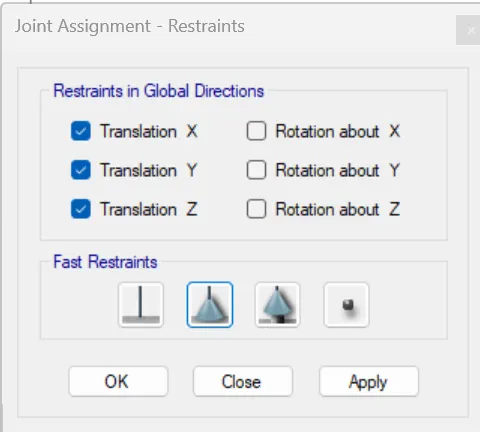
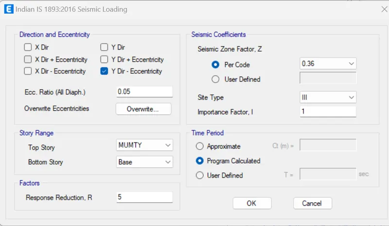
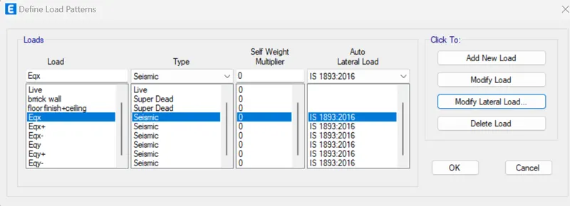
- Then, select the load patterns from the define option, and set the DEAD load, LIVE load, Brickwall load, floor finish load and seismic load .
-
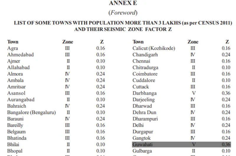
As per IS 1893:2002 . The seismic zone factor of Guwahati, Assam is taken as 0.36
-
Then, wed select the object type options as tab opens , select the floors and click on the select button and close.
-
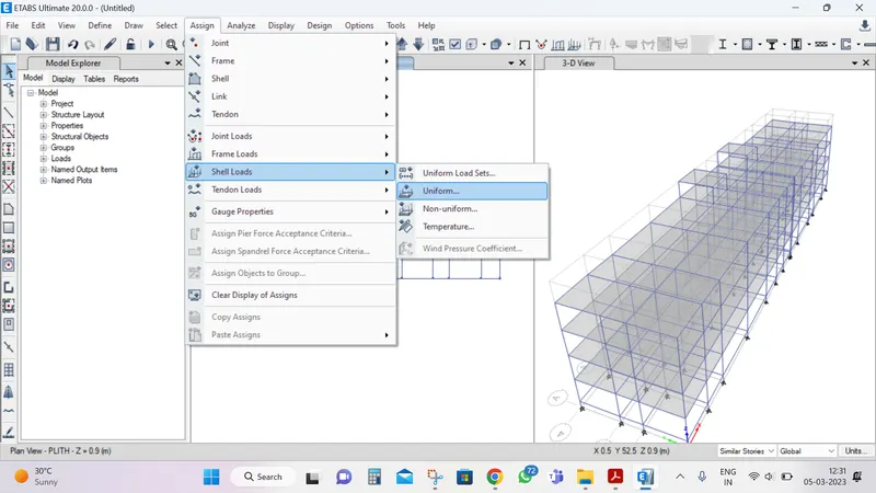
then, click assign option and select shell loads, and and select uniform options.
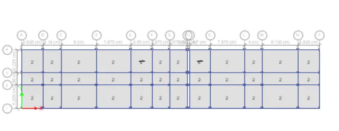
- And consider he live load upto the to 3rd floor with 2kn/m^2.
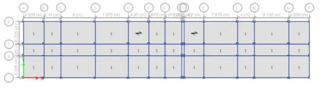
- floor fiinish
-
elect the object type option, and select the beam and click on the selec the button close.
-
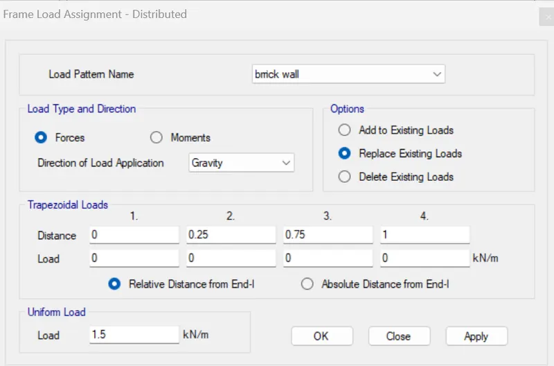
now, assign option and then select the frame load, from the frame load and select the Distributed options.
-
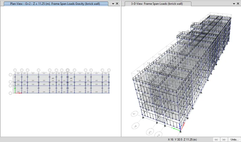
Then, the after the new tab will appear, and load pattern as Brickwall and take uniform load as 3.5 kn/m, and click ok.
-
-
-
No, we NEED SEE the mass source will be assigned.
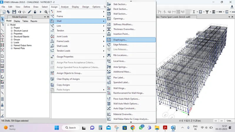
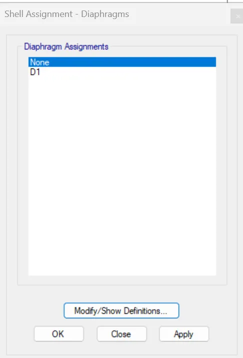
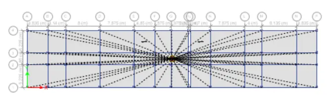
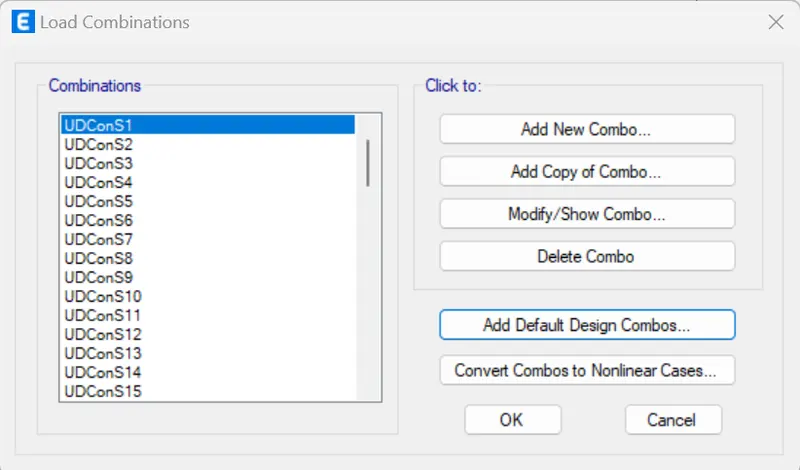
- define Load Combinations
- Now, start the beam and column design , selecting the Start design/check option. and Run analysis

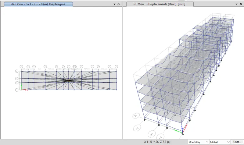
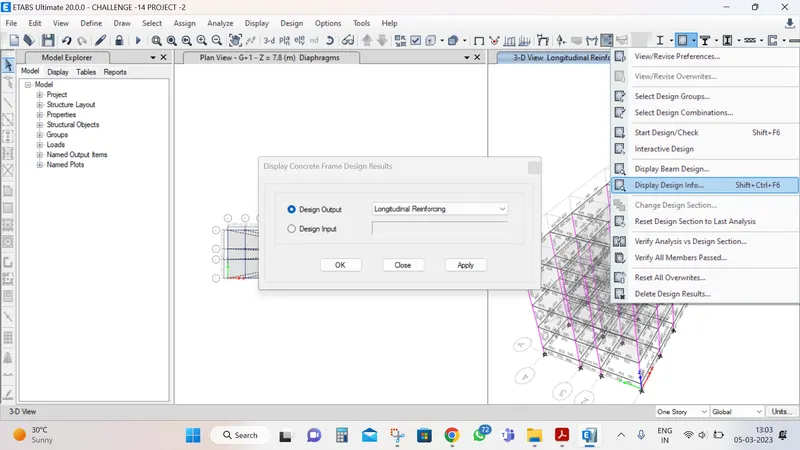
- Then displayed it output.
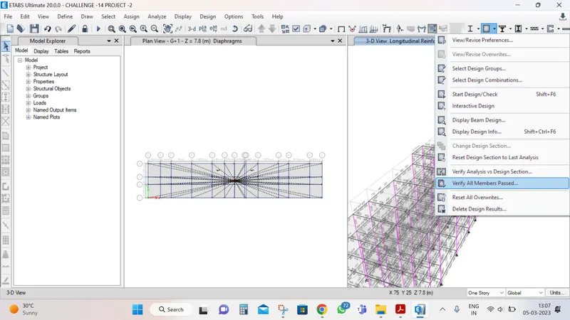
- verify the menbers passed or not
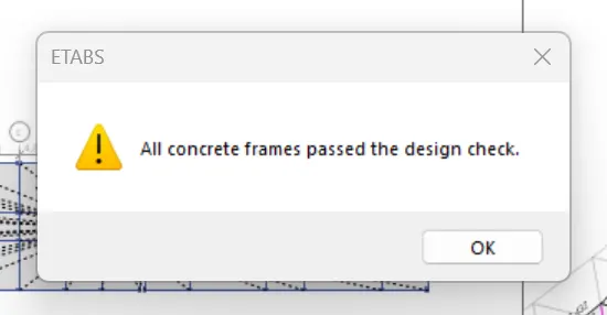
- all members are passed
Then the details will appear.
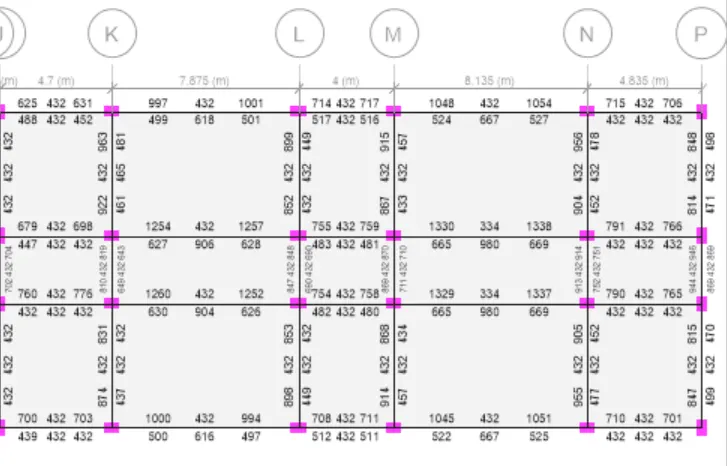
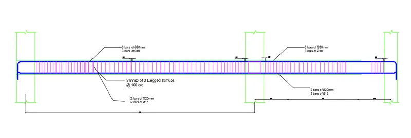
- Next the draw Reinforcement diagram of 6 span continuous beam along grid-3 and provide the reinforcement details.
- The maximum Ast For the bottom support is 669mm^2 and bottom middle is 980mm2.
- The maximum Ast For the top support is 1338mm^2 and top middle is 432mm2.
- Now , we provide 3-20 and 3-16 dia at thr top and bottom is 20-2 and 16-2 ,
- Then provide 3-16 dia at the top supports for the continuous beam .
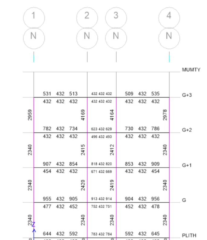
Now, we see the detail of column reinforcement.
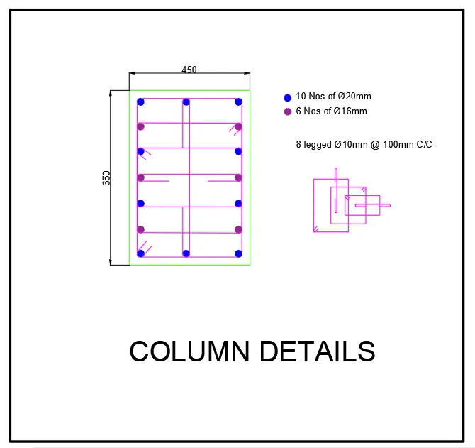
- size 650 X 450mm
- The maximum Ast of the column is 4169 mm^2.
- Provide !0nos od 20mm dia and 6 nos of 16mm Dia
- details of shear reinforcement are provide as per speciaql confining reinforcement provision of clause 8.1 of IS 13920-2016.
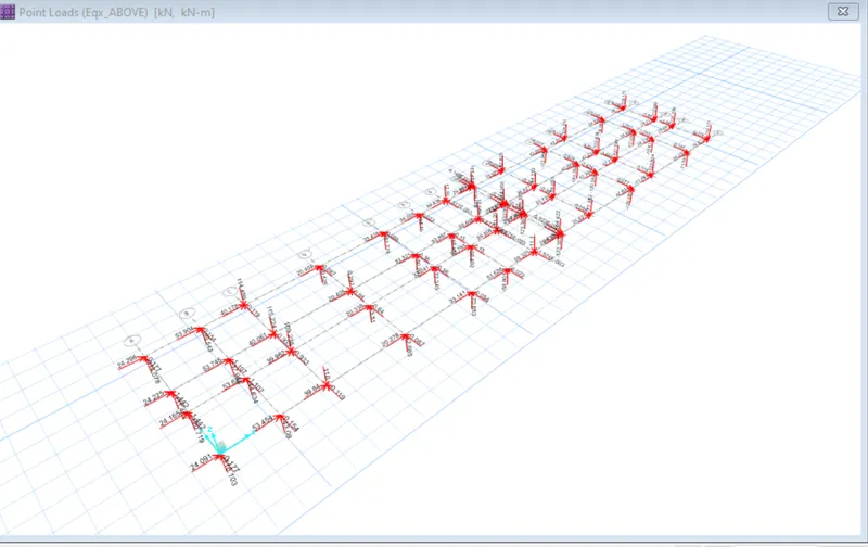
Hence the design is completed. Now, we need to export this Base reactions and load conditions in f2k format for footing design using SAFE software
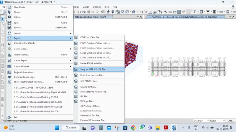
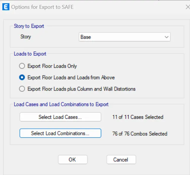
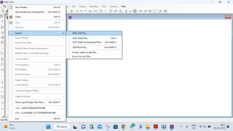
- Now, import the safe f2k file into the SAFE software. Hence all the reactions and loads have been imported to the software.
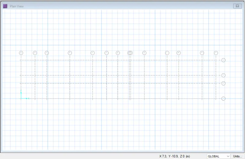
- Check the loads are availble or not
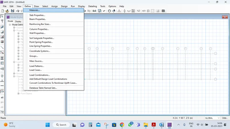
- Define the materials for concrete and rebars.
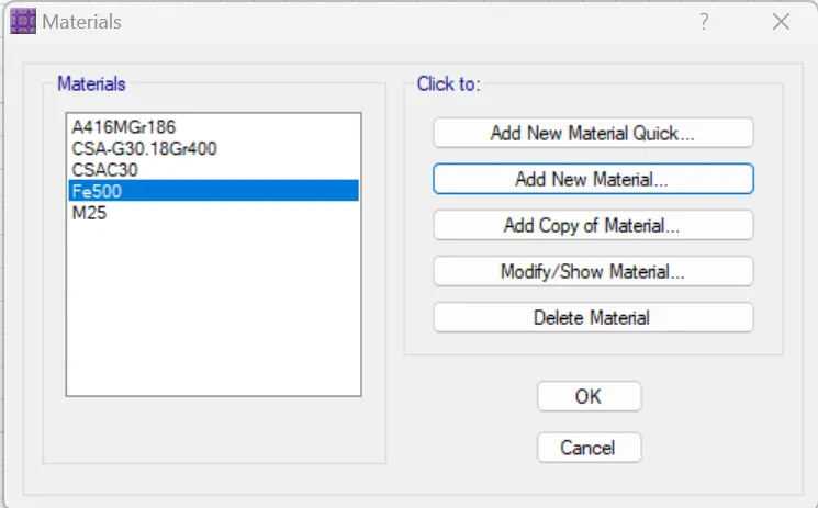
- Define slab properties.
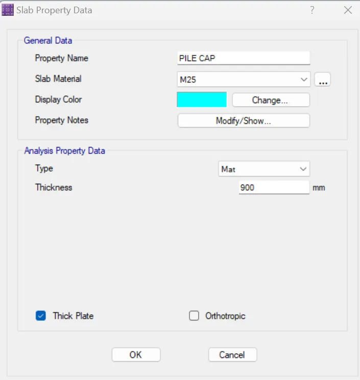
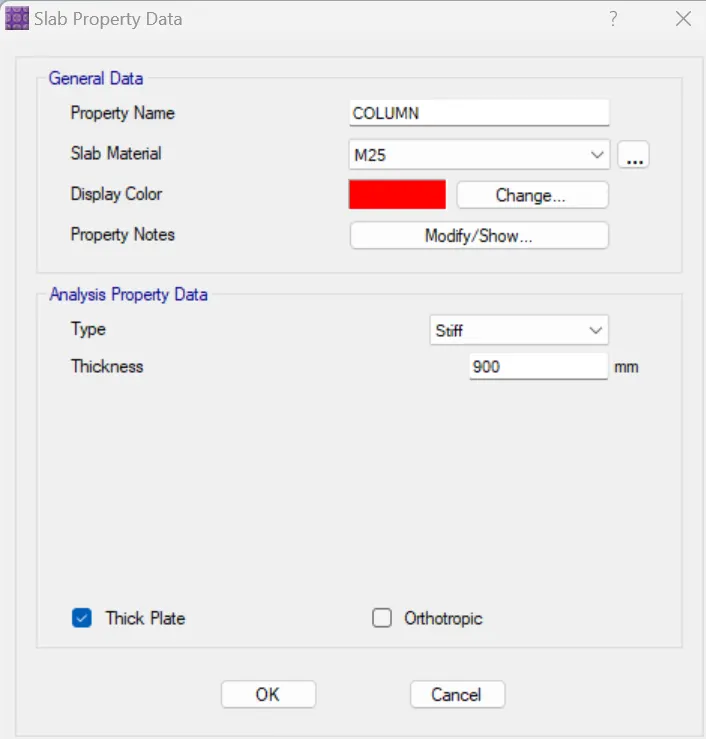
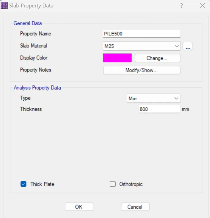
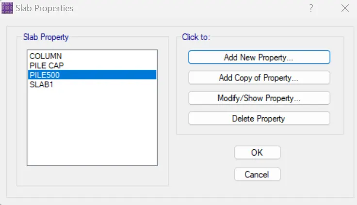
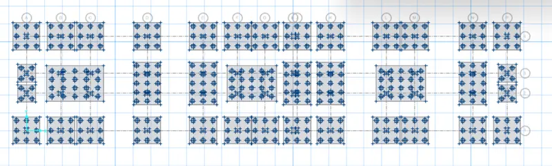
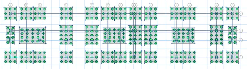
- After that using draw point option drop the points for footing for each column.
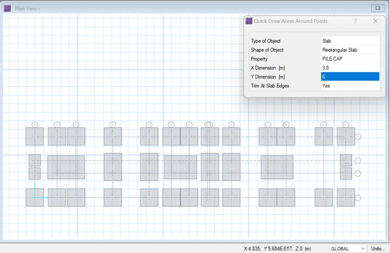
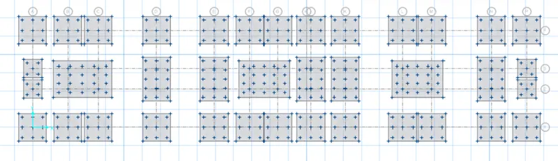
- Now, go to draw option and draft points on footing for the piles to be developed.
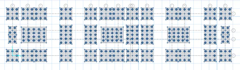
- Next we need to provide pile, using the above used option and material property as pile500.
- Then place, the column along grid intersections.
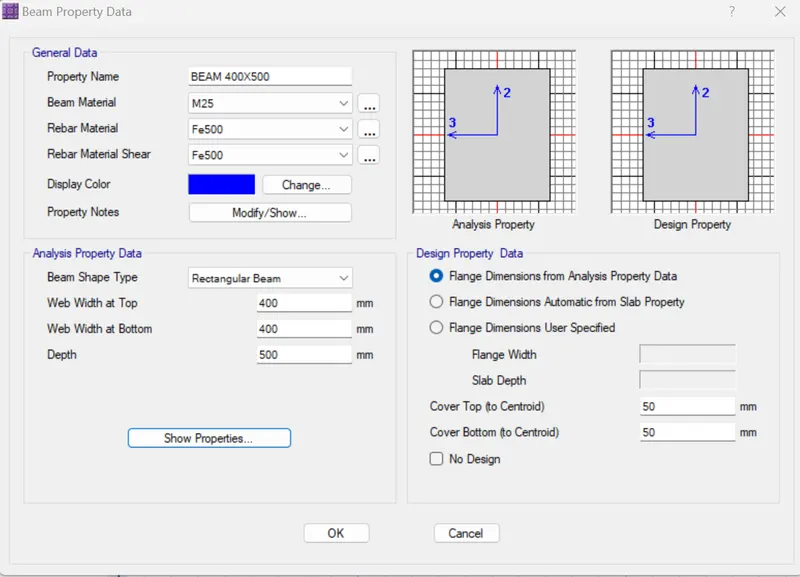
- Define beam for tie beams.
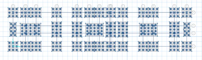
- Now, we have to assign springs at these locations where piles are placed.
- For this we need to calculate the spring constant.
- Spring constant= `(AE)/(L)=196346.5⋅25000/10000=490873N/(mm.`
Then assign this spring constant. 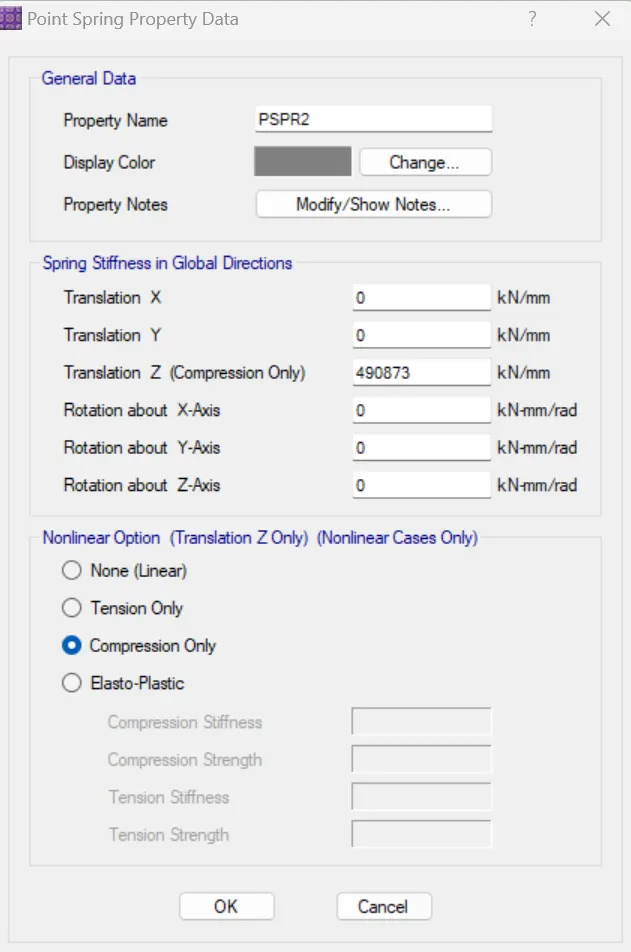
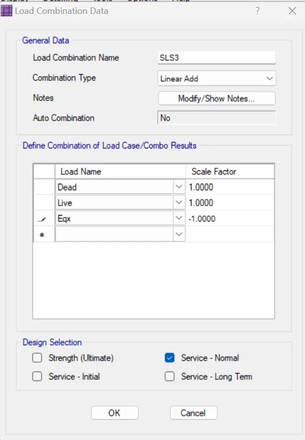
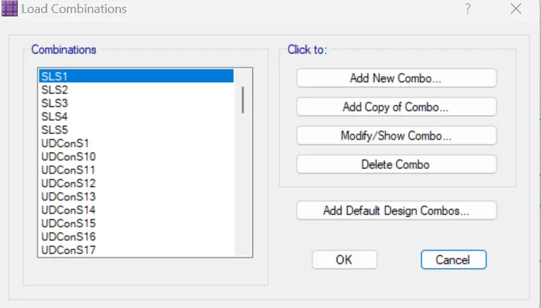
- Now, define the load combination for serviceability limit and ultimate limit.
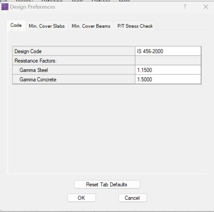
- Next, we need to check the design result.
- Displacement values are within the limit, hence safe.
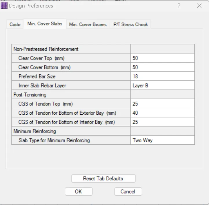
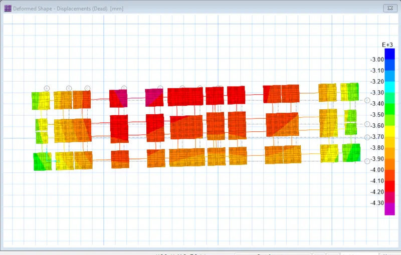
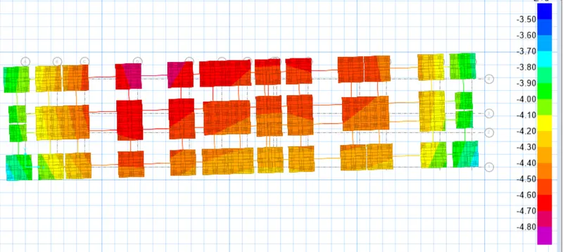
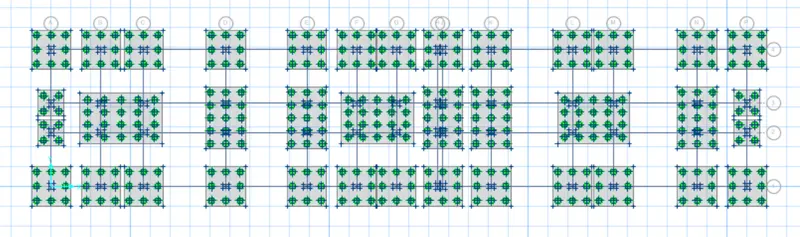
- Reaction check :
- Now, we need to design the strip.
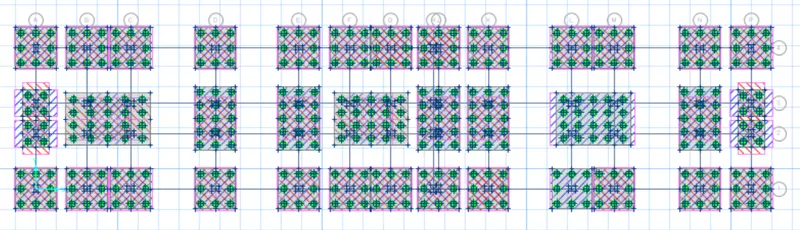
- Now, again carryout the design.
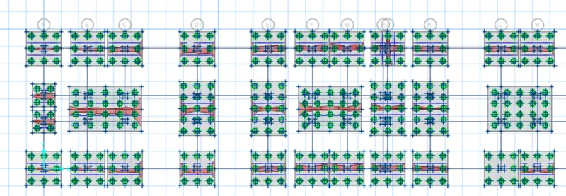
- For strip layer A
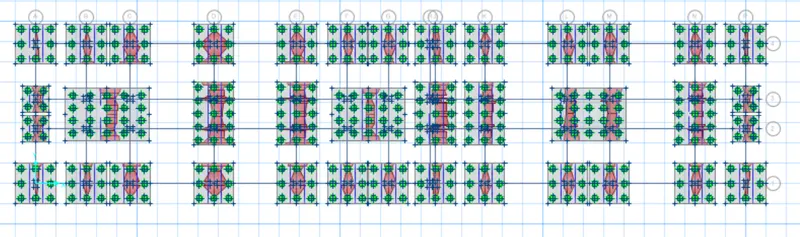
- For strip layer B
- Hence, the design of footing is completed.
- The reinforcement drawings associated with the design is given below: