Project 2_Design & Analysis of a Hostel building at Guwahati, Assam
Aim - To carryout modelling, analysis, design, and preparation of construction drawings of a G+3 RCC building situated in Guwahati Assam.
Procedure -
Step 1)
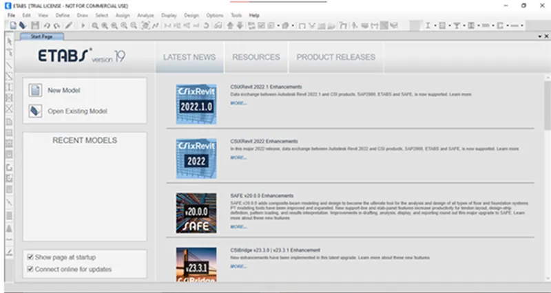
i) Open the Etabs software from deskstop icon
ii) Once software is open - Click on New model
Step 2)
i) Once you click on New model
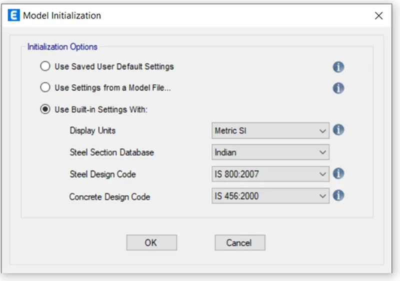
ii) A Model Initialization setting will open
iii) Select - Metric SI units
iv) Select section database - Indian
v) Select Steel code - IS 800-2007
vi) Select Concrete design code - IS 456-2000
Step 3)
i) Once you click Okay
ii) A following dialog box of grid settings will open
ii) In New Model Quick templates under grid dimensions select the custom grid spacing
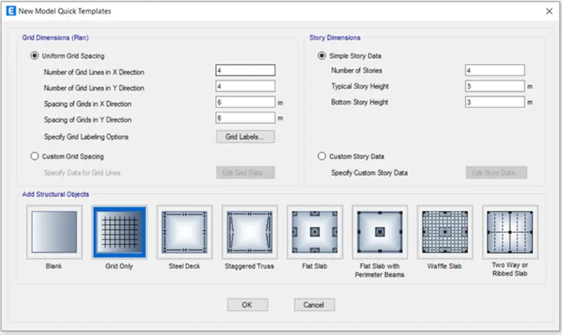
iii) Once you click on Custom grid spacing
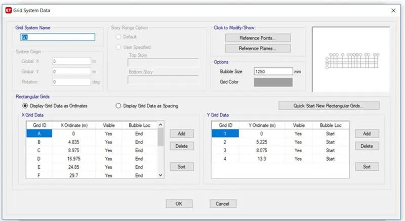
iv) Click on Display grid data as spacing
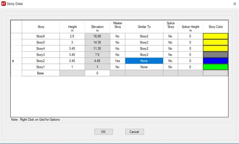
iii) Now input the storey details
iv) As given in question and Story 1 was selected as the Master story
v) Click on Okay.
Step 5)
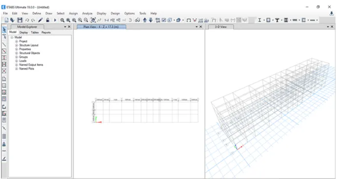
i) Once you click on Okay
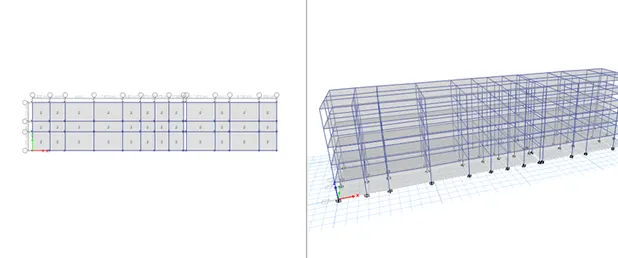
ii) A plan and 3D view of model is created in model space
Step 6)
i) Now we have to define the materia properties
ii) Click on Define
iii) Click on Material properties
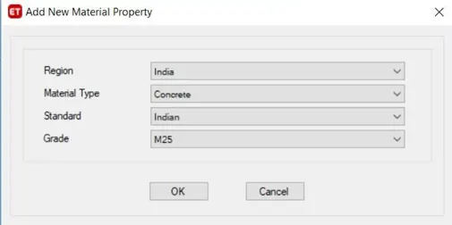
iv) Add New material as Concrete
v) Select Grade of concrete - ...........................( given)
vi) Standard as Indian
vii) Click on Okay.
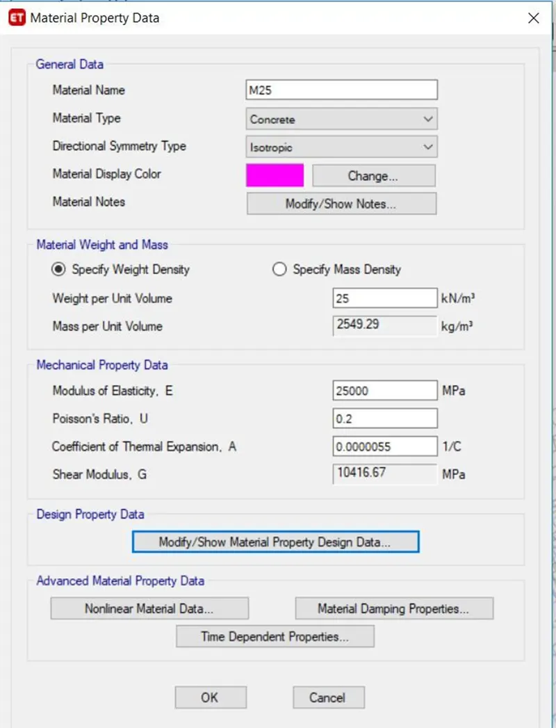
viii) Click on okay
ix) The remaining data is as per IS code
i) Similarly we have to define the materia properties for Steel
ii) Click on Define
iii) Click on Material properties
iv) Select New material as Rebar
v) Select Grade of Steel - HYHD - Grade Fe415...................... ( given)
vi) Standard as Indian
vii) Click on Okay.
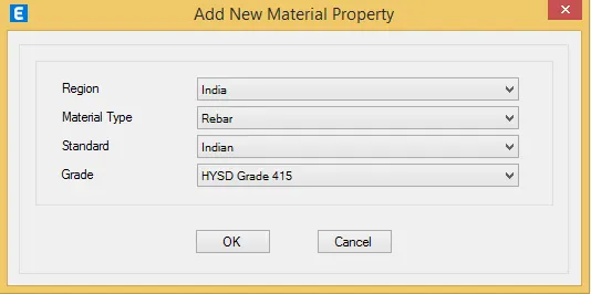
viii) Click on Okay
ix) The remaining data is as per IS code
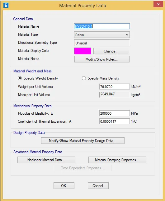
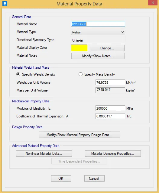
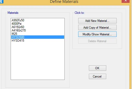
x) Material properties is added
Step 8)
i) Now we have to Define the section properties ( Column and Beam )
ii) Click on Define
iii) Select - Section properties
iv) Click on Frame Section
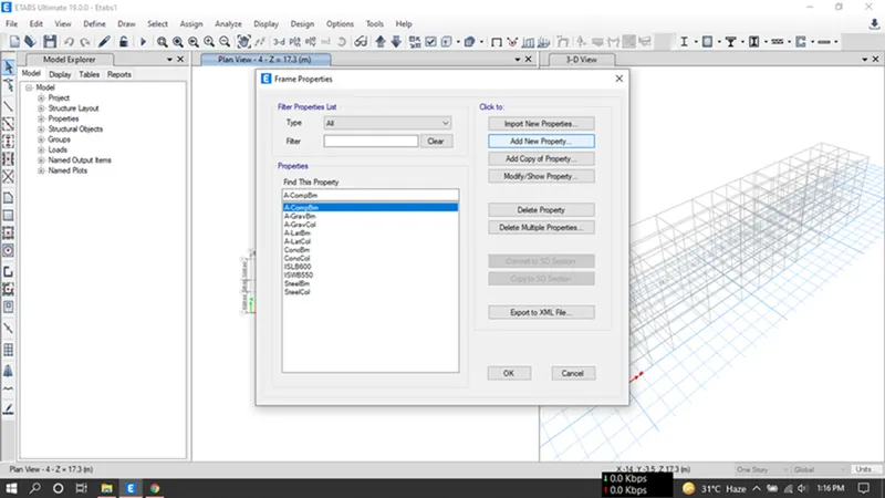
v) Click on Okay.
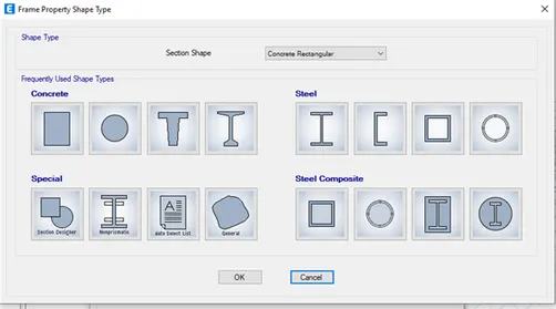
vi) Click on Add new property
vii) Select Rectangular shape
vi) Give property name - Beam 400x500............( given)
vii) Material type - M25
viii) Section Shape - Concrete Rectangular
ix) Depth - 500 mm
x) Width - 400 mm
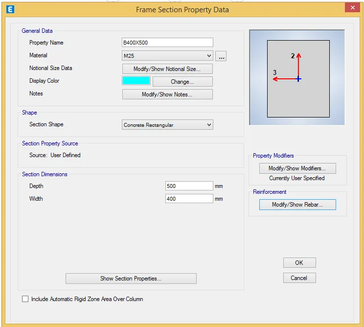
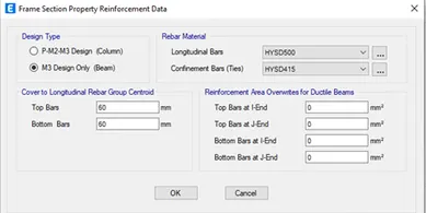
xi) Click on Modify / show Rebar
xii) Select M3 Design Only (Beam)
xiii) Select the rebar materials as HYHD Fe415 in both the direction
xiv) Click on okay.
xv) Similarly we have to follow the same steps for Column also.
xvi) Property name - Column 550 x 550 mm
xvii) Material - M25
xviii) Depth - 550 mm
xix) Width - 550 mm
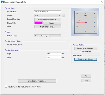
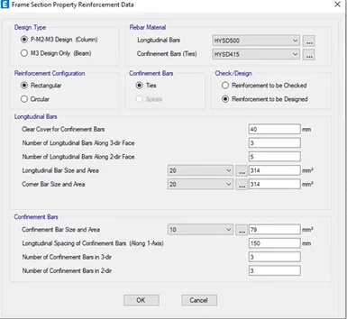
xx) Click on Modify / show Rebar
xxi) Select M3 Design Only (Column)
xxii) Select the Rebar materials as HYHD Fe415 in both the direction
xxiii) Click on okay.
Step 9)
i) Now we have to define Slab properties
ii) Click on Define
iii) Select Section Properties - Select Slab properties
iv) Click on Slab Section
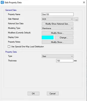
v) Give property name - Slab 150
vi) Slab material - M30
vii) Modeling Type - Membrane
viii) Type - Slab
ix) Thickness - 150 mm
Step 10)
i) Now we have keep the 3D view also to see the properties
ii) Now we have to add the columns and beams
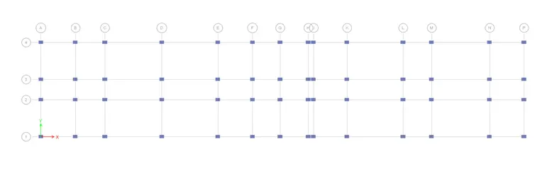
iii) Click on Quick Draw Column option
iv) Select the Column properties which we have defined earlier
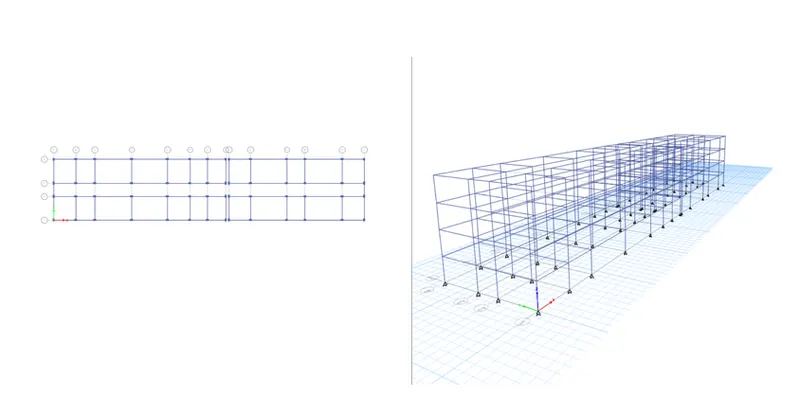
v) Draw the columns at the grids as shown in below
vi) Note that - All stories option should be selected which is at the Bottom
vii) Similarly we have to draw beams also
viii) Select Quick Draw Beam option
ix) Select the Beam properties which we have defined earlier
x) Draw the beam as shown below
Step 11)
i) Now we have to add the slabs
ii) Select Quick draw floor
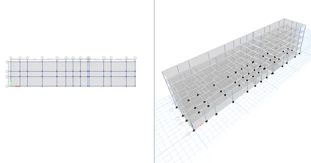
iii) Draw the slabs as shown below
Step 12)
i) Now we have to assign the loads
ii) Select Define
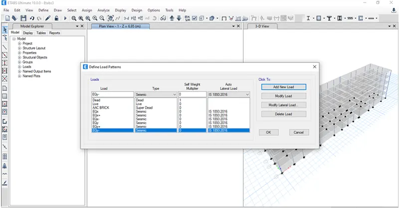
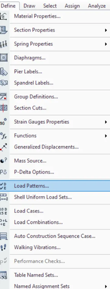
iii) Click on load patterns
iv) Define load pattern dialogue box will open
v) Add the Following loads and Select the IS code for Seismic Case as IS -1893
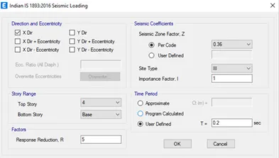
iv) The direction and eccentricity were selected as the X direction
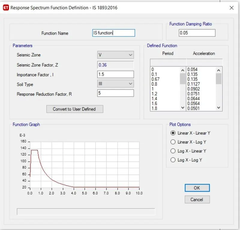
v) The Response Reduction Factor R was taken as 5
vi) Seismic zone is 5 so Z=0.36
vii) Soil type was taken as III
viii) Importance factor for residential building with less than 200 is taken 1 and time period is taken as 0.2
Step 13)
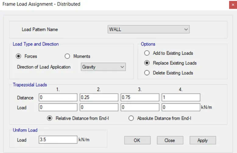
i) Now we have to assign the loads to the strucure -
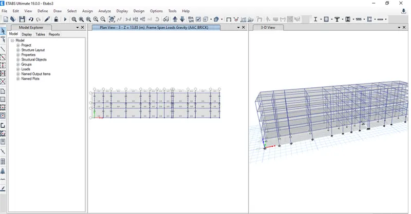
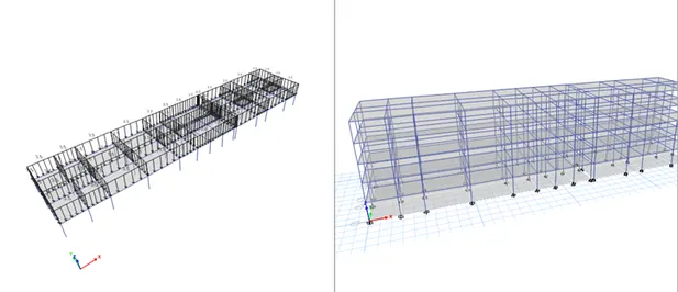
1) AAC block load - 3.5 kn/m2
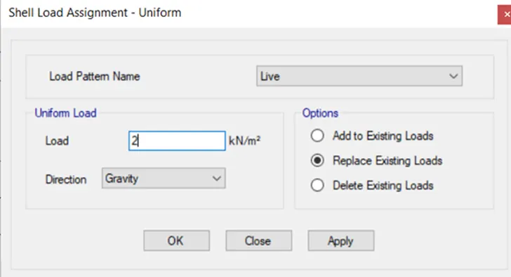
2) Live loads were applied to slabs next.
i) As per IS 875 in residential buildings its 2kn/m^2 for rooms and
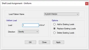
3) Floor Finish
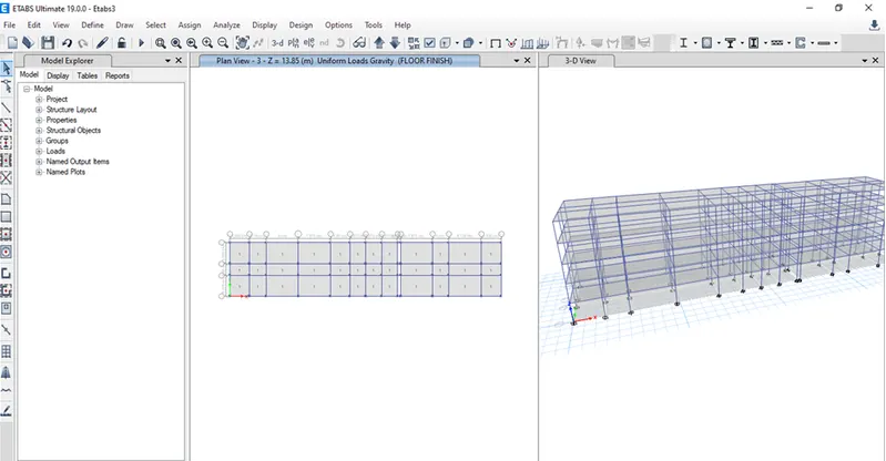
i) In the same way select slabs to assign floor finish which is 1 Kn/m^2
Step 14)
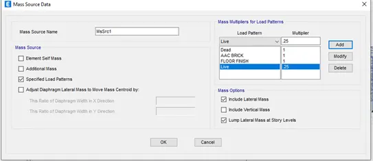
i) Now we have to assign Mass source
ii) For that Define menu- mass source options to open the mass source dialogue box.
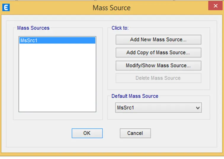
iii) Now select Modify mass source data option and click OK
iv) Now mass source datawas provided as shown and load patternwas also added to it.
v) For live load upto 3Kn/m2 - we have to assumed some fraction of live load i.e 25%
Step 14)
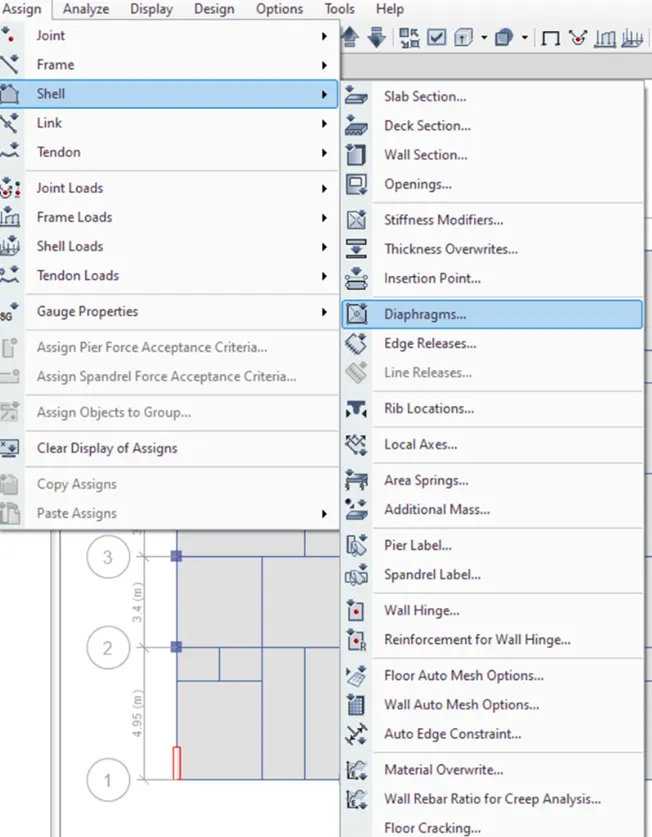
i) Now we haev to assign diaphragm
ii) In assign menu select Shell followed by Diaphragm to open the shell Assignment diaphragm dialogue box
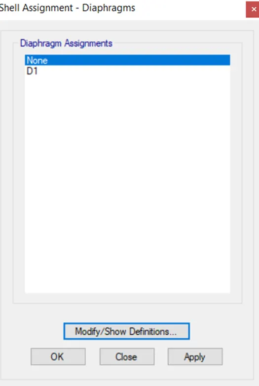
iii) Select D1 from the diaphragm assignments and click apply followed by OK.
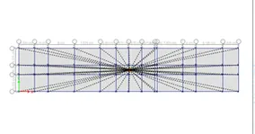
The Diaphragm D1 is applied and is as shown below.
Step 15)
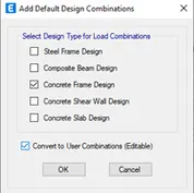
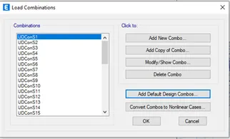
i) Now we have to add the load combinations
ii) Click on Add default Design Combo
Step 16)
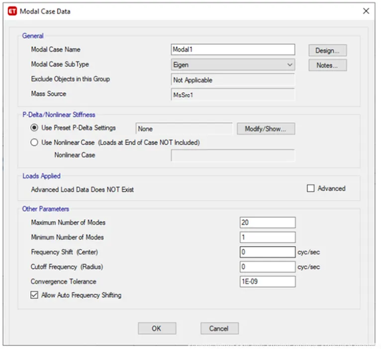
i) Now we have to create a Modal analysis
ii) For that define tab- modal cases- and select modify
iii) Enter the data’s as shown in image. Maximum number as 20.
Step 17)
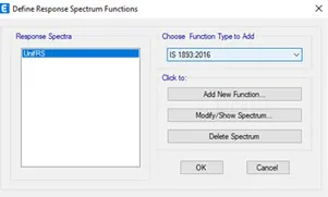
i) New function was defined as per the IS 1893 for response spectrum analysis.
ii) After selecting the response spectrum the new tab is visible,
iii) In that we choose IS 1893:2016 from the "Choose function type" and click on the Modify /Show option as shown below
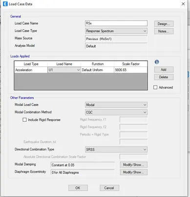
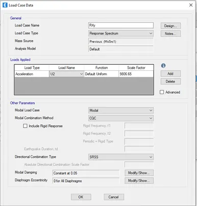
iv) Two load cases was defined for response spectrum analysis and set default scale factor initially
Step 18)
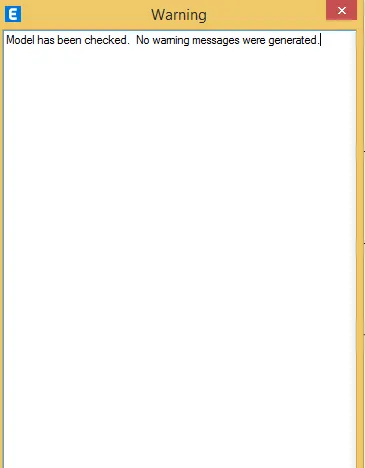
i) Now we have to check th emodel for errors, go to Analysis tab and select check model.
Step 29)
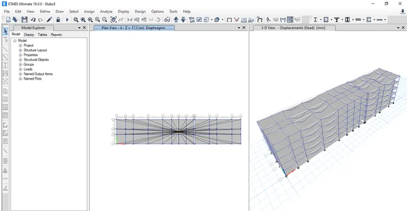
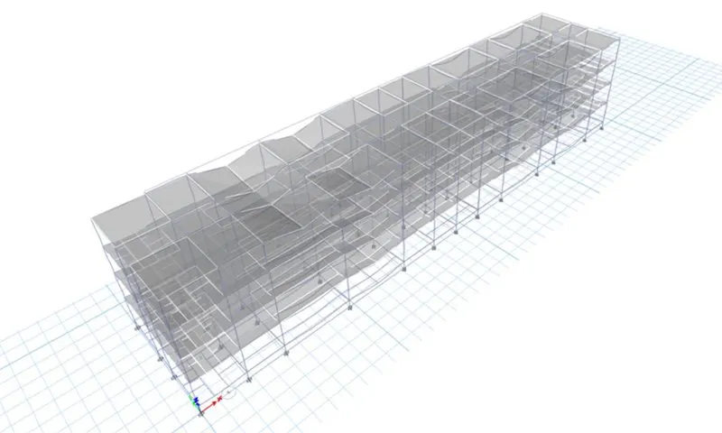
i) Now Run the model
ii) Click on Run Analysis
'
Step 20)
1) Modal Participation ratio -
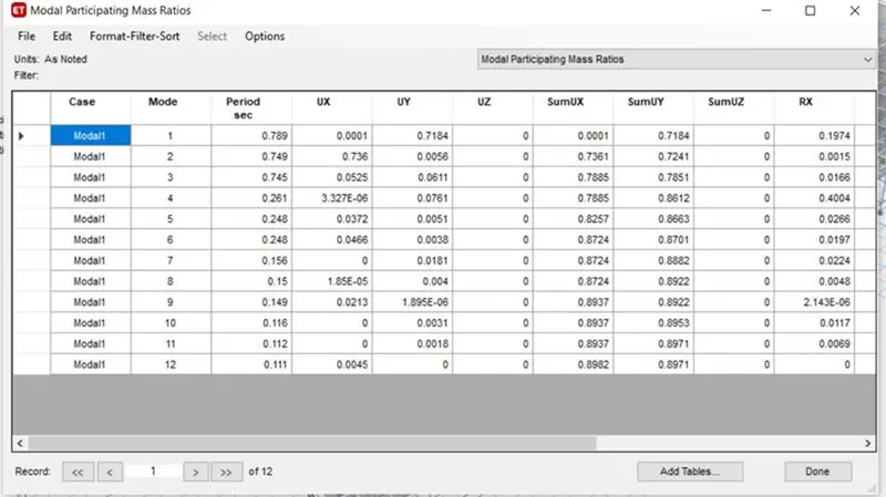
i) Modal number check for that go to Display-Show Tables-Analysis Results-Structure Output-Modal Information-Modal mass participation ratio.
ii) According to IS 1873 clause 7.1, the natural period corresponding to fundamental torsional mode of oscillation should not be greater than sum of two fundamental translational mode of oscillation (Tx+Ty>Txy)-from table 0.789+0.749=1.534>0. 745. hence no torsional irregularity.
iii) IS 1873-clause 7.1, table 6 the first three modes contribution should be more than 65% of mass participation factor in each principal plan direction. Here it is 0.71>0.65.
iv) Here Tx=0.789 and Ty=0.749, differ by 4%, hence conclude that building is irrregular in mode of oscillation in two principal plan direction.
From modal number, maximum required is 13 number as it captures more than 90% of mass in all 6 degrees of freedom.
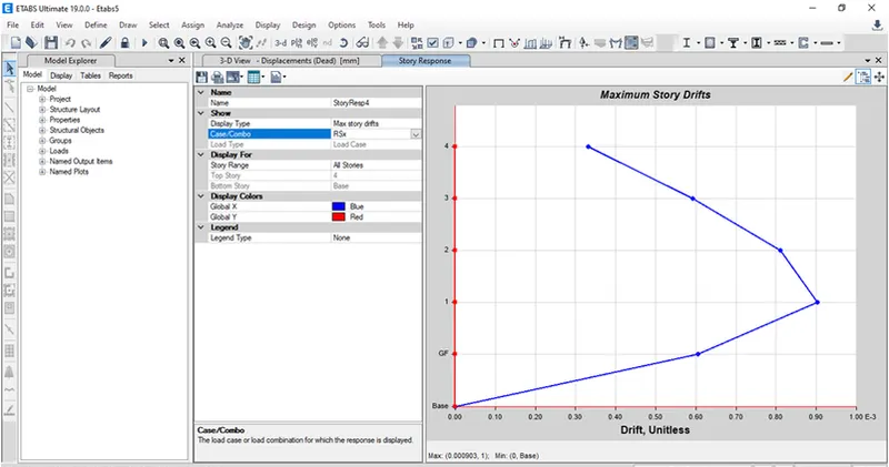
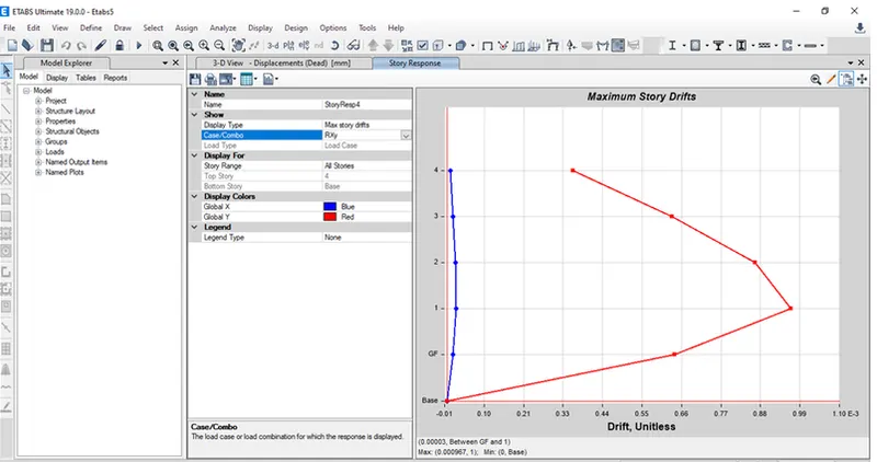
2) Storey response plot:
ii) For this go to Display-Story Response Plot- Maximum Storey drift
iii) Here storey response for maximum storey drift is less than 0.004 for both X and Y
21) Beam Design Check
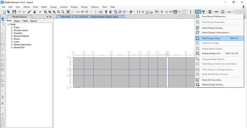
i) Click on beam design check
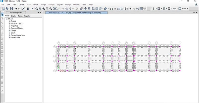
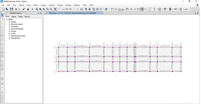
ii) Check for Beam Shear reinforcement
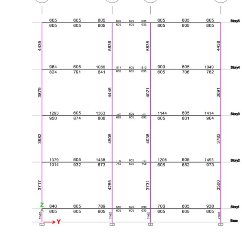
iii) Column Longitudinal Reinforcement
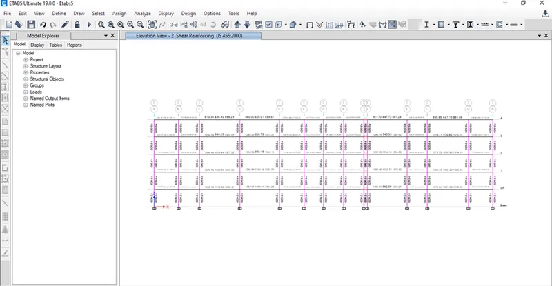
iv) Column Shear Reinforcement
Design of Foundation - Pile foundation
Step 1)
i) In order to export the ETABS model into SAFE click on file – Export – Story as SAFE V12.f2k file option
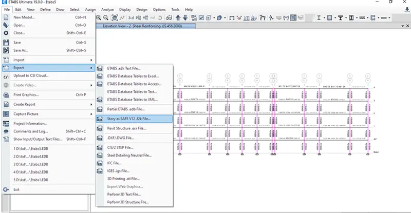
ii) Once you click on this option folowing diaog box will open
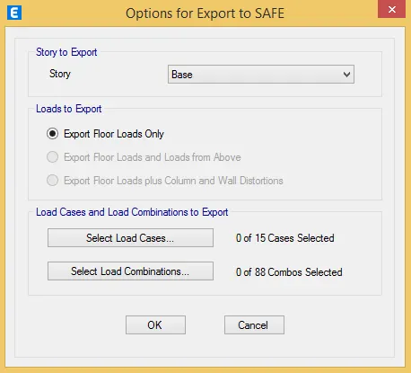
iii) Select Story as Base
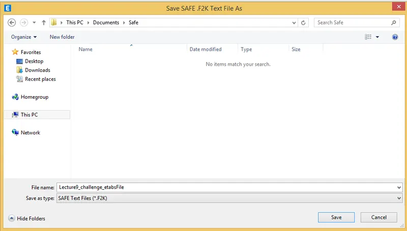
iv) Now Save the file to desired location
Step 2)
Given data:-
i) Column of size:- 550mm *550 mm
ii) pile has a load carrying capacity of 280kN
iii) Pile length-16 m and dia of pile -500 mm
iv) SBC-150kN/m^2
Step 3)
i) Number of piles=Total Axial load/pile capacity=(1.5DL+1.5LL)/280= numbers
ii) Piles in the springs are defined as spring so for that the spring constant
Step 4)
i) K=EA/L
E=5000(fck)^0.5=5000(25)^0.5=25000 N/mm^2
Area of pile =22/7*d^2=3.142*(500)^2/4=196375m^2
L-10000m
K=25000*0.7855/16=306835.9N/mm==419
Spacing of the piles as per clause number 6.6.2 of IS 2911
the spacing between the piles =2.5dia of the piles =2.5*500=1250mm
Step 5)
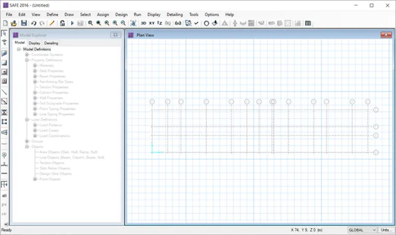
i) We can see that all the grids are exported to the safe.
Step 6)
i) Now we have to assign the Material proprties
ii) Define - Material Properties
i) Click on Add new materials
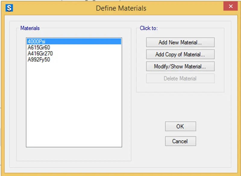
iii) Once you click Add new material add the following parameters
iv Material Type - Concrete
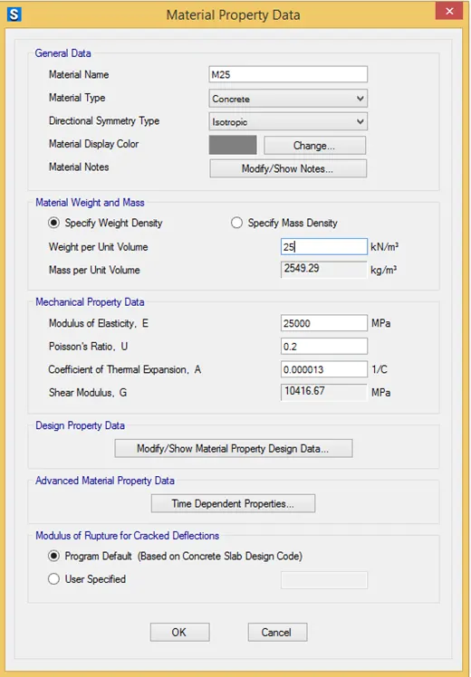
v) Grade - M25
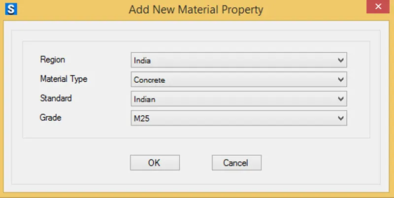
vi) Click on okay.
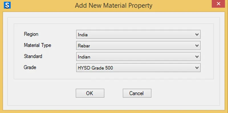
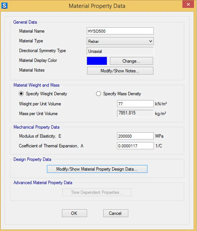
vii) Simialarly add the Rebar Properties
Step 6)
i) Now we have to define Slab properties
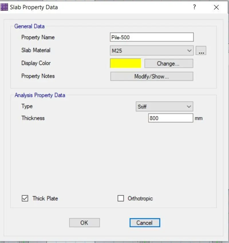
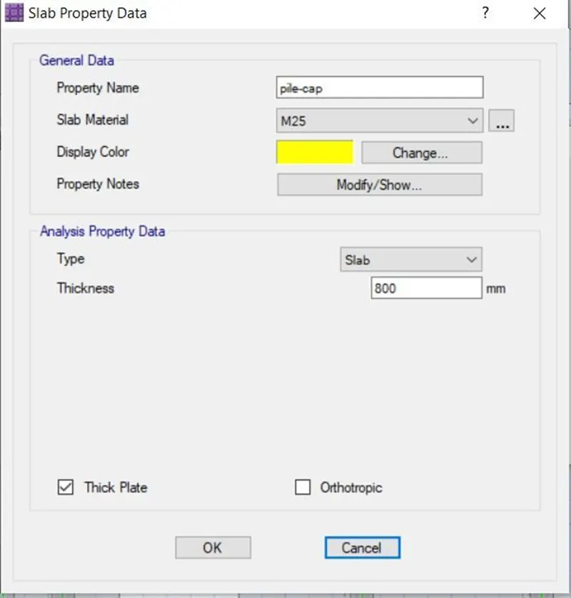
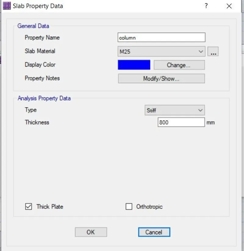
ii) In pile cap we have to define 3 slabs properties
iii) For Pile Foting
iv) For Column
v) For Pile cap
Step 7)
i) Once slab proerties are defined
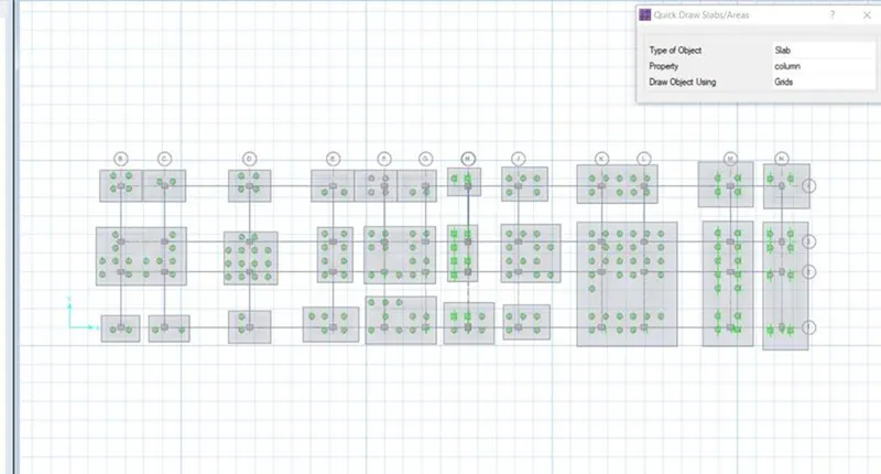
ii) Now we have to start the modeling
iii) Select Quick draw slab options
Step 10)
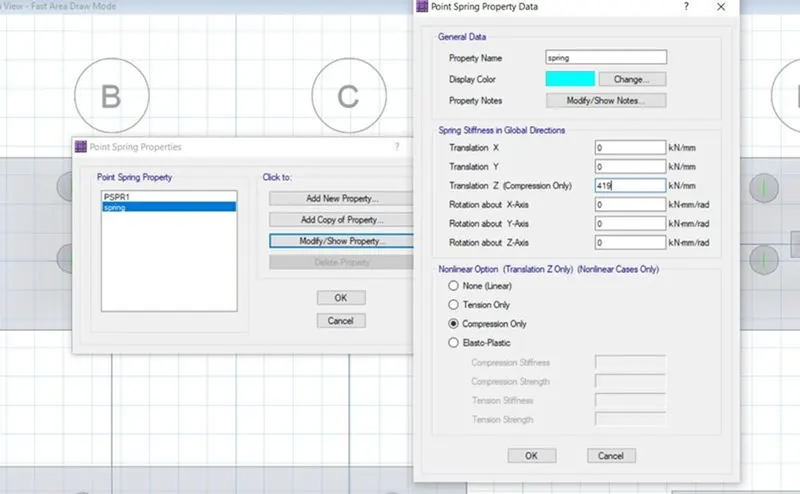
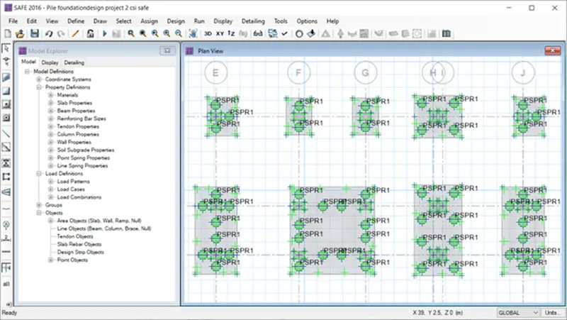
i) Now we have to add Springs to the pile because it behaves like a spring
ii) Click on Assign – Support Data – point springs
iii) Spring Constant from above calculation is taken as
iv) Add Spring Constant 419 kn/mm
v) Select - Compression Only
Step 11)
i) Check the model
ii) And Run the analysis
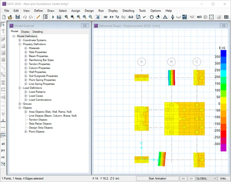
1) Check for Displacement -
We found that Displacement is less than allowable settlement
i.e 0.8 < 25mm
2) Check for Punching Shear -
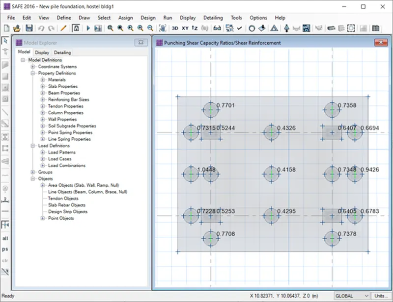
i) Click on Display - Punching Shear
ii) As we can see that Punching shear is less than 1
i.e 0.77 <1.....................................Safe
Step 12)
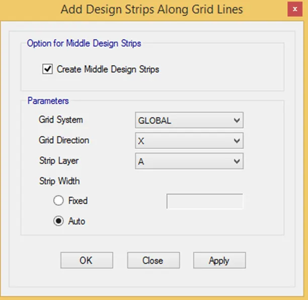
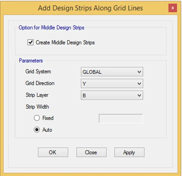
i) Now we have to add the Design srips
ii) Click on Edit - Add / Edit Design Strips
iii) Add the Strips in both X and Y direction
Step 13)
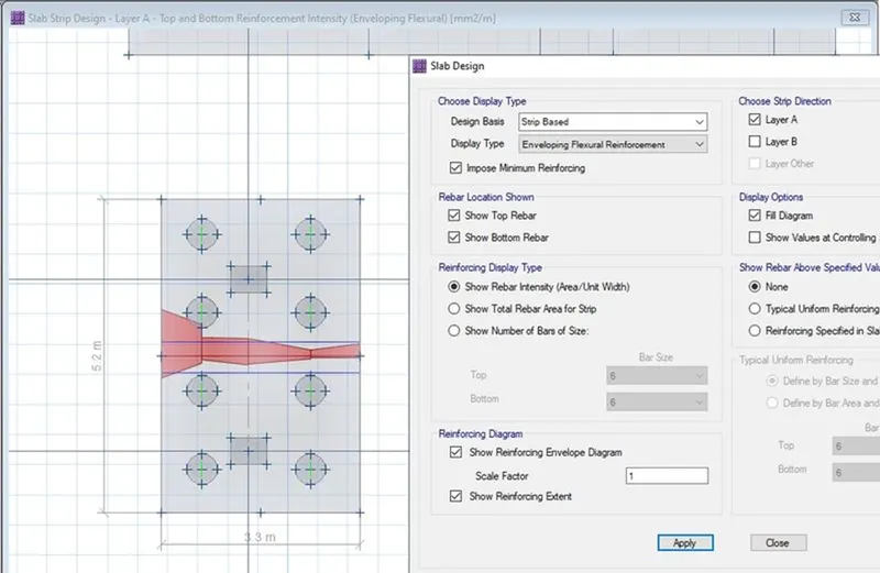
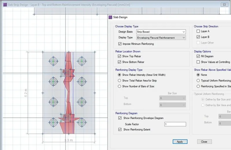
i) Run the model again
ii) Click on Display - Show slab Design
Similarly in B direction
Results -
i) G+3 hostel was designed and analysed in ETABS
ii) Foundations was designed and analysed in SAFE
All the check are done as per IS 13920-2016