Project 2_Design & Analysis of a Hostel building at Guwahati, Assam
In this project, participants will get to experience the entire design process from modelling, analysis, design and preparation of construction drawings. The architectural drawings of a G+3 RCC building is provided. The following information on the building is to be used:
- Location – Guwahati, Assam
- Function – Hostel block in an academic institute
The walls will be made of AAC blocks. Other loadings are to be calculated as per the architectural drawings.
The buildings rests on type 3 soil. Piles of length 10 meters and 500 mm diameter with load carrying capacity of 280 KN is to be used.
The ground floor level will be at a height of 2 meters above existing site level to avoid flood water enter the building.
M25 grade of concrete with Fe500 for longitudinal reinforcement and Fe 415 for shear reinforcement is to be used.
The following design IS codes will be required for reference:
- IS 875 part 1
- IS 875 part 2
- IS 13920
- IS 1893
- IS 2911 part 2
- IS 456
- SP 34
Students will have to produce the following:
- ETABS model for the two blocks on either side of the expansion gap
- Foundation details illustrating the pile & pile cap reinforcement
- Tie beam details connecting the pile caps
- Column reinforcement
- Framing plan for typical floor
- Beam reinforcements for ground floor
AIM:
We have to model a G+3-Story building using ETABS and foundation design using SAFE for seismic load modelling, analysis and design of building of structural rebar drawing of a hostel building located in earthquake prone Area, Zone V.
OBJECTIVES:
- To calculate and assume necessary data from the given architectural and site information.
- To model analysis and design the frame structure using key tabs software.
- To model analysis and design the foundation using safe software.
- To produce in structural typical floor plant and typical rebar drawings.
PROCEDURE:
Data required for ETABS analysis.
- Pinned support, base + 5 story (plinth to roof) + 1 Mumty.
- Column 450 mm X 650 mm Beam 400 MM X 500 mm, Slab 150 mm thick. No shear wall is necessary.
- Floor live load. 2 KN/m2.
- Terrace live load 1 KN/m2.
- Floors finish + Ceiling finish. 1 KN/m2.
- Partition wall load 3.5 KN/m2.
- Balcony wall load 1 KN/m.
- Guwahati seismic Zone V.
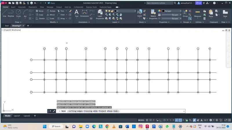
- To make a Column layout as a reference in AutoCAD.
We have assume and make a column layout in AutoCAD. So it will be easy in ETABS modelling.
2. Proceeding in the ETABS
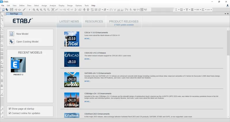
- Open the ETABS software.
- Click on the New Model in it.

3. Now Creating a New Model in ETABS
- After Clicking in new Model
- A Model Initialization Dialogue box will appear.
- Then Click on Unit BUilt in Settings.
- Use the Settings as shown in the Image below.
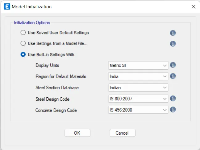
4. Creating Grids by Using AutoCAD Drawing we have made as a refrence.
- After this a new dialogue box will appear.
- Now Click on Custom Storey data.
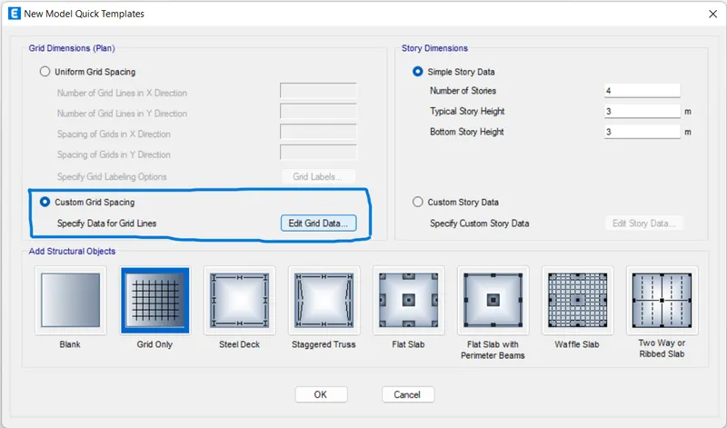
- A new dialogue box will Open< Here enter the X spacing and Y spacing.
- Now nter the Details using Refrence drawings. in X axis and in Y axis.
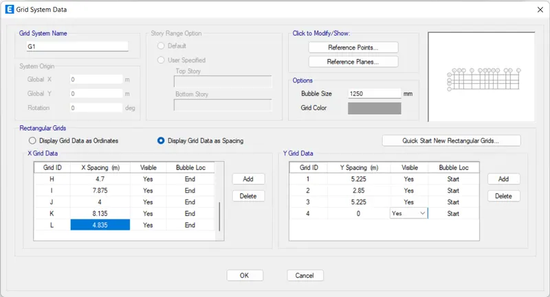
5. Enter the Storey Data.
- Now Click on Custom Storey Data.
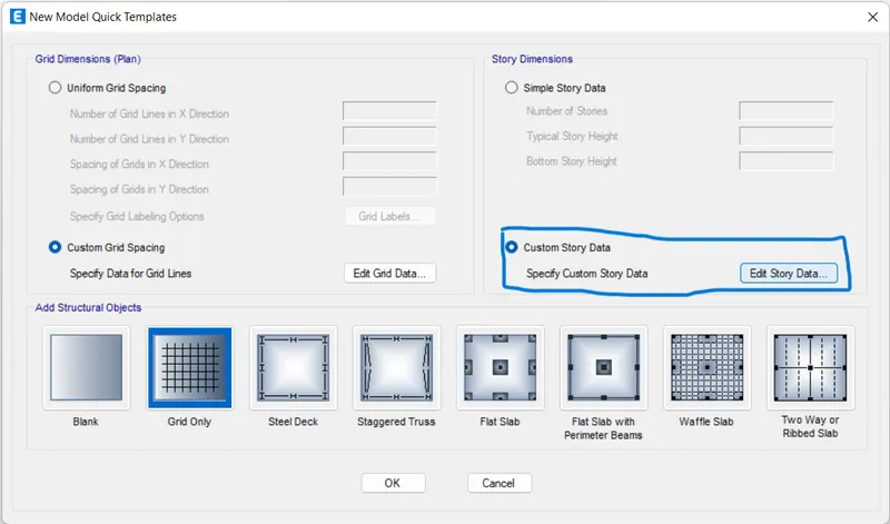
- A dialogue box will appear
- Here ente rthe Storey Details uding Refrence drawings as given.
- Now Click on OK.
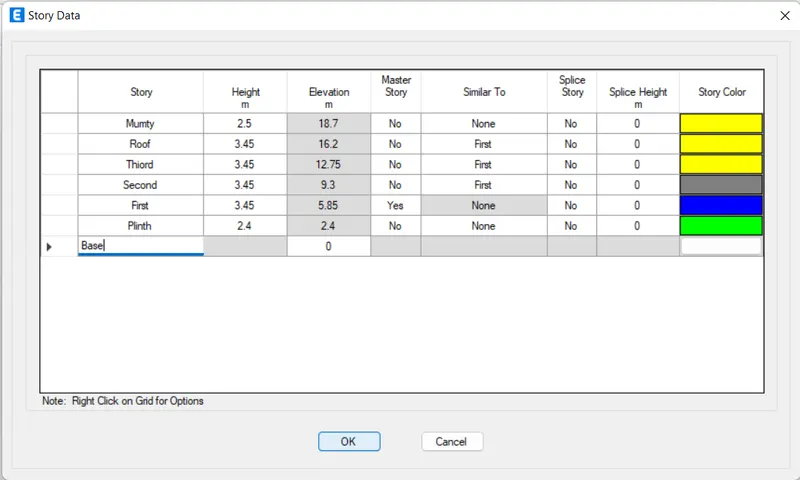
- This Will appear.
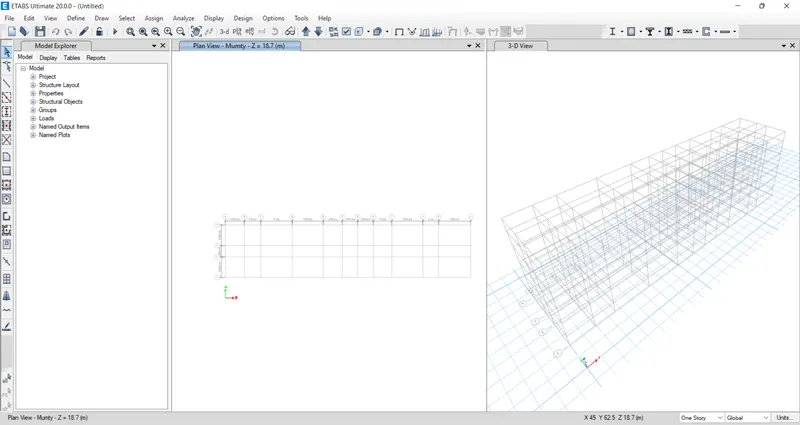
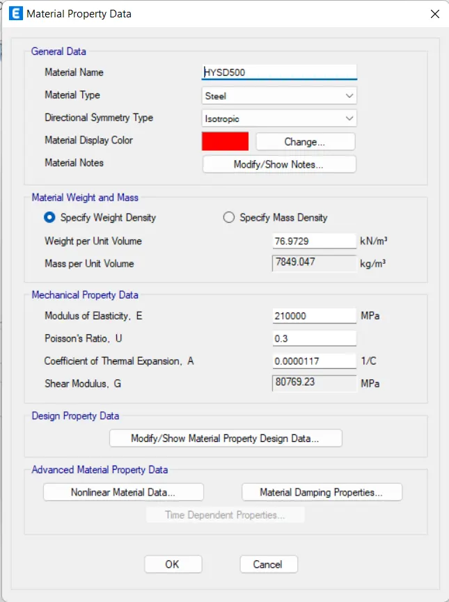
6. Now we have to Define the Materials.
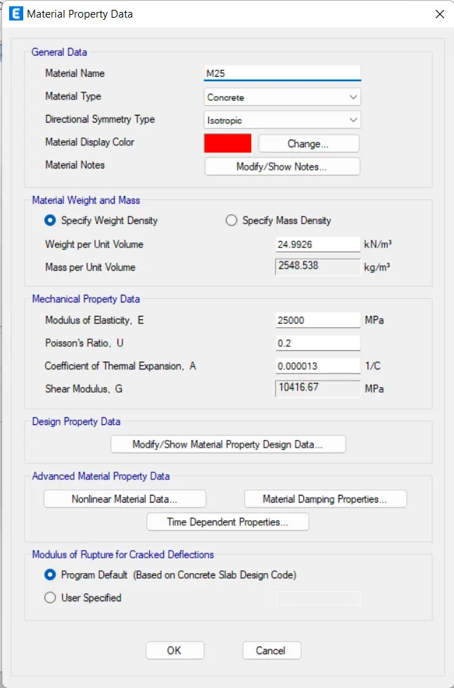
- Click on Define<Materials.
- A Add New Material dialog box will open, select Material Type as Concrete.
- Add M25 concrete.
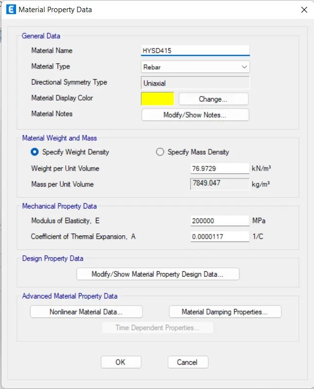
- Now Again Select Material Type as Rebar.
- Add HYSD 415 rebar property.
- Now Again Select Material Type as Rebar.
- Add HYSD 500 rebar property.
7. Now Adding Beam property.
- Click on Define
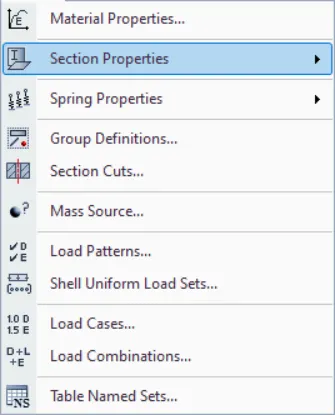
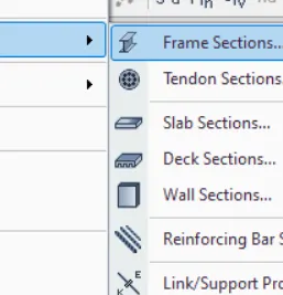
- Click on Add new Property
- Click on Rectangular Section for Beam.
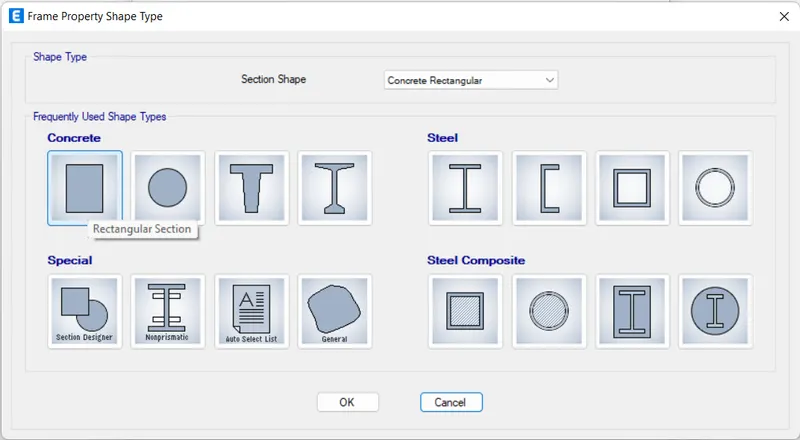
- Change the Peoperty name aS B400x500 and B300X500 and Material as M25.
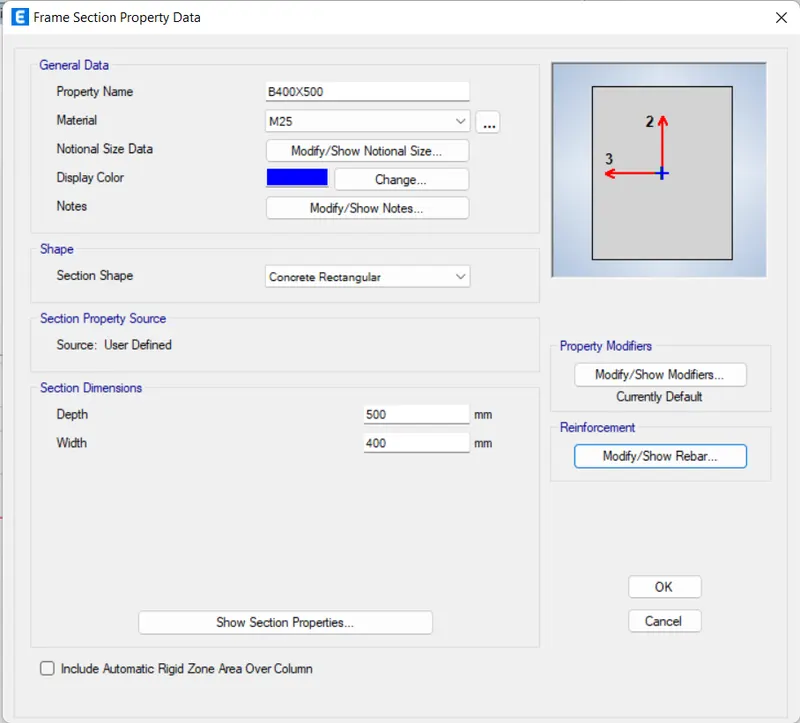

- Also Change Design Type and Rebar Material
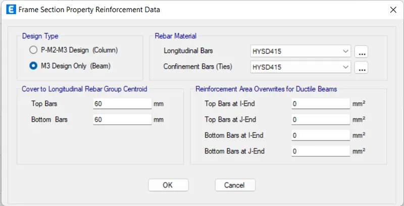
- Click OK.
8. Now Adding Column Property.
- Click on Add new Property.
- Click on Rectangular Section for Beam.
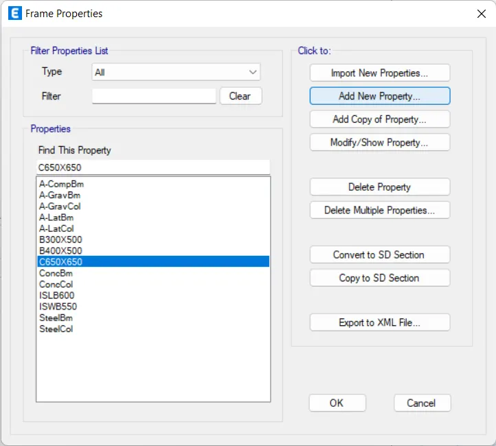
- Change the Peoperty name aS C650x650 and Material as M25.
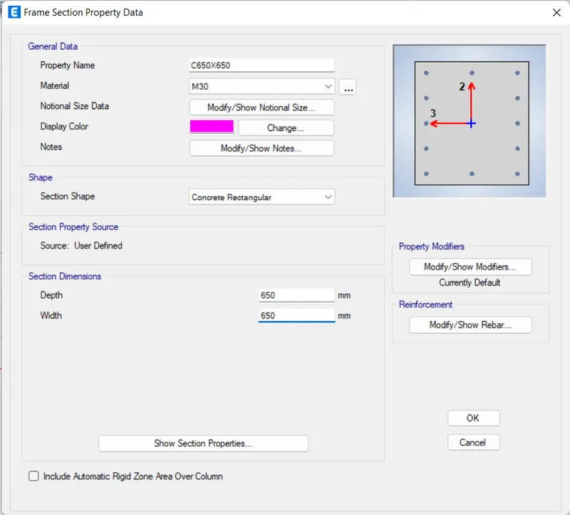
- Also Change Design Type and Rebar Material.
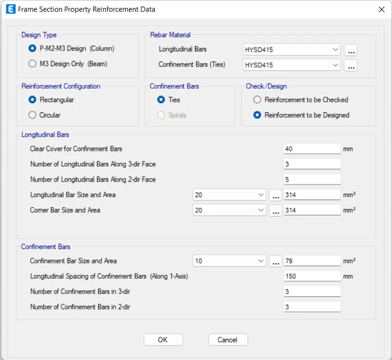
- Click OK.
- Yoy see Properties are added.
9. Now we have to add Slab Property.
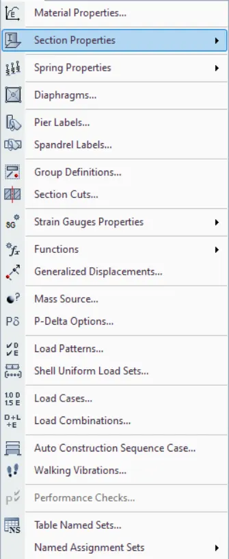
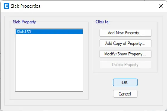
- Go to Define< Slab Section< Section Property
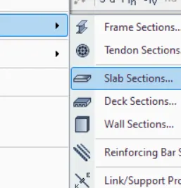
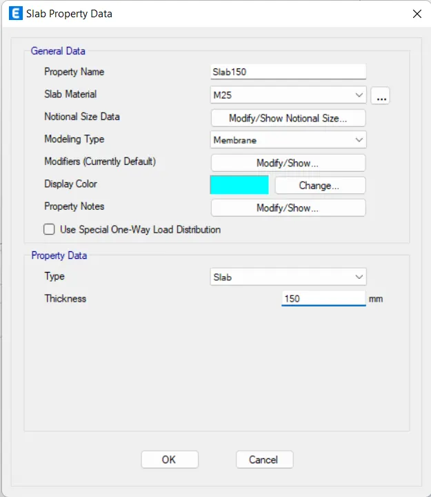
- Click on Add New Property for Slab
- Now Change the Property name as S150 and Material as M25.
10. Adding the Load Patterns.
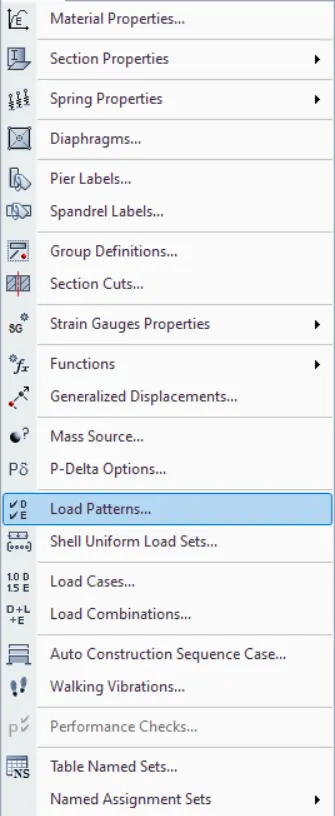
- Go to Define< Load Patterns.
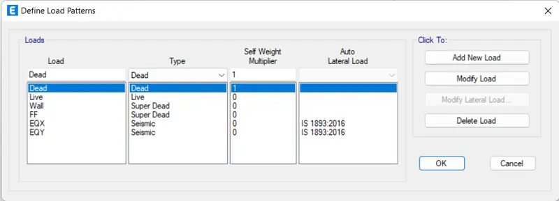
- Add Wall Load as Super Dead type
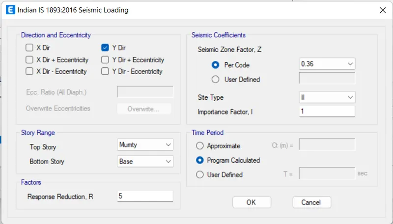
- Simalry add EQX & EQY Load as Seismic type and select IS-1893:2016
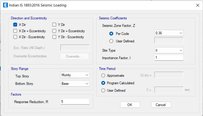
- Modify the lateral load and uncheck the other direction except X for EQX and Y for EQY
- Change the Zone as per the code i.e. 0.36.
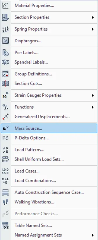
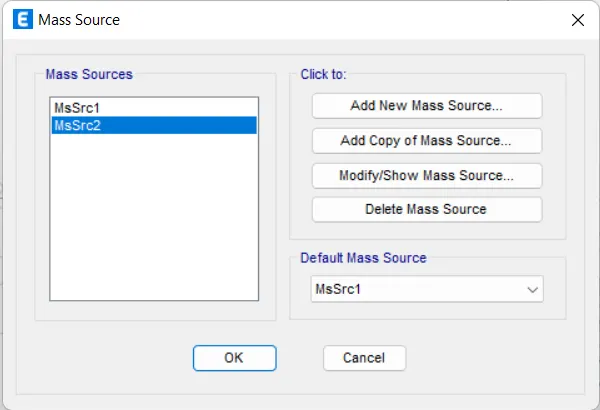
11. Now we have to Define Mass Source.
- Click on Define
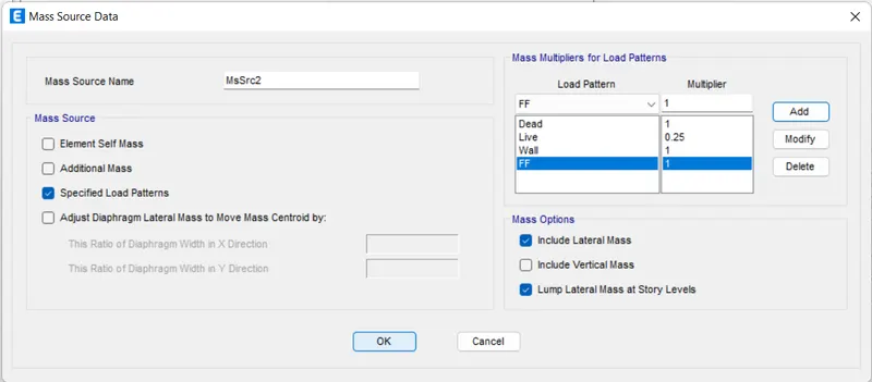
- Now Check mark only Specified Load Patterns.
- Now specify load patterns as shown.
12. Now Specify Response Spectrum.
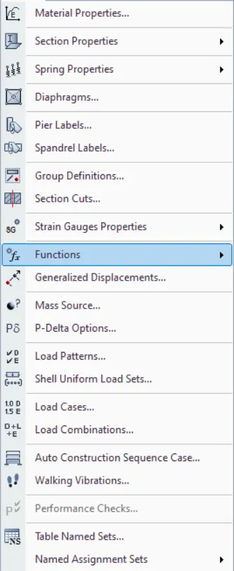
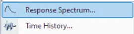
- Click on Define<Functions
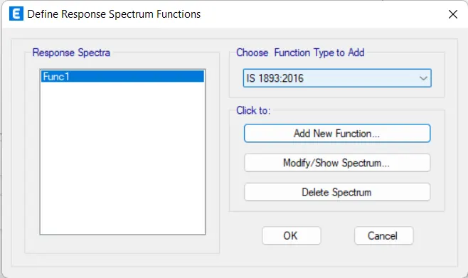
- As Given in the question this buildying Is Come under Zone 5
- So as per IS 1893 the importance factor is 1.5.

13. Check the Load Cases
- Go to Define< Load cases.
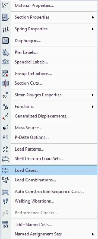
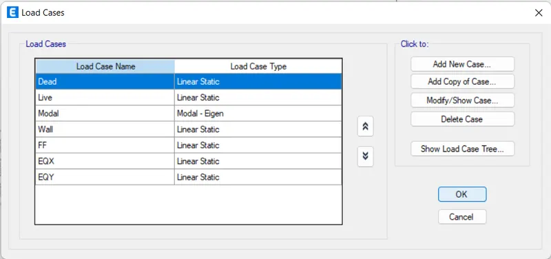
- Click on Ok.
14. Add Load Combination.
- Click on DEfine< Load Combination.
- Now Click on Add Default.
- Now Check on Folloeing Boxes as given below.
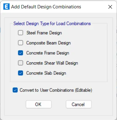
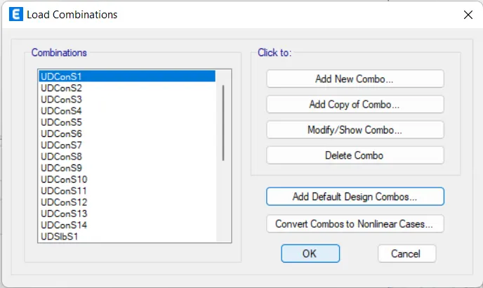
- Click on OK.
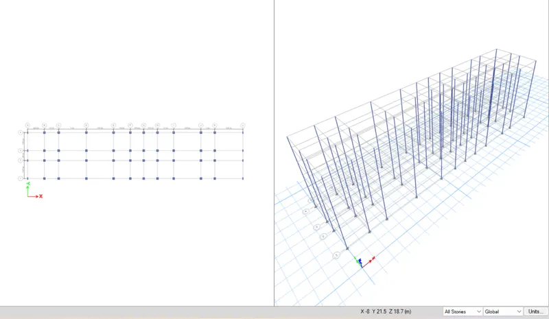
15. Draw Column
- Select Quick Draw Columns
- Select column size from the property browser.
- Change to All stories.
- Now draw the columns.
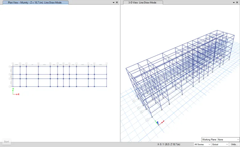
14. Draw Beams.
- Select Quick Draw Beams.
- Select Beam size from the property browser.
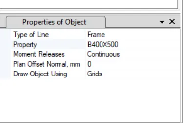
- Change to All stories.
- Now draw the Beams.
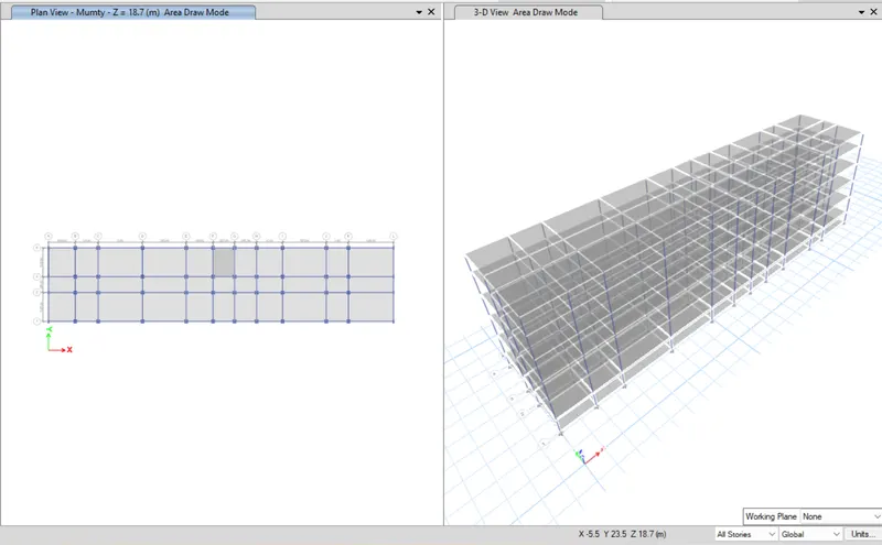
16. Draw Slabs.
- Select Quick Draw Slabs.
- Select Slab size from the property browser.
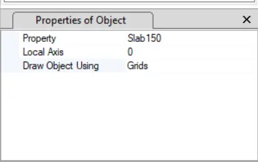
- Change to All stories.
- Now draw the Slabs.
17. Now its Time to Assign Loads on it.
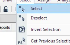
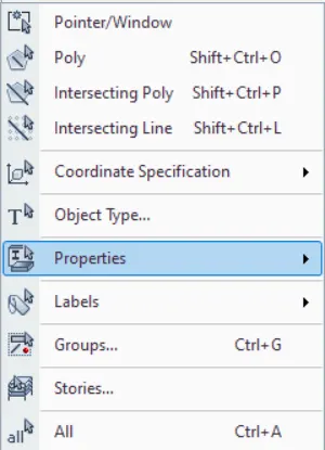
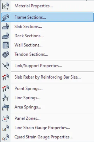
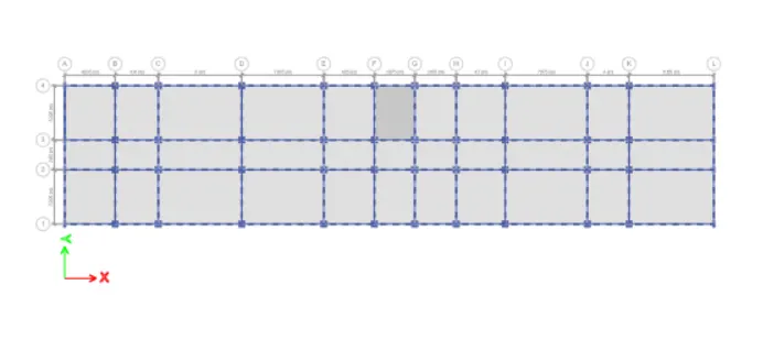
- Select all beams by Click on select<Properties
- Then Select the beam size from the dialogue box.
- The beam is selected
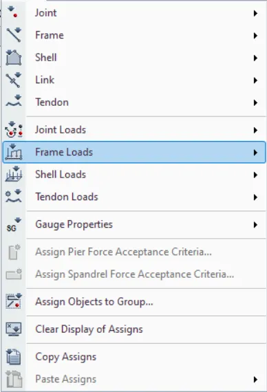
- Now Assign Frame Load as Distributed
 .5
.5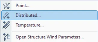
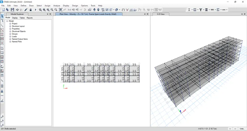
- Enter the Uniform Load value as 3.5kN/m.
- You see the load is assigned
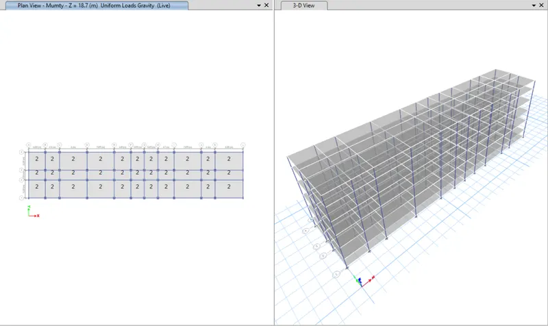
- Now Select all the Slabs
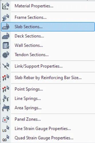
- Now Assign Shell Load as Uniform
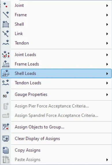
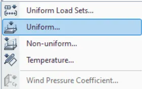
- Enter the Uniform Load value as 1kN/m.
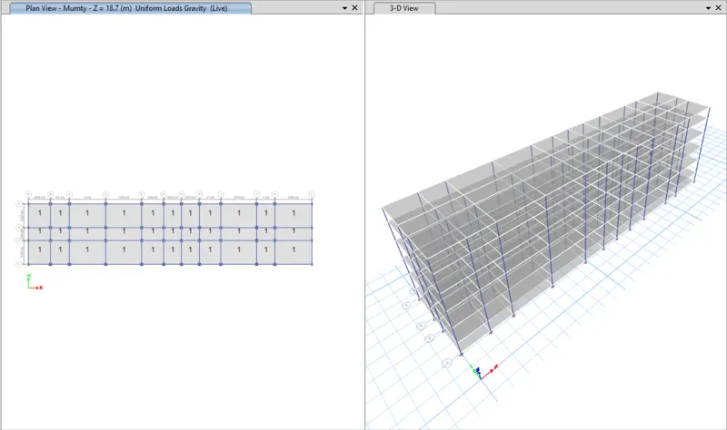
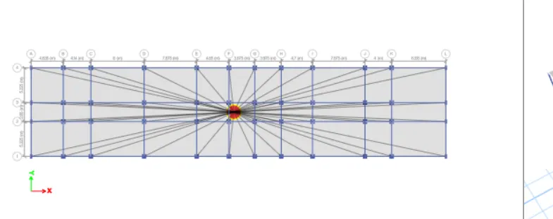
18. Adding Diaphgrams.
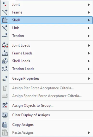
- Select All Slabs
- Click on Shell<Diaphgrams.
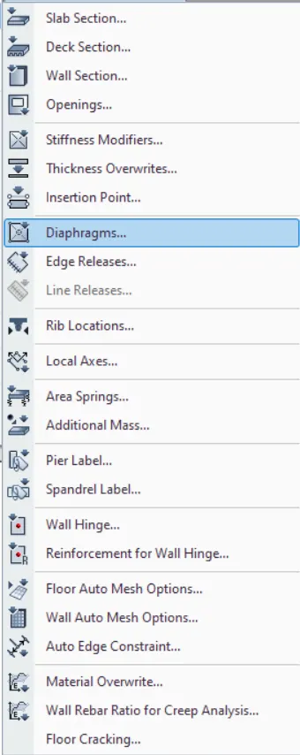
- Now select Slab150
- Click Ok.
19. Run the Analysis.
Click on Run the Analysis.
The analysis will Start.
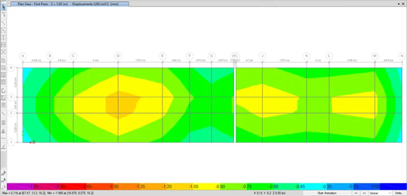
20. Verifying and Performing Steel Design Check.
- Check concrete design for RC beam longitudinal reinforcement
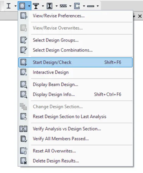
- Shear reinforcement
- Verify the all member are passed
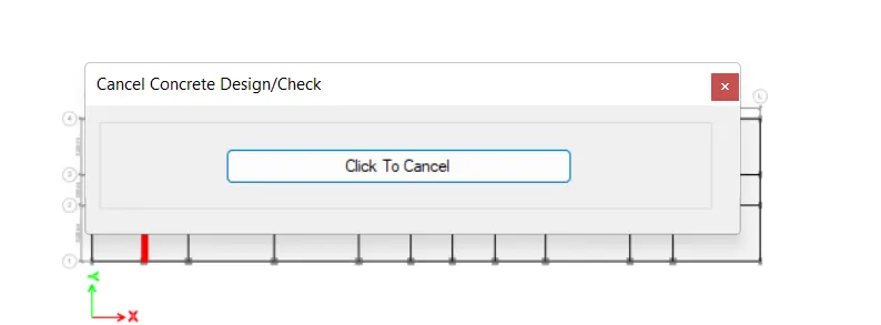
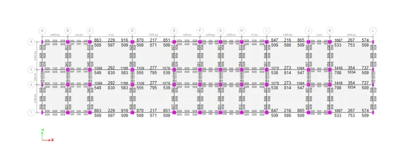
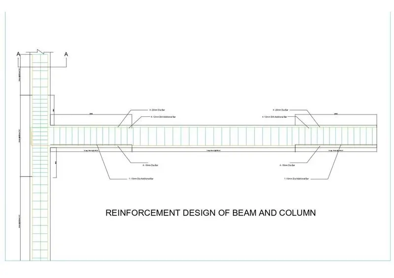
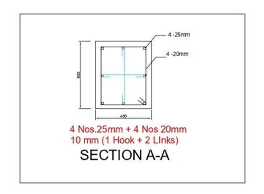
21. Rienforcement Beam and Column Detail.
22. Now export the model As SAFE.
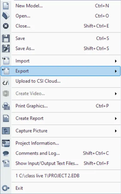
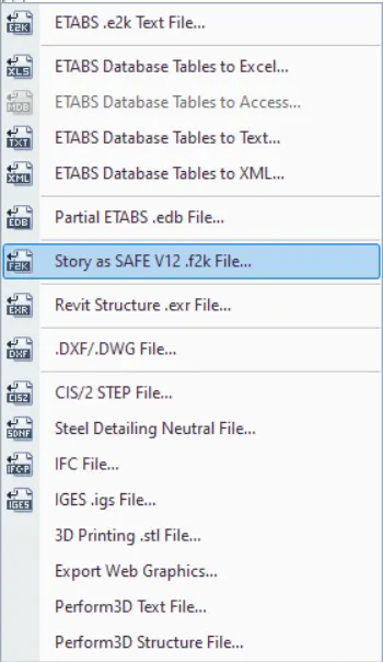
- Select File and then click on Export as safe .f2k file
- Now select the story
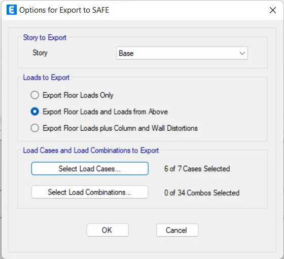
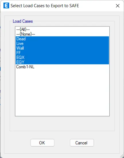
- then select the load cases and load combination.
23. Import the Model in SAFE.
- Open thye Safe Software.

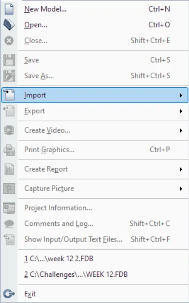
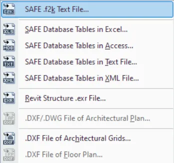
- Now click on File > Import> Safe.f2k file
24. Data Required for the Safe Analysis and Design-
Total load = Sum of all loads
Load= 192.3157+790.3119+96.1578+183.4126+207.2068+230.7760
= 1700.1808 kN
Dead load breakup =1700.1808 /2 = 850.904kN
live load breakup =1700.1808/2 = 850.904kN
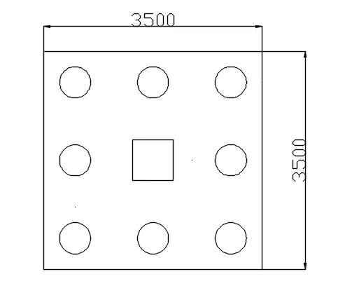
no of pile = axial load/ capacity of single pile = 1700.1808/280 = 6.07 = 8 pile required
so that area of pile = 3.14x250^2 = 196250m^2
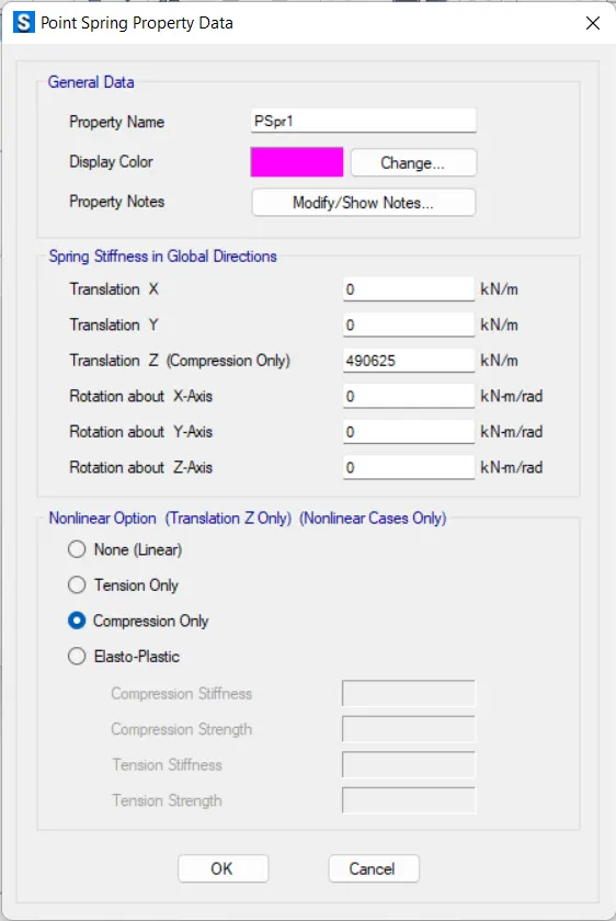
point spring of pile = (AXE)/L=(196250X2500)/10000 = 490625 kN/m
min. spacing b/w pile = 2.5D = 2.5 x 500 = 1250mm
edge distance = D=500mm
Extract data-
Column size = 650 x 650mm
Diameter of pile= 500mm
Axial load (Unfactored load) = 1700.1808 kN
Loading capacity of each pile is = 280kN
25. Define materials
- Click on Define>Materials.
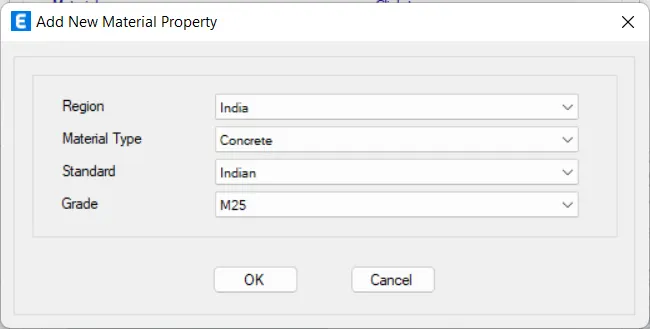
- Click on Add new material and add as concrete grade of M25

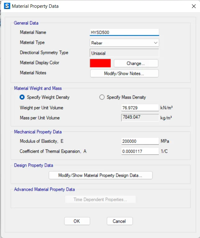
- Click on Add new material and add as Rebar HYSD500.
26. Define slab properties.
- Click on Define> Section properties> slab properties
- Click on add New
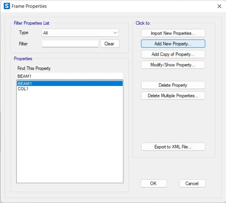
- Add section property as a COLUMN STIFF
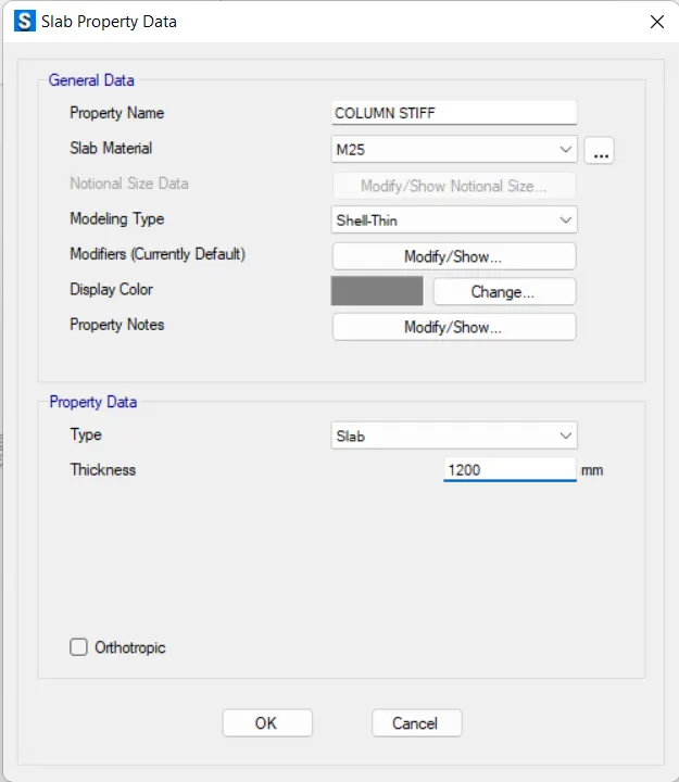
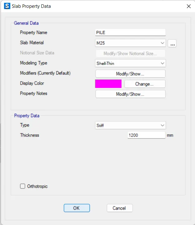
- Add section property as a PILE
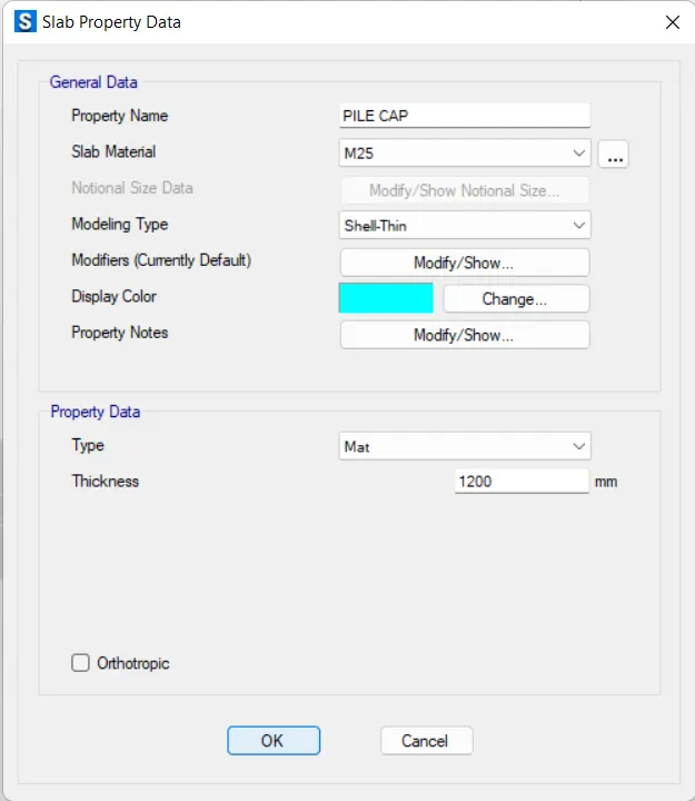
- Add section property as a PILE CAP.
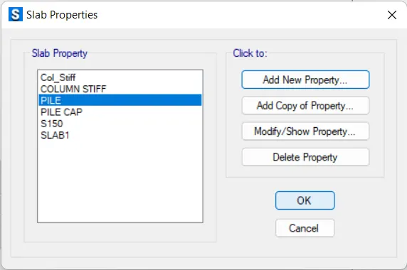
- You see all propewrties are added
27. Now Define Spring Properties.
- Click on Define> Spring propereties> Point sprimgs
- Click on add new
- Add New spring
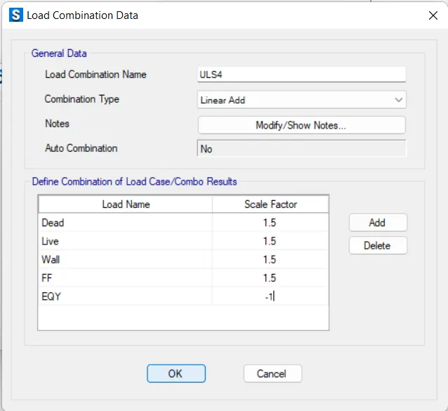
28.Now Add Load Combination data.
- Click on Define > Load combination.
- Click on Add new
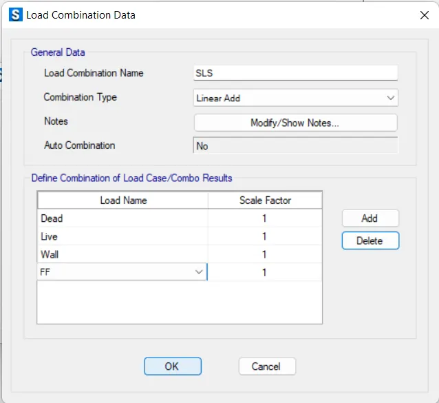
- Add serviceabilty limit state load SLS
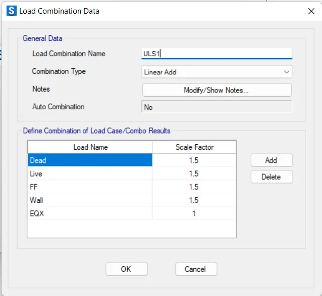
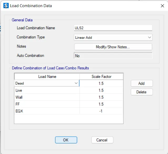
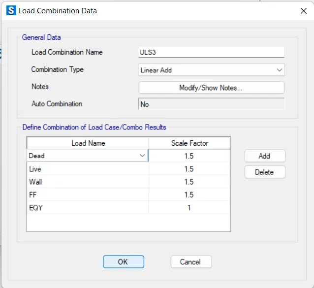
- Now add Ultimate limit state factored loads
29. Draw the pile cap.
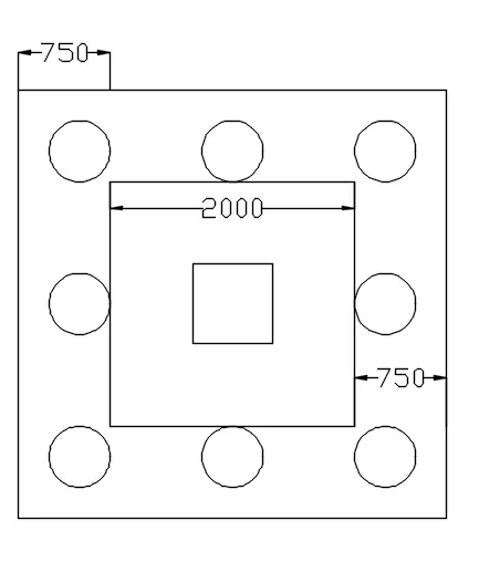
- I draw the pile cap In AutoCAD as a refrence.
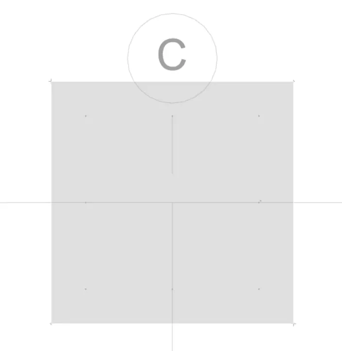
- Now In SAFE First Draw the Refrence Points.
- After draw the Joint Objects.
- Now Draw the Slab
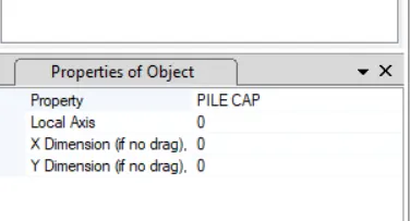
- Now Draw the Piles
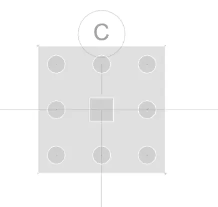
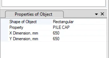
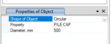
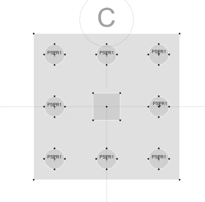
30. Assign the Springs on Pile.
- Select All the Points of Pile.
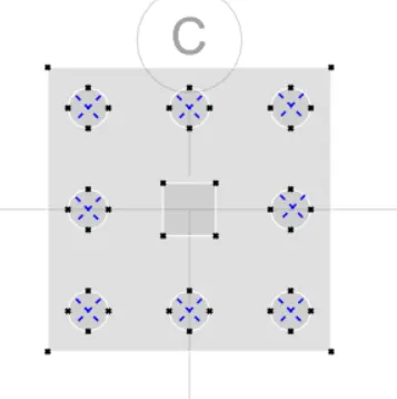
- Asssign the Spring load on selected piles
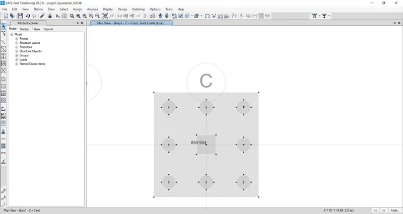
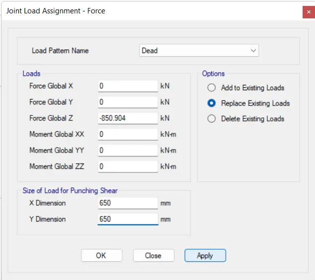
31. Assign Joint Load on Column
- Click on Assign> Joint load > Force.
- Now Add the dead and live load as calculated
- Click on Apply.
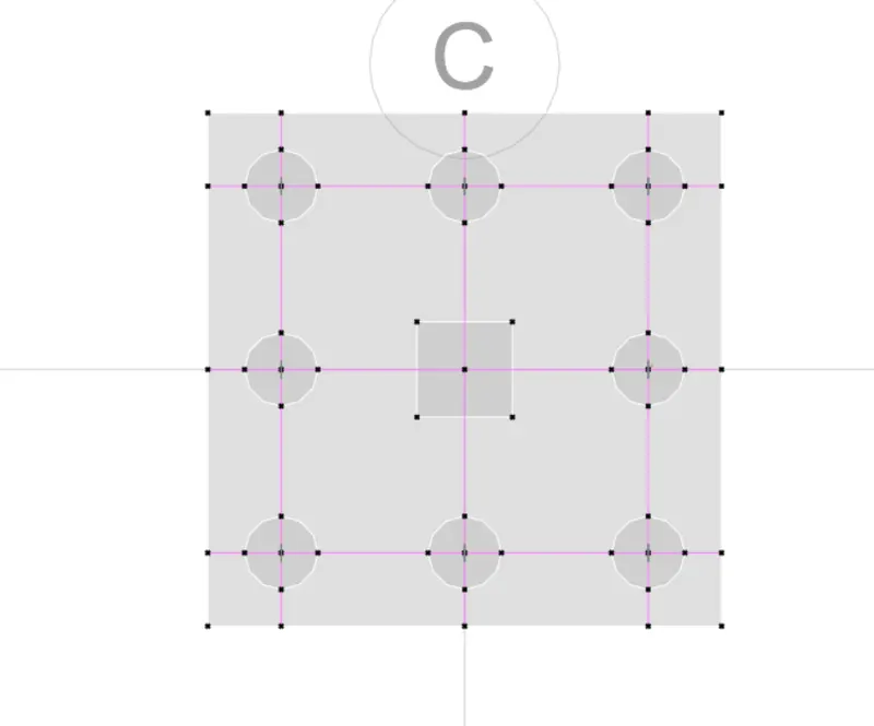
32. Draw the Design Strips.
- First draw the Refrence Points.
- Now Draw the design Strip in X direction as layer A.
- Now Draw the design Strip in Y direction as layer B.
33. Run the Analysis.
- Press F5.
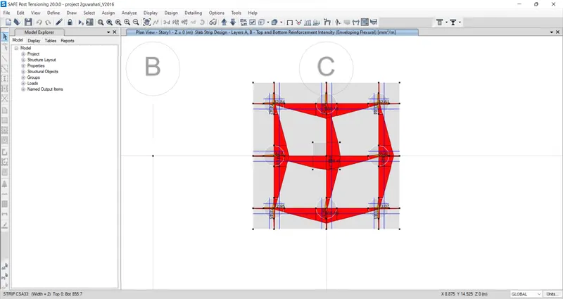
- The Result as shown.
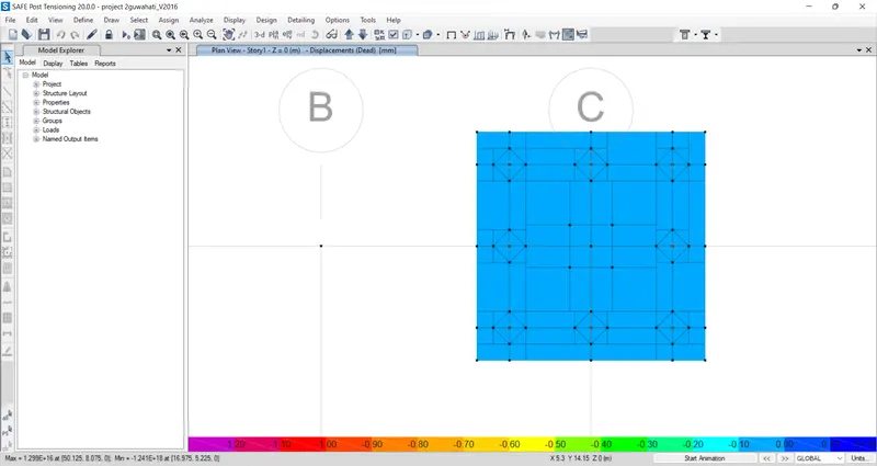
- Punching Shear
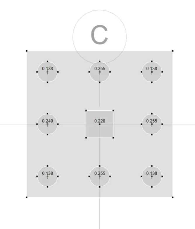
- The Point Spring loads on piles.
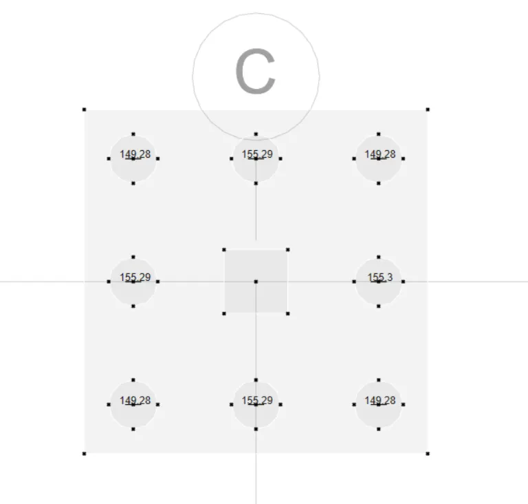
- Reinforcement Detail.