Project 2_Design & Analysis of a Hostel building at Guwahati, Assam
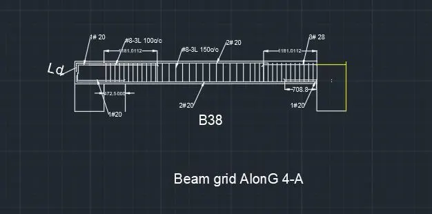
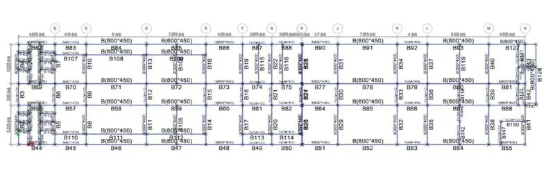
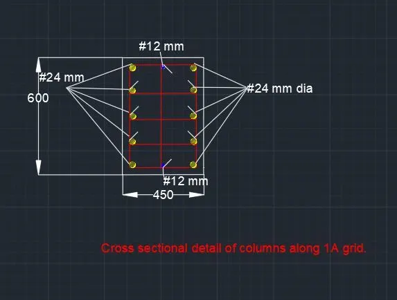
AIM:- The structural model has to be created and analyzed using the specified building in ETABS 2018 in line with IS 1893 and IS 13920. To create the ground floor frame plan and beam detailing, as well as the pile cap and pile reinforcement details, tie beam linking the pile caps, and column reinforcement sketches.
provided data:
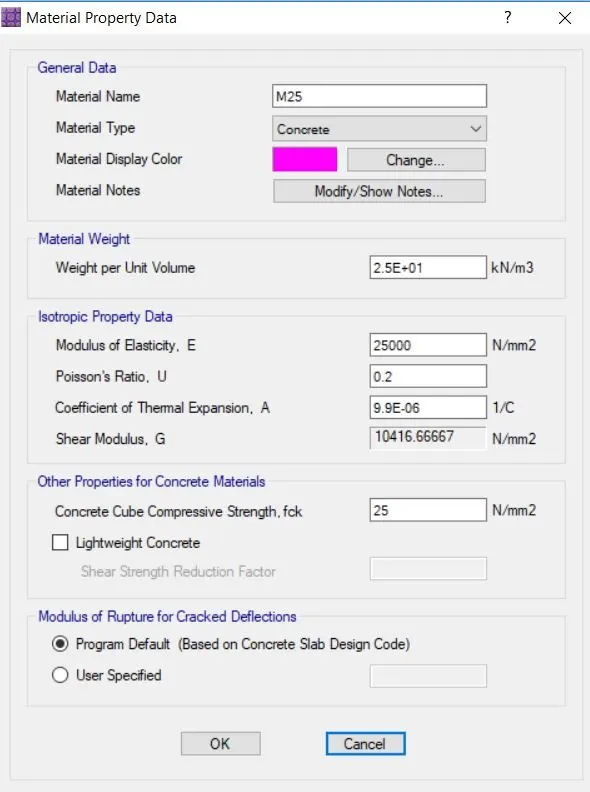
AAC blocks are used to build the wall. Pile strength: 280 kN, M25 steel, Fe 500, and soil type 3.
Procedure:
- Open the Etabs program, then select File > New Model from the menu.
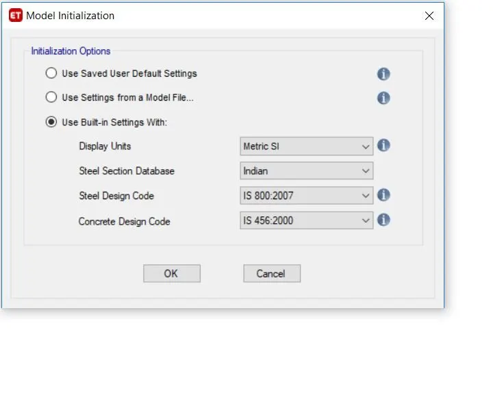
- A window for initializing the model will emerge.
- Select the Indian codes by clicking the utilize built-in setting, then click "OK."
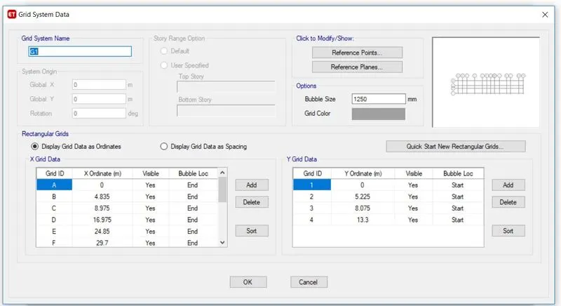
- Select the custom grid data, then select OK.
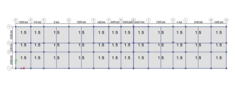
- As soon as the values specified in the plans are added, our model will be complete.
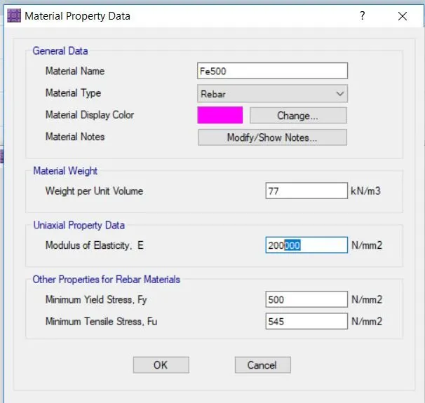
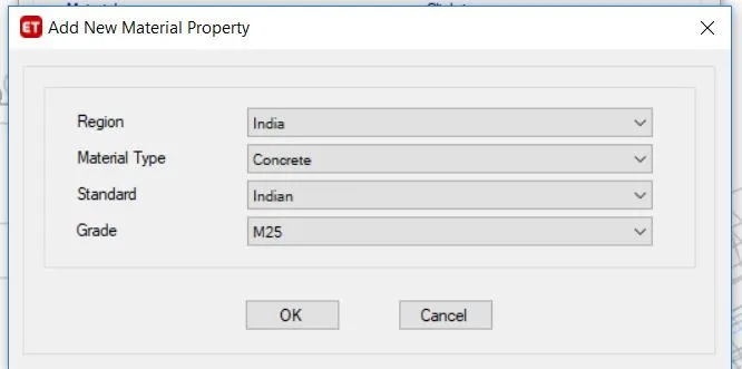
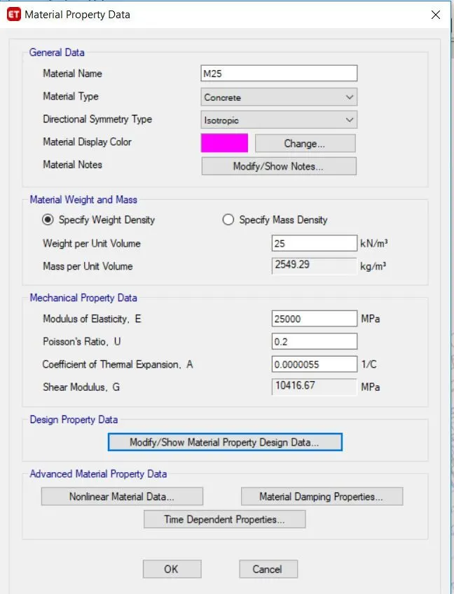
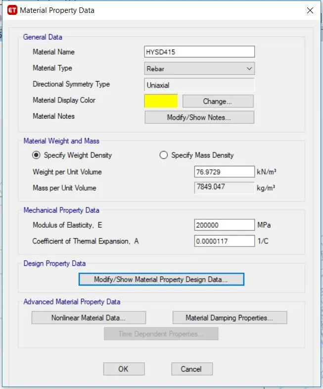
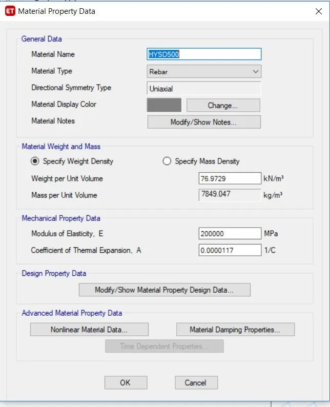
- The next stage is to specify the substance. Go to define, choose material characteristics, and then specify the concrete and rebar materials.
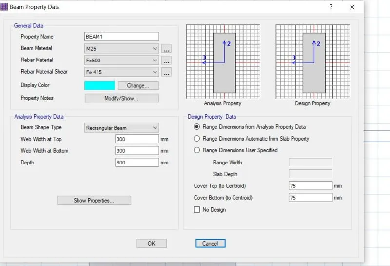
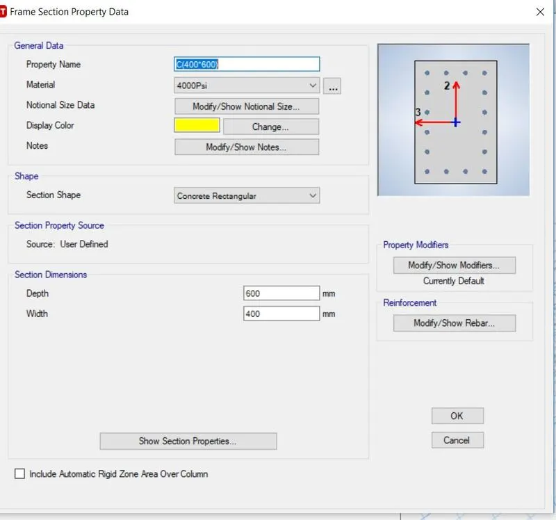
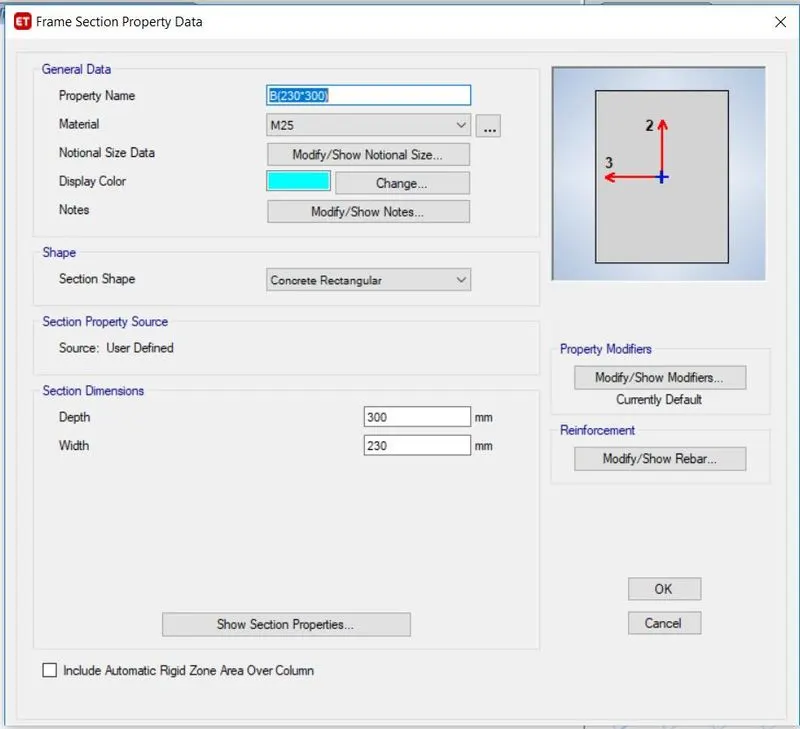
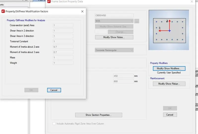
- Properties need to be defined in the subsequent step section. Add the beam and column specification by going to define and selecting section characteristics.
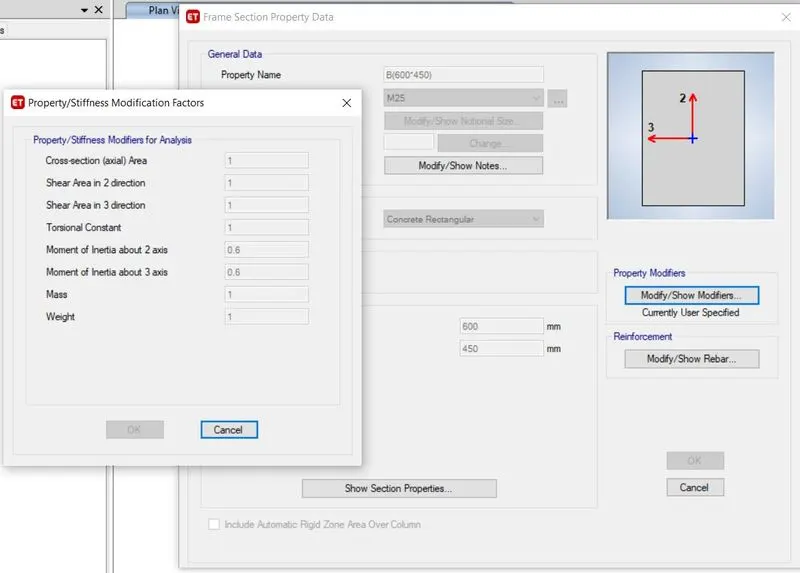
- For each beam, a 450 mm x 600 mm beam size is offered.
- For the beams at the periphery, 450 mm x 600 mm beams are installed to strengthen the building's torsional resistance.
- Reduce the moment of inertia of the columns and beams by 0.4% and 0.35 percent, respectively.
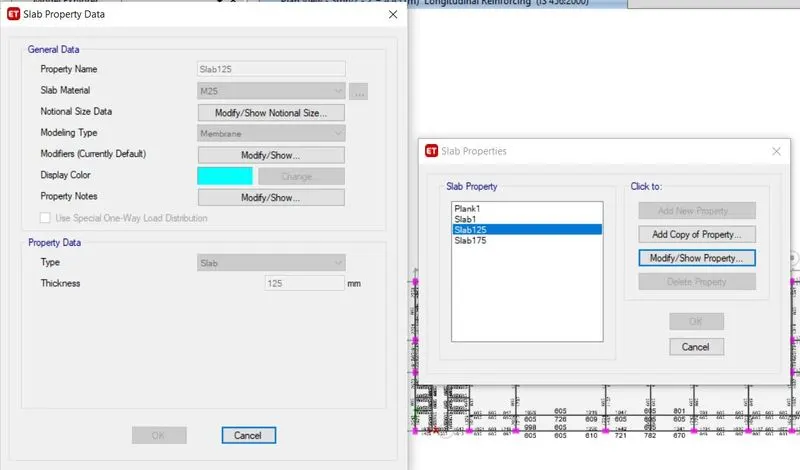
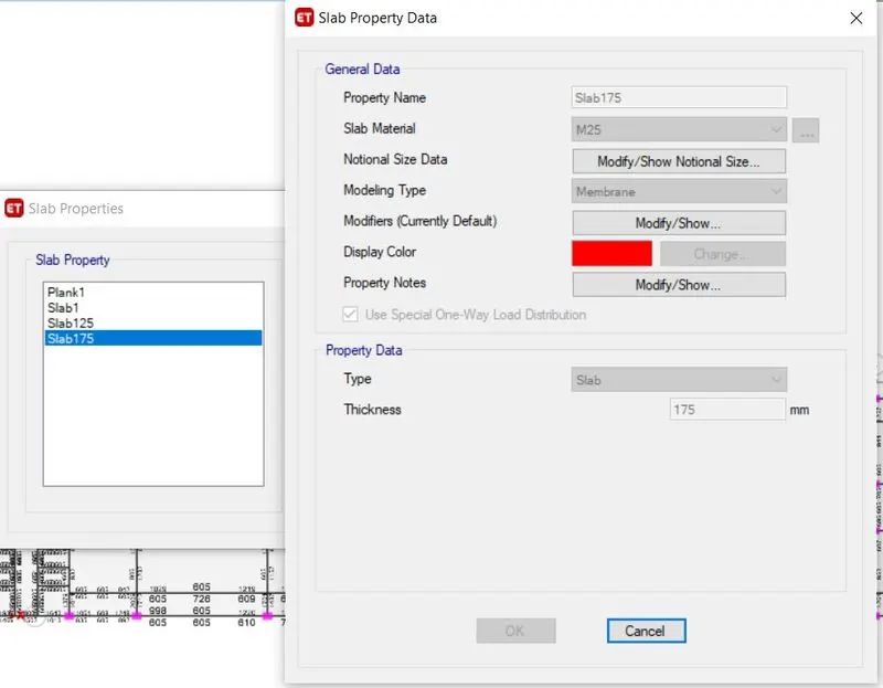
- Define the slab properties by entering the define and slab sections in the next step. Slab attribute should be included as it should be One way when specifying the slab for the Staircase.
- Give a description of the stairway slab and its 175 mm thickness ( varies from 175-225mm)
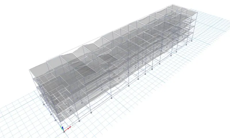
- Using the beam command, draw every beam.
- Use the column command to draw every column.
- The slabs command is used to draw slabs in the subsequent phase.
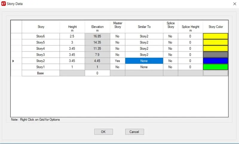
- According to Indian norms, the wall's length should be 5-2% in each direction.
- It is believed that the shear wall is 250 mm thick.
- Go ahead and specify the loads now.
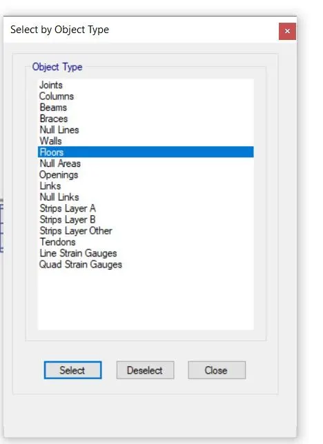
- The loads are then added after choosing the beams and flooring.
- AAC load of 3.5 kN/m due to the utilization of aac blocks.
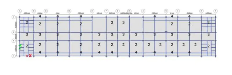
- The live load values for residential structures are taken from IS 1875 Part 2. according to IS 875 part 2 table 1
|
Living Rooms,Bedrooms and dormitories |
2 kN/m^2 |
|
Kitchen and Laundries |
3 kN/m^2 |
|
Billiards and public lounges |
3 kN/m^2 |
|
Store rooms |
5 kN/m^2 |
|
Dining rooms,cafeterias and restaurant |
4 kN/m^2 |
|
Office rooms |
2.5 kN/m^2 |
|
Bath and toilets |
2 kN/m^2 |
|
Corridors, passages, staircase |
3 kN/m^2 |
|
Balconies |
4 kN/m^2 |
- Part 2 reduction factor should be applied to the imposed loads in accordance with clause number 875.
- It is necessary to lower the live load at the roof floor, hence 2 kN/m is used.
- On each floor, 2 kN/m of floor finish is applied.
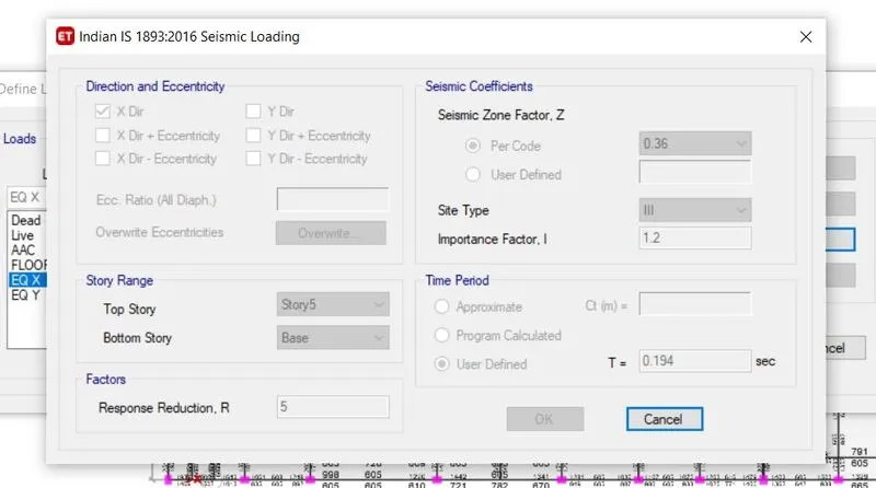
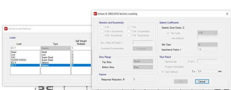
- According to IS 1893 Table No. 8, seismic loads should be defined with an importance factor of 1.2 considering the building.
- Time is determined in accordance with IS 1893 clause 7.6.2, T=0.09h/sqrt.
- Tx=(0.09*16.85)/(67.7)^0.5=0.184 Seconds. Or Ty=0.09*16.85/(13.3)^0.5=0.415 sec
- Identify the load combinations now.
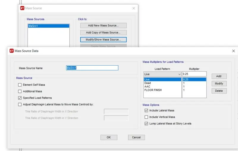
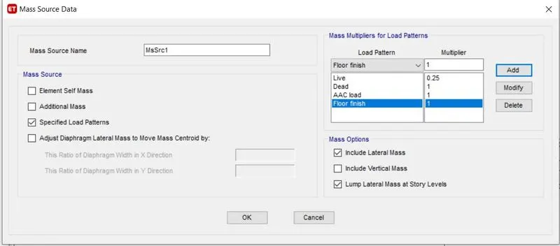
- The next step is to define the mass source. To do this, go to define, click on mass source, add a new one, select specified load data, select include lateral mass and lump lateral mass at story levels from the mass options, and then add multipliers of 0.25 for LL and 1 for all dead and
- super dead loads to the load pattern.
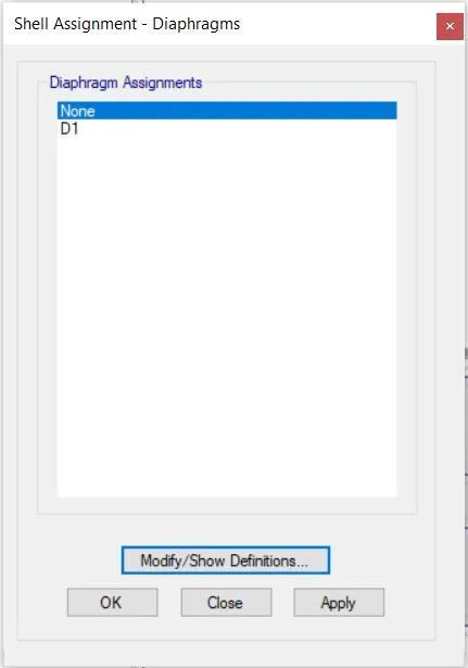
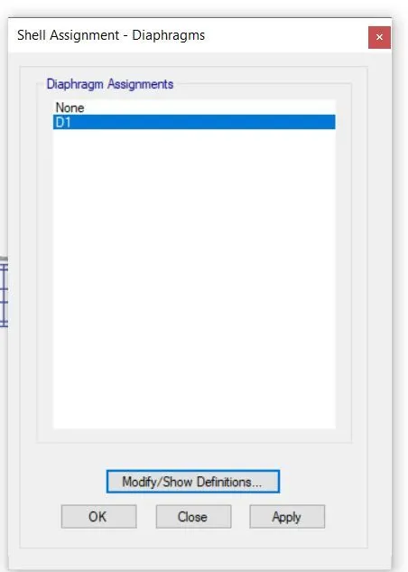
- Additionally, choose every floor, then use D1's diaphragm.
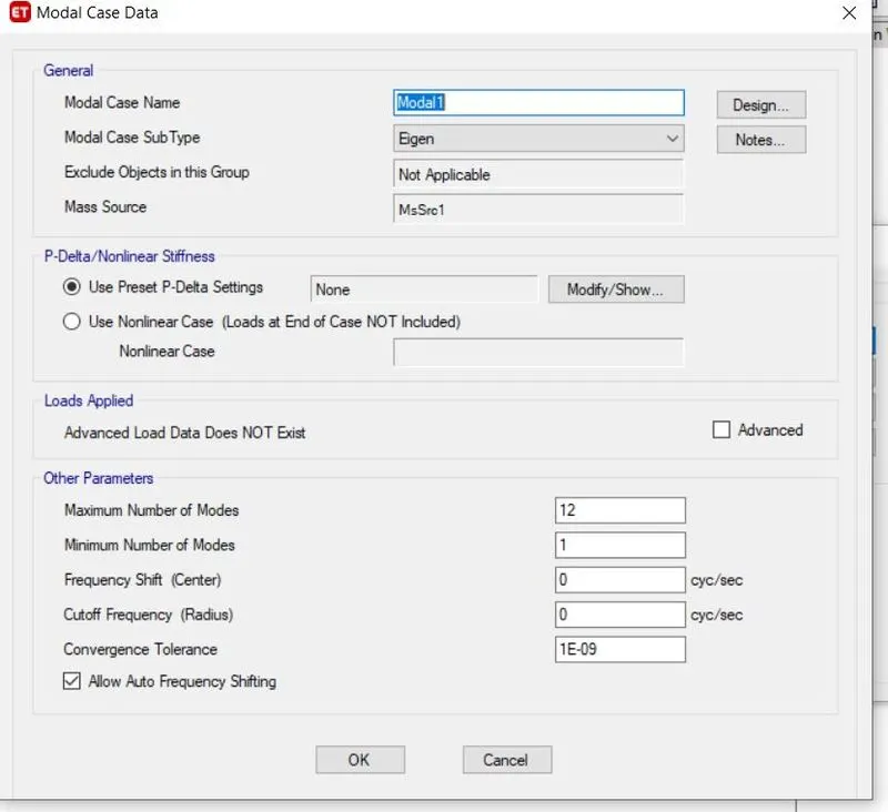
- The next step is to define the modal cases. To do this, go to define, click on modal cases, add new model cases, choose Eigen, and enter the necessary number of modes.
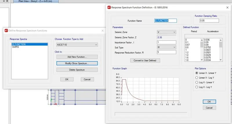
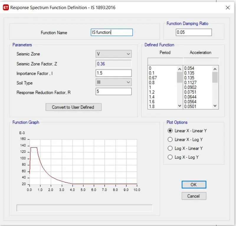
- Name the function as the IS function; the Response Spectrum IS function IS 1893-2016 tab will open; verify all the values for the soil type, important factor, and seismic zone factor; then click on the linear x and linear y buttons to accept.
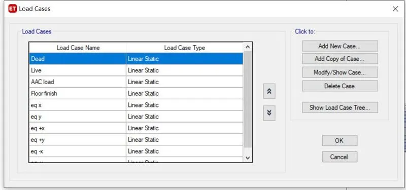
- now navigate to create Load cases, choose to Add a new case, and then add RSX and Rsy.
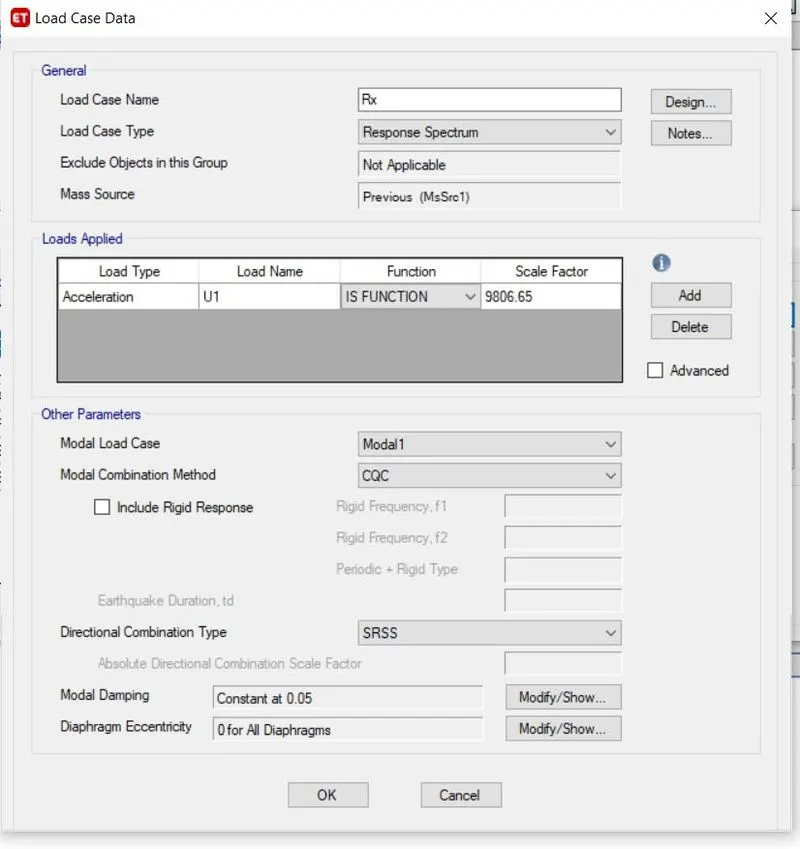
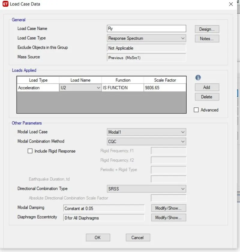
- choosing the response spectrum, adding it, choosing the IS function, U1 for Rx, U2 for Rsy, and IS function
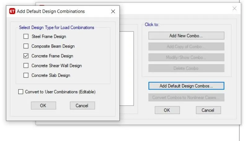
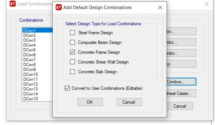
- Going to define, select load combinations, default design combo, create frame design, convert to design combo, and click OK.
- Check the model once more, make any necessary corrections, and then run it.
Results and discussion
- Go to display, click on the show tables and structural data buttons, and then click OK.
- Select the Analysis findings structure output and then click "OK" after selecting "Show Tables".
- If the RX RY values are fewer than the Eqx Eqy values, unlock the model, pick the base reaction, verify the eqx eqy values, Rx and Ry value, and then select the load combinations again and define that again.
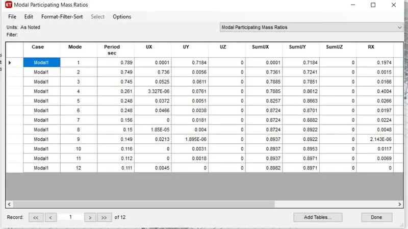
- Check the values for U1 U2 U3 and the total of these values for UX Uy UZ for the first 3 modes. It should be larger than 65%.
-
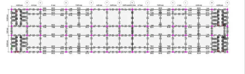
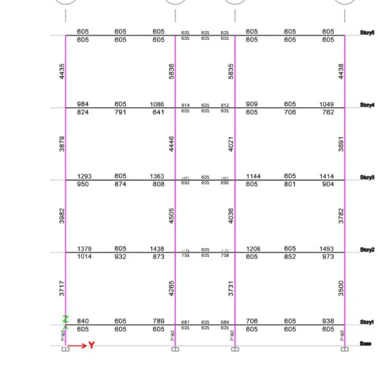
Select the start design or check under the concrete frame design. and record the quantity of reinforcement information.
-
decide on the modal participation rates We have that at mode 7, and we have above 90%, so everything is OK.
-
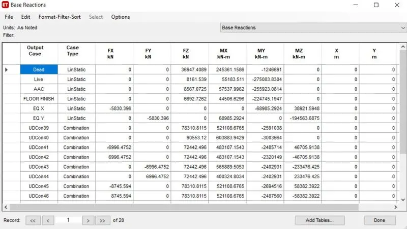
Next, choose the basic reactions and make sure that the values for Eqx and Eqy are the same, as well as that those for Rsx and Rsy are at least equal to those for Eqx and Eqy, respectively. If not, just divide the rsx values by the equivalent values to get the values that must be multiplied in the load cases rsx tab.
- check for the share of shear walls go to base level and click on reaction Ex and ey values will be available take these values and divide them by the Total base shear which should be greater than 90%. If now add the shear walls in the appropriate directions
 .
.
Importing the Safe 2016 software
- Select safe v12.fk under export in the file menu.
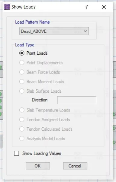
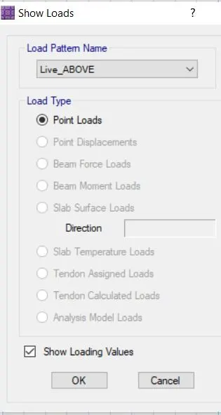
- After selecting the tale as the base and selecting the loads and loads from the top, selecting the combination, and clicking "OK," a tab will open.
- Go to SAFE 2016 and pick the file to import. Save the file as an FDB.
- When you go to the television and click on the show, the values for the deceased and the loving will be displayed.
-
Given data:-
Column of size:- 450mm *600 mm & 600mm*450m m
pile has a load-carrying capacity of 280kN
Pile length-16 m and dia of pile -500 mm
SBC-150kN/m^2
Solution:
- Number of piles=Total Axial load/pile capacity=(1.5DL+1.5LL)/280= numbers
- Piles in the springs are defined as spring so for that the spring constant
K=EA/L
E=5000(fck)^0.5=5000(25)^0.5=25000 N/mm^2
Area of pile =22/7*d^2=3.142*(500)^2/4=196375m^2
L-10000m
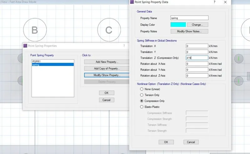
K=25000*0.7855/16=306835.9N/mm==419.
- Spacing of the piles as per clause number 6.6.2 of IS 2911 the spacing between the piles =2.5dia of the piles =2.5*500=1250mm
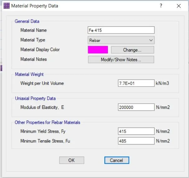
- Now, in the following stage, we must define the material properties for concrete and reinforcement qualities Fe500 & Fe415 in order to proceed.
- Choose the values.
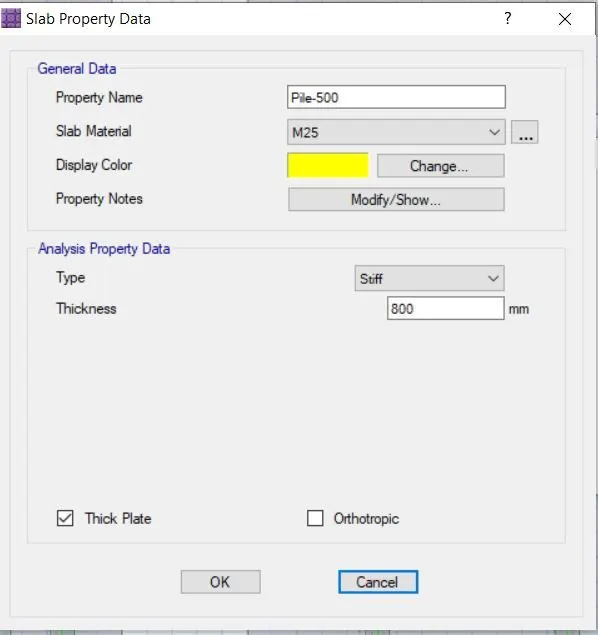
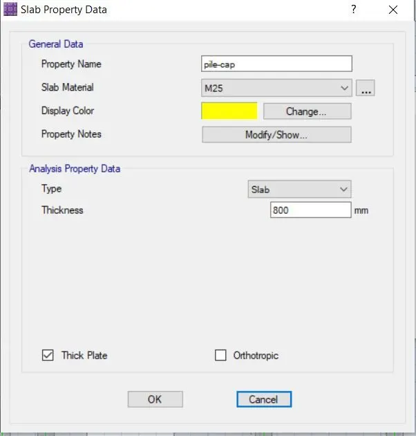
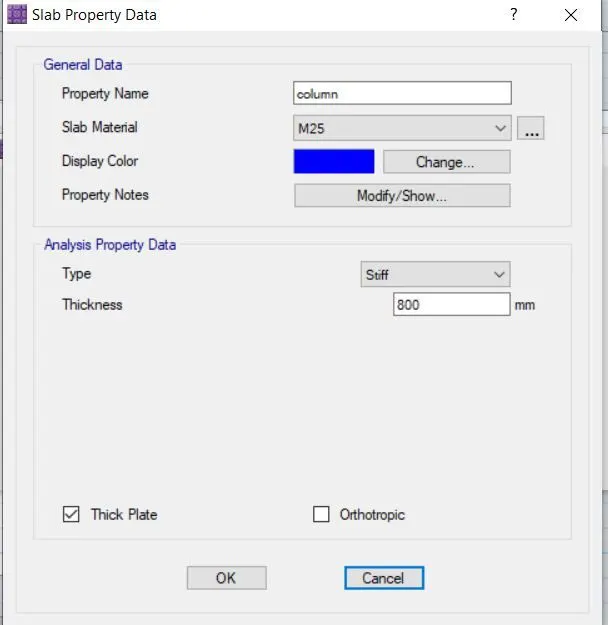
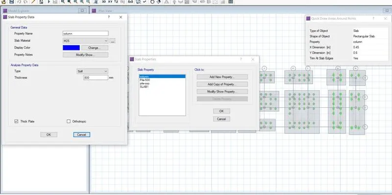
- Specify the pile caps, the pile diameter, and the column under defined section attributes.
- Add a new, defined pile cap using 500 as a Mat and a Stiff Column.
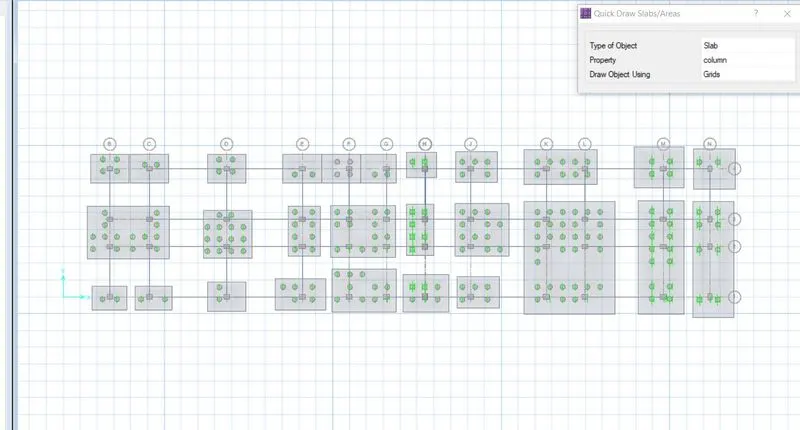
- When you select "Quick Draw Around the Plots," a new window will open where you can add the columns' widths and places. A stiff substance should be used to describe columns.
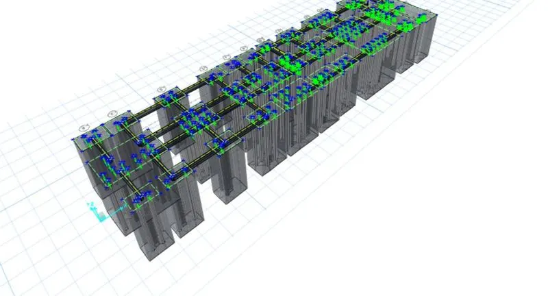
- The following stage is drawing pile caps; to do this, use the Quick Draw Slab command to pick the pile caps and add them.
- Pile caps and piles should both be referred to as stiff materials.
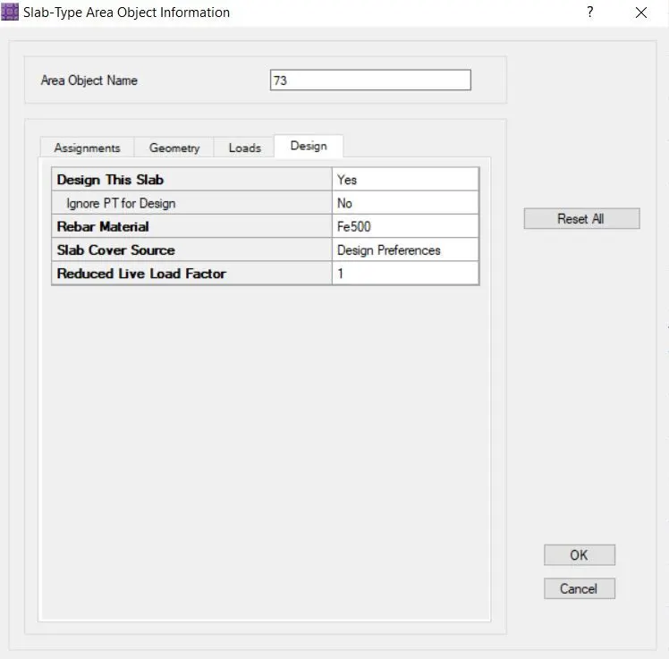
- Changed the rebar's material to Fe 500 after selecting the pile caps.
- Next, select Draw, and Draw Point. A window will appear; mark the locations of the piles there.
- Select the fast draw again, this time around the pints, and then choose the property circular slab add piles dia in this instance 0.5m and add to the points.
- Pick out these heaps and look again for the rebar components.
- Currently, we must define each pile as a spring pile. To do this, go to define choose soil spring properties to add a new property, click on compression only, and then enter the K=EA?L calculation value.
- Select all of the piles, then select Assign, Support Data, Spring Properties, and Assign.
- Enter define, choose the defined beam, and define the tie beams whose thickness should be equal to the thickness of the pile caps.
- Check the design choices to see whether the rebar material is Fe 500.
- Go to define and define the SLS and uls load combinations.
- visit the design and design preferences page.
- Run the Analysis after saving the model.
- Shapes with deformations demonstrated how minimal they are.
- Assign the decorative strips
- Conduct the analysis.
- Shape deformation: all values are less than 25 mm; this is acceptable.
- Now choose "show" and then "punching shear"; the numbers we have are less than 1, thus everything is OK.
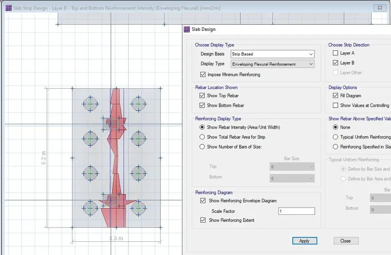
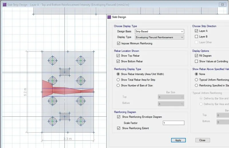
- Now pick slab design under show.
- Every aspect of the strengthening will be disclosed.
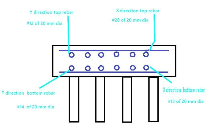
- Maximum Reinforcement was used for X Direction Middle Strip.
For Top:- 29834 mm^2/m=29834/3.3=9041 mm^2=28 nos. 20 mm dia are provided
For Bottom-13326mm^2/m=4038 mm^2=13 nos. 20 mm dia are provid
For layer Y direction
maximum Reinforcement was
For Top:- 19926= 3831mm^2/m=12 nos of 20 mm dia are provided
For Bottom-22784mm^2/m=4398 mm^2=14 nos 20 mm dia are provided