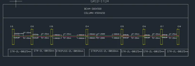
Project 2_Design & Analysis of a Hostel building at Guwahati, Assam
GIVEN DATA:
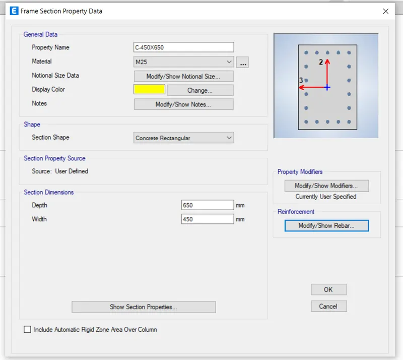
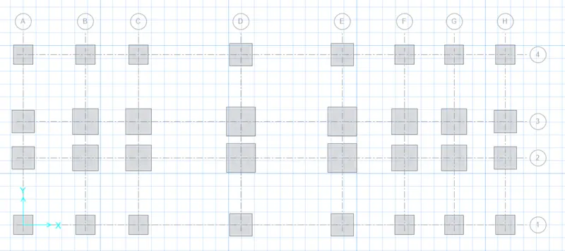
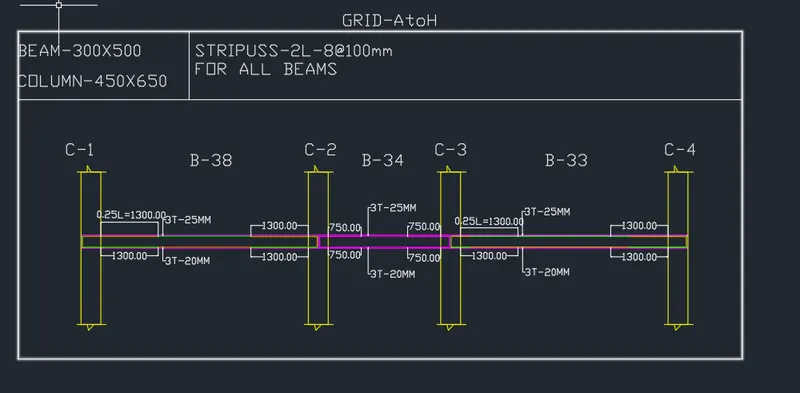
Column of size:- 450mm *600 mm & 600mm*450m m
pile has a load carrying capacity of 280kN
Pile length-16 m and dia of pile -500 mm
SBC-150kN/m^2
Solution:
- Number of piles=Total Axial load/pile capacity=(1.5DL+1.5LL)/280= numbers
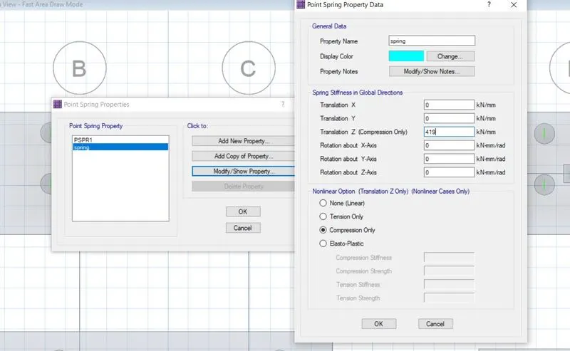
- Piles in the springs are defined as spring so for that the spring constant
K=EA/L
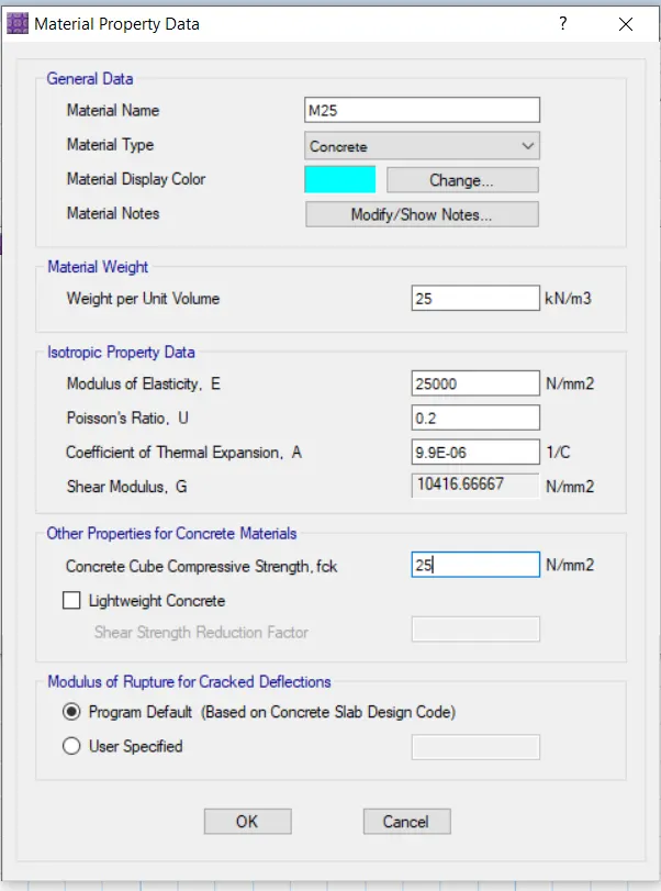
E=5000(fck)^0.5=5000(25)^0.5=25000 N/mm^2
Area of pile =22/7*d^2=3.142*(500)^2/4=196375m^2
L-10000m
K=25000*0.7855/16=306835.9N/mm==419.
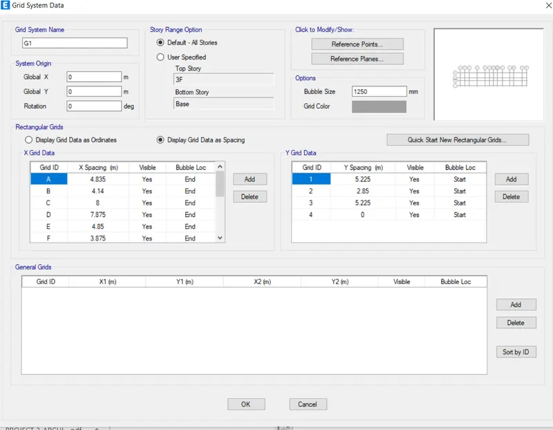
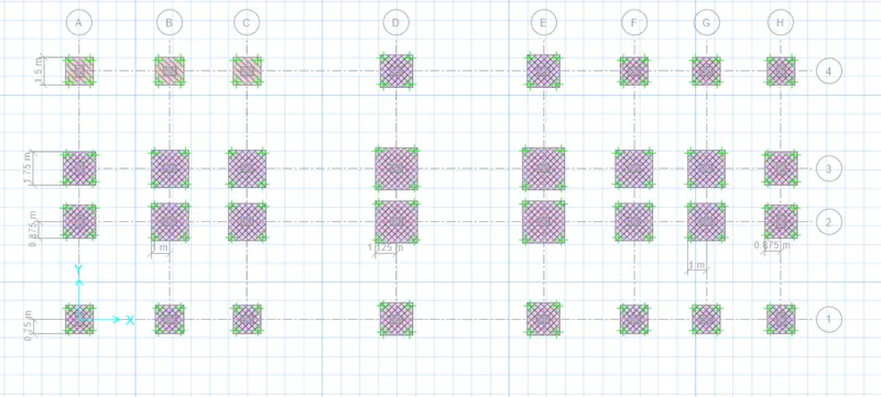
- Spacing of the piles as per clause number 6.6.2 of IS 2911 the spacing between the piles =2.5dia of the piles =2.5*500=1250mm
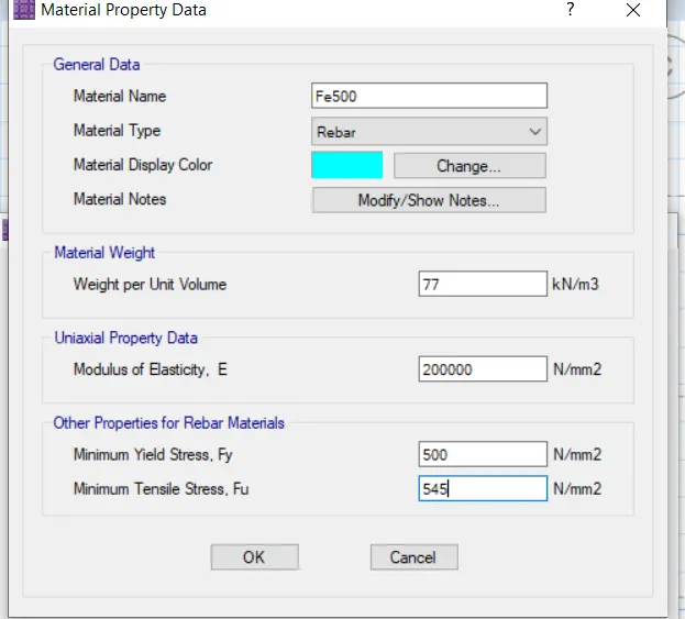
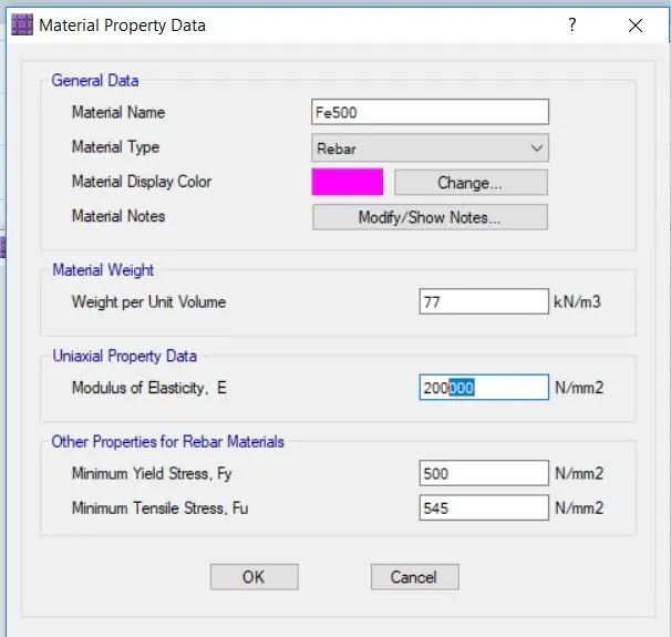
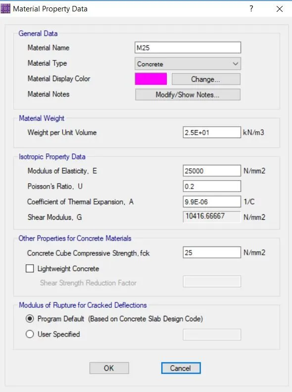
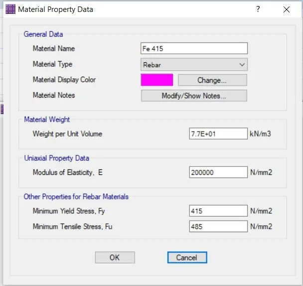
- Now in the next step we have to define the material properties for go to define and define the material properties of Concrete and Reinforcement properties Fe500 & Fe 415.
- Select the values .
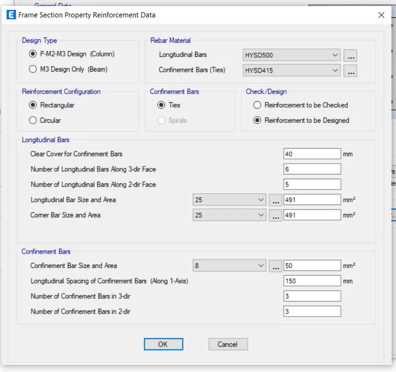
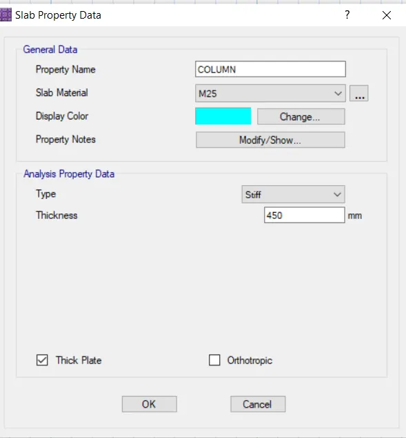
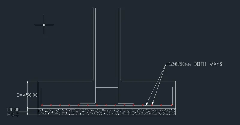
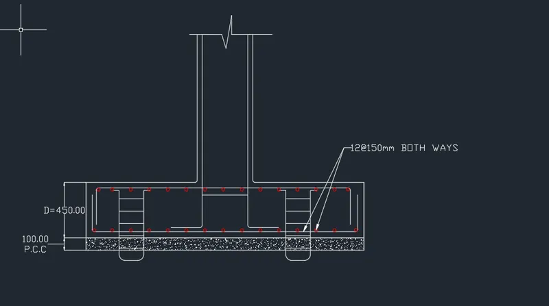
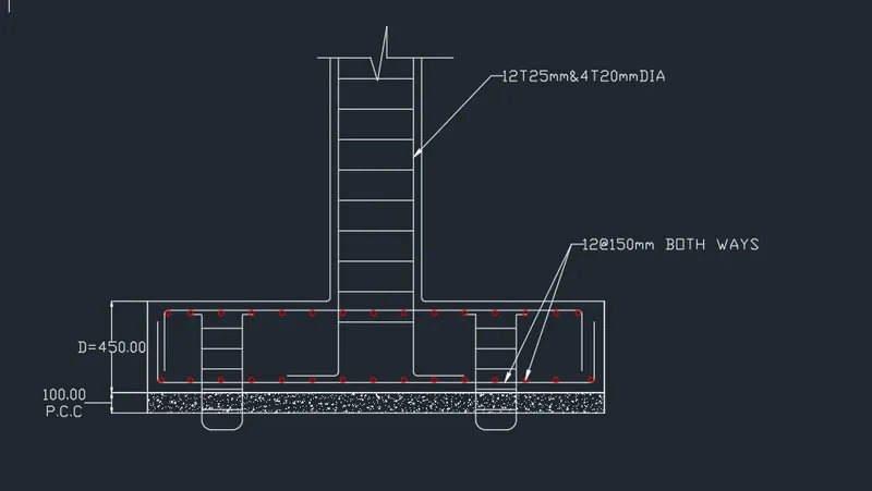
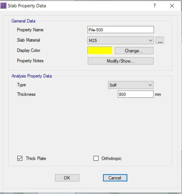
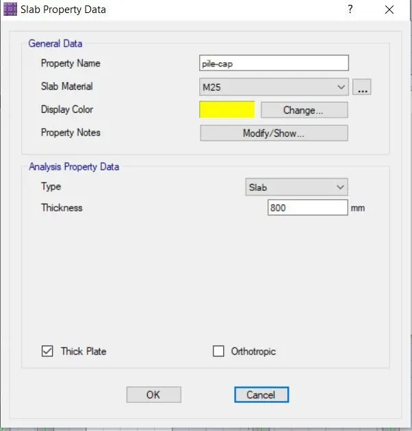
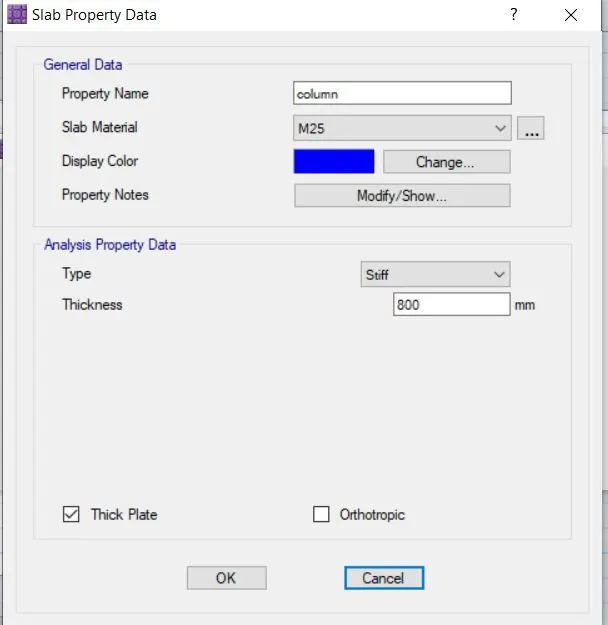
- Go to define section properties and define pile caps ,pile Dia , and column
- Add new , defined pile cap pile 500 as Mat , and Column as Stiff.
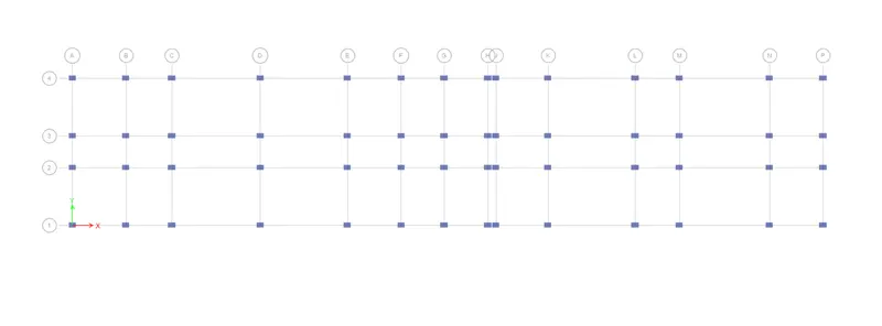
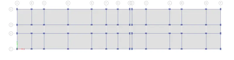
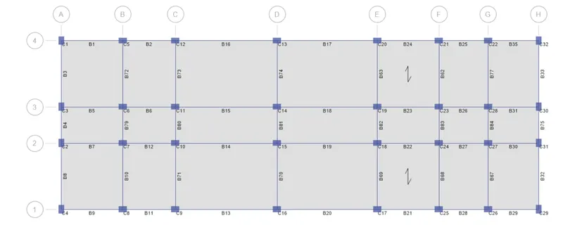
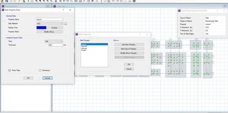
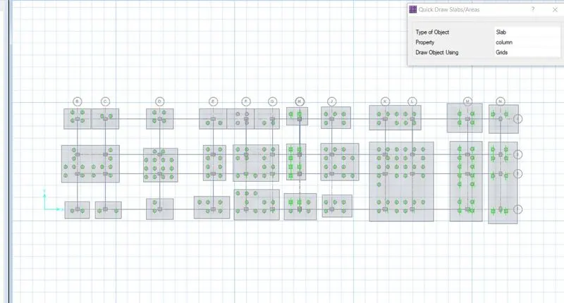
- Click on the quick draw around the plots a window will open there insert the columns sizes and these columns to their specified positions. Columns should be stated as stiff material.
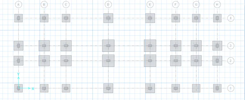
- In the next step pile caps needs to be drawn for that go to Quick draw slab command select pile caps and add it. Piles and pile cap should be stated as stiff material.
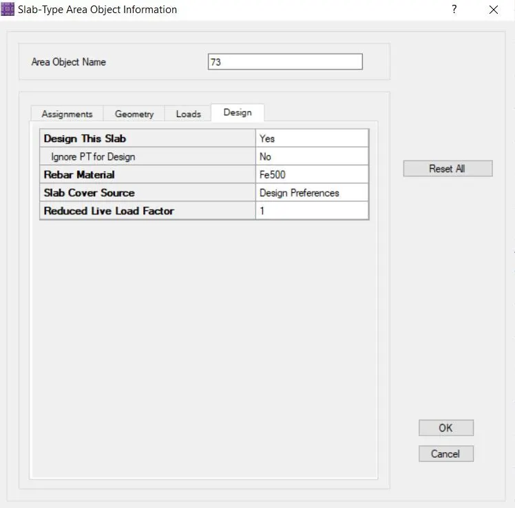
- Select the pile caps and changed the rebar material as Fe 500 .
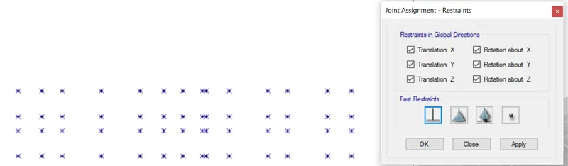
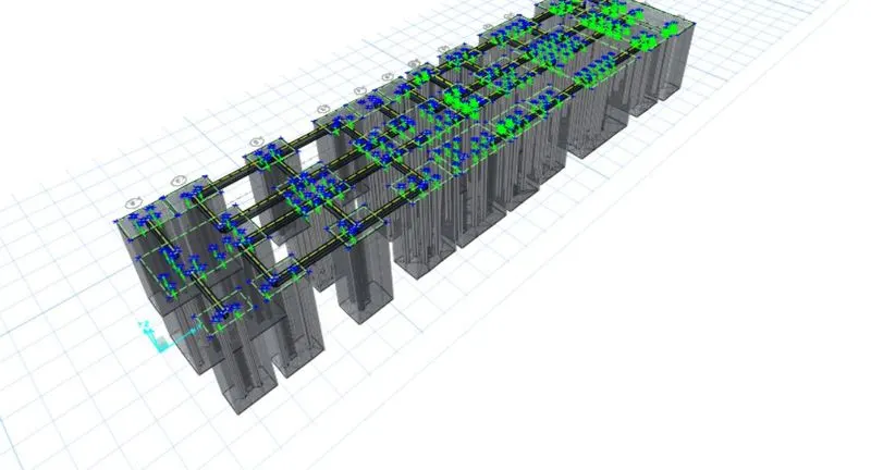
- Next go to draw and draw point and a window will open up there draw the points where piles are to be drawn.
- Now again select the quick dfaw around the pints there select the property circular slab add piles dia in this case 0.5m and add to the points. Select these piles and again check for the rebar materials.
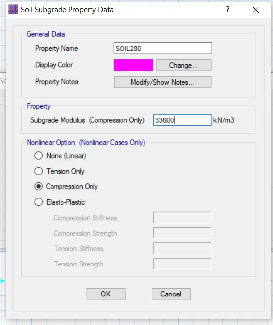
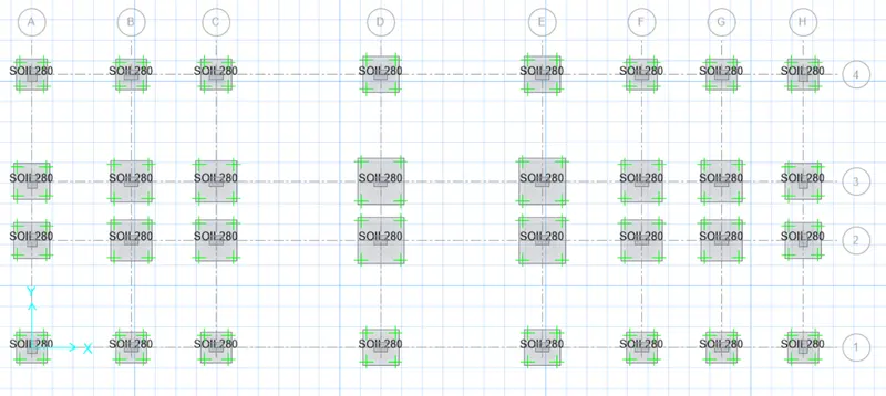
- Now we have to define all the piles as spring for that go to define
- select soil spring properties add new property there click on compression only and add the calculation value of K=EA?L.
- Select all the piles and go to assign and select support data and select spring properties and assign it.
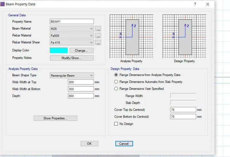
- Go to define and select the define beam and define the tie beams whose thickness should be as of pile caps.
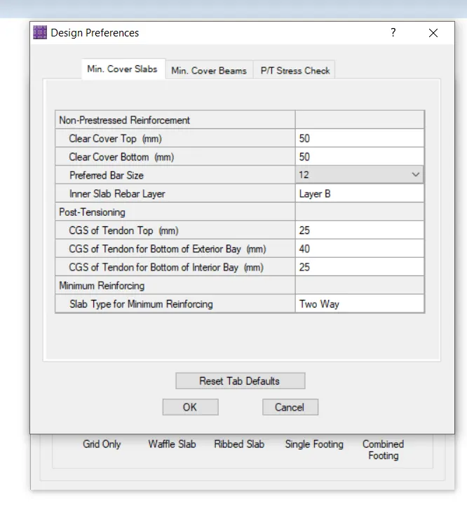
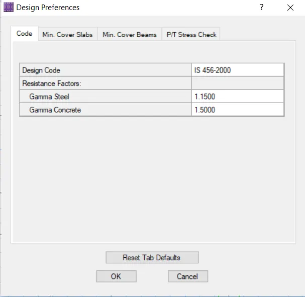
- Check weather the rebar material is Fe 500 under design preferences
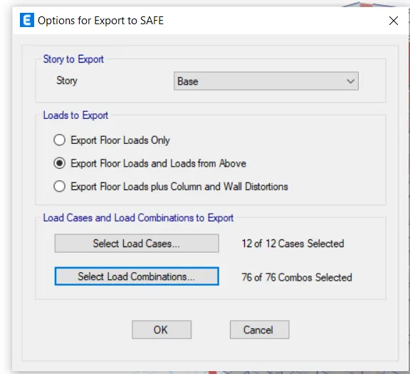
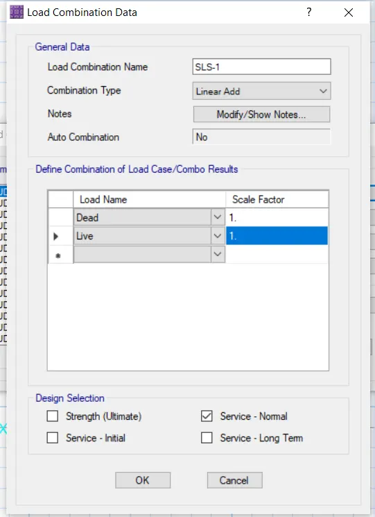
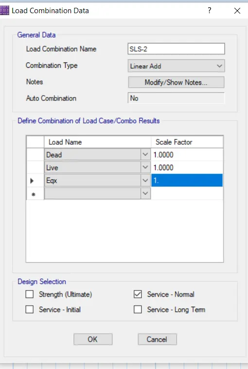
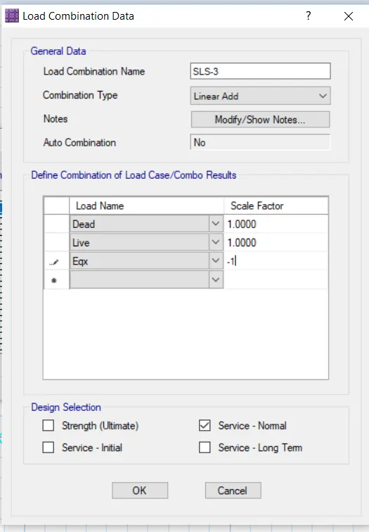
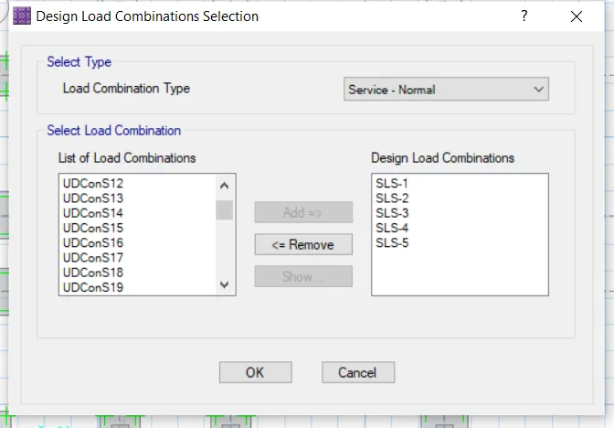
- Go to define and define the load combinations sls and uls
- Go to design and design preferences
- Save the model and run the Analysis
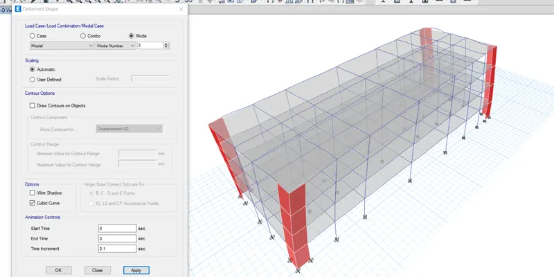
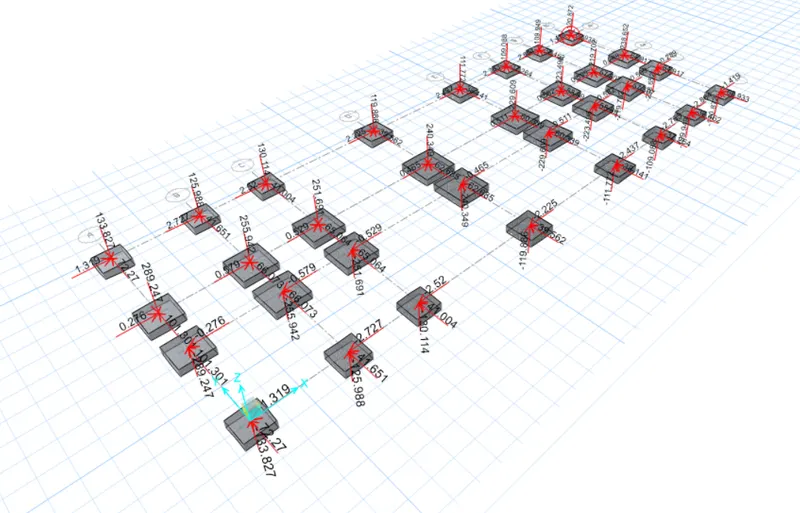
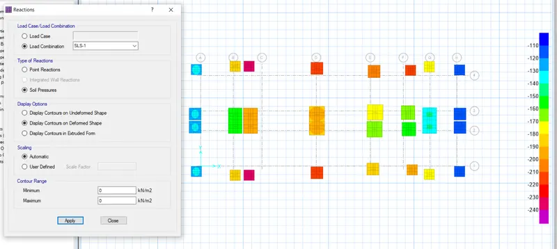
- Deformed shapes showed that deformations are negligible
- Assign add the design strips
- Run the analysis
- Deformed shape all the values are less than 25 mm hence ok.
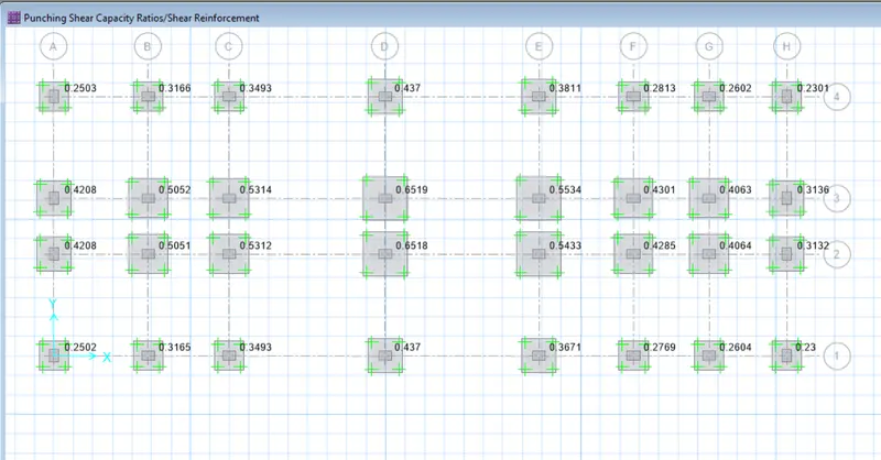
- Now go to display and click on the punching shear the values we have go are less than 1 hence ok.
- Now go to display and select slab design.
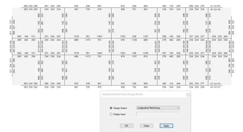
- All the reinforcement details will be available
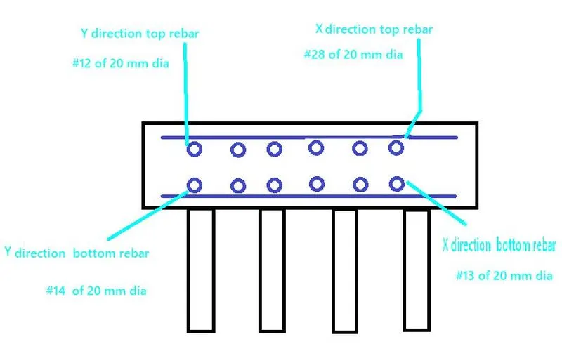
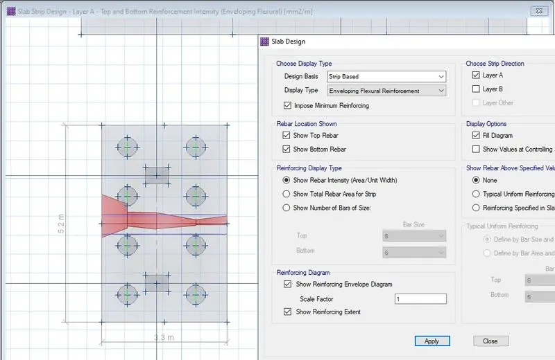
- For X DIRECTION MIDDLE STRIP
maximum Reinforcement was
For Top:- 29834 mm^2/m=29834/3.3=9041 mm^2=28 nos. 20 mm dia are provided
For Bottom-13326mm^2/m=4038 mm^2=13 nos. 20 mm dia are provided
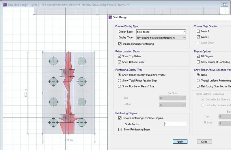
- For layer Y direction
maximum Reinforcement was
For Top:- 19926= 3831mm^2/m=12 nos of 20 mm dia are provided
For Bottom-22784mm^2/m=4398 mm^2=14 nos 20 mm dia are provided
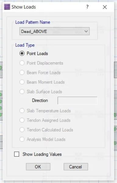
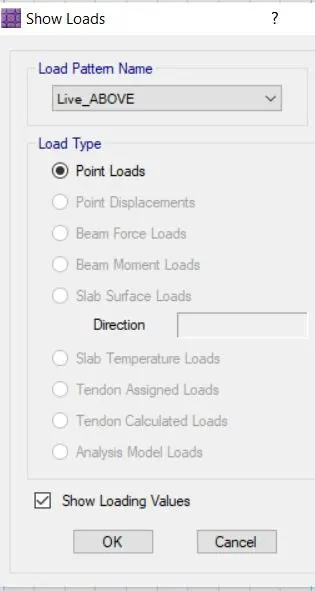
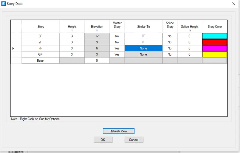
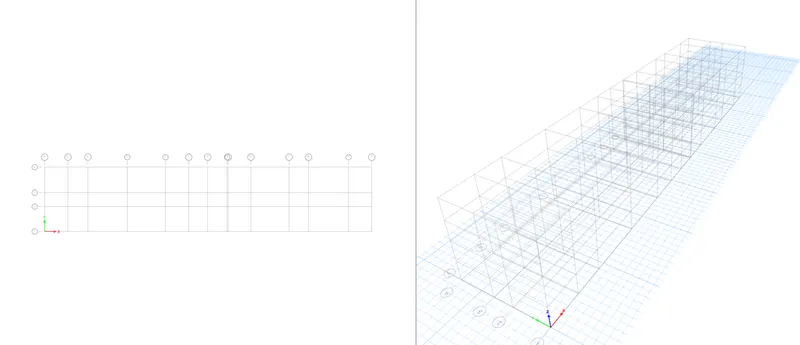
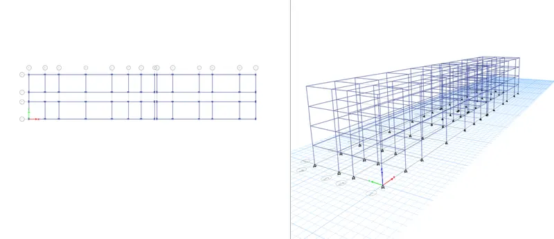
1.In this project, participants will get to experience the entire design process from modelling, analysis, design, and preparation of construction drawings. The architectural drawings of a G+3 RCC building is provided. The following information on the building is to be used:
- Location – Guwahati, Assam
- Function – Hostel block in an academic institute