Sketch a G+1 residential plan according to Vaastu Shastra and Calculation of Loads as per IS code
AIM:
To Sketch a G+1 floor residential plan, according to Vaastu Shastra, and to provide the names of the structural drawings required for construction.
INTRODUCTION:
This project is based on sketching a plan of G+1 residential building, according to Vaastu Shastra. Names of the structural drawings required for the construction is provided.
PLAN:
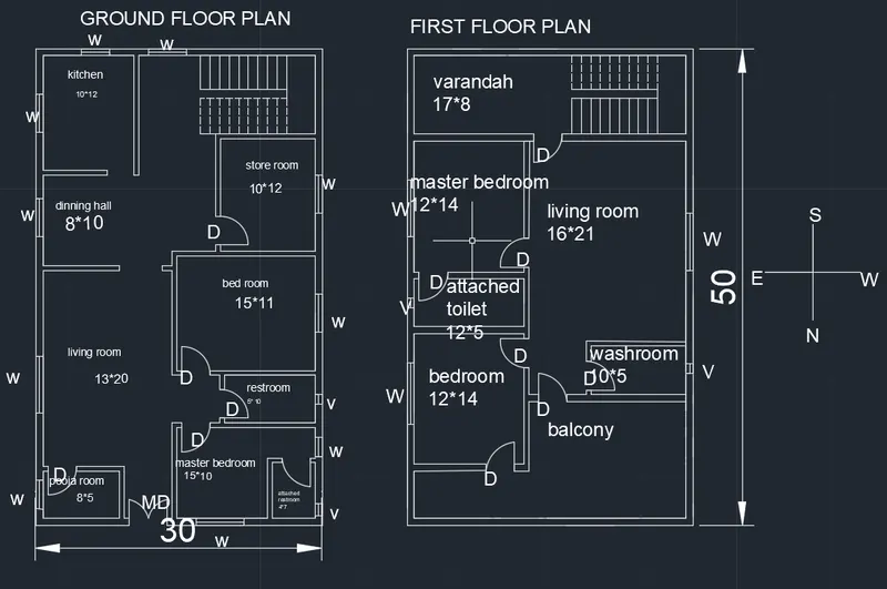
The plan of the structure is given. Both the ground floor plan and first floor plan is provided.
DATA IN PLAN:
- All dimensions in the plan are given in feet.
- The width is 30 feet and the length of the building is 50 feet.
- Thickness of the main wall is 9” and the thickness of the partition wall is 4.5”.
- The house is north faced building.
- Height of each floor is 12feet, and it is a G+1 structure and the total height of the building is 24 feet. The height of parapet wall is 3 feet and the total height of the building is around 27feet.
LOAD CALCULATION:
DEAD LOAD CALCULATION:
The dead load of a floor or of a roof is generally given in terms of load per unit area (i.e. pounds per square foot or kilo newtons per square meter).
The total dead load on a building is determined by adding together all of the various dead loads of the building's elements.
COLUMN:
- Vertical element in a structure that supports the beam and slab.
- It transmits the load from beams and slab to the floor or foundation.
- Column is a compression member.
- All columns are connected to footings at the bottom point.
- In worst case, if column is rested in a beam, than it is called floating column.
- They are designed to resist lateral forces.
- The effective length exceeds three timed the lateral dimension.
- Columns have to be connected to each other by beams for smooth transfer of loads.
Considering the columns to be located in the corners of the plan.
Number of columns in Ground floor =16
Height of each column = 12 feet = 3.65m
The size of the column is considered to be = 0.4m*0.4m
Column 1 is considered as C1, likewise it is listed as C1, C2, C3,…C16
Since the size and the of all the columns are same Dead loads of all the columns are same
C1=C2=C3=C4=….C16
Total volume of concrete = 0.45*0.45*3.65
= 0.739m3
Unit weight of concrete = 25KN/m3
Dead load of column = 25*0.739
= 18.45KN
Number of columns in first floor = 16
Height of each column = 12 feet = 3.65m
The size of the column is considered to be = 0.4m*0.4m
Total volume of concrete = 0.45*0.45*3.65
= 0.739m3
Unit weight of concrete = 25KN/m3
Dead load of column = 25*0.739
= 18.45KN
BEAMS:
- Beam is a horizontal structural member that transfer the load to the column or wall which in turn gets transferred to the foundation.
- Beam provides resistance to bending when loads are applied on it.
- Beam provides resistance to bending when loads are applies on it.
- Beam is a long slender member having relatively longer span than depth.
- Beams are designed to carry the bending moment and shear force of building.
- Beams can be of wood, steel, aluminium, etc., most commonly used material for beam is reinforced cement concrete.
- Beams can be of different shapes rectangular, square, T-beam, H-beam, etc.,
- Most important in a beam is it’s supporting system.
GROUND FLOOR:
Number of beams in ground floor = 25
Beam size = 0.3*0.6m
Each beam in the structure is of different length
B1 = 3m beams = 12nos
B2 = 3.6m beams = 2nos
B3 = 4.5m beams = 6nos
B4 = 1.5m beams = 3nos
B5 = 2.4m beams =2 nos
CALCULATION:
B1:
The length of the beam is 3m
Total volume of concrete = 0.3*0.45*3
= 0.405 m3
Dead load of beam = 25*0.405
= 10.125 KN
B2:
The length of the beam is 3.6m
Total volume of concrete = 0.3*0.45*3.6
= 0.485 m3
Dead load of beam = 25*0.485
= 12.125 KN
B3:
The length of the beam is 4.5m
Total volume of concrete = 0.3*0.45*4.5
= 0.607 m3
Dead load of beam = 25*0.607
= 15.187 KN
B4:
The length of the beam is 1.5m
Total volume of concrete = 0.3*0.45*1.5
= 0.202m3
Dead load of beam = 25*0.202
= 5.0625KN
B5:
The length of the beam is 2.4m
Total volume of concrete = 0.3*0.45*2.4
= 0.324 m3
Dead load of beam = 25*0.324
= 8.1 KN
FIRST FLOOR:
Number of beams in first floor = 24
Beam size = 0.3*0.6m
Each beam in the structure is of different length
B1 = 2.4m beams = 3nos
B2 = 3.6m beams = 12nos
B3 = 4.2m beams = 2nos
B4 = 1.5m beams = 2nos
B5 = 4.8m beams =5 nos
CALCULATION:
B1:
The length of the beam is 2.4m
Total volume of concrete = 0.3*0.45*2.4
= 0.324 m3
Dead load of beam = 25*0.324
= 8.1 KN
B2:
The length of the beam is 3.6m
Total volume of concrete = 0.3*0.45*3.6
= 0.485 m3
Dead load of beam = 25*0.485
= 12.125 KN
B3:
The length of the beam is 4.2m
Total volume of concrete = 0.3*0.45*4.5
= 0.567 m3
Dead load of beam = 25*0.567
= 14.175 KN
B4:
The length of the beam is 1.5m
Total volume of concrete = 0.3*0.45*1.5
= 0.202m3
Dead load of beam = 25*0.202
= 5.0625KN
B5:
The length of the beam is 4.8m
Total volume of concrete = 0.3*0.45*4.8
= 0.648m3
Dead load of beam = 25*0.3648
= 16.2KN
SLAB:
- Slab is a structural element constructed to create a flat surface such as floors, roofs and ceilings.
- Slab is a two dimensional structural component of building having a very small thickness compared to it’s other two dimensional.
- Slabs are supported by beams, columns, walls or by ground.
- It’s primary function is to transfer the load by bending in one or two dimensions.
- Reinforced concrete slabs are used in roofs, floors, ceilings and as decks of bridges.
- Slab may be mounted on either steel or monolithic concrete beams, walls or evenly directly over the columns.
There are different types of slab
- One-way slab
- Two-way slab
Here the ratio of longer length to the shorter length is less than 2 and hence we are providing two-way slab
Length = 15.24m
Width = 9.14m
Thickness of the slab = 0.15m
Size of slab = 9.14*15.24
Volume of concrete = 9.14*15.24*0.15
= 20.89m3
Unit weight of concrete = 25*20.89
= 522.3KN
LIVE LOAD:
Live load is a civil engineering term that refers to a load that can change over time. The weight of the load is variable or shifts locations, such as when people are walking around in a building. Anything in a building that is not fixed to the structure can result in a live load, since it can be moved around
Live load of a residential building as per IS 875 part-2 -1987 = 2.0KN/m2
WIND LOAD:
- If the height of the building is more than 10m, then the building needs to be designed for Wind load
- These horizontal loads are caused by the wind on the structure
- On using lighter materials for construction, Wind load is a must to be considered
- Particularly the structure needs to be of heavy dead weights and get anchored to the ground to resist the wind load
- Wind loads act horizontally towards walls and roof surface
Calculation of Wind load on a structure:
- The intensity of wind load depends upon the velocity of wind, size and height of the building.
- Wind load is considered to act uniformly upto a height of 30m.
- Above 30m the wind load intensity increases.
- Design Wind pressure is calculated using the expression
Pz = 0.6 V₂^2
Where, Pz = Wind pressure @ height z, in N/m^2
Vz = Design wind speed @ height z, in m/s
- Vz is calculated using the formula,
Vz= Vb*k1*k2*k3*k4
Vb = Basic Wind speed
k1= Probability factor (Risk Co-efficient)
k2 = Terrain roughness and height factor
k3 = Topography factor
k4 = Importance factor
CALCULATION:
Pz = 0.6 V₂^2
Vz is calculated using the formula,
Vz= Vb*k1*k2*k3*k4
Vb = basic wind speed
The location of the building is considered to be in chennai
So the basic wind speed in Chennai region is 55m/s
k1= Probability factor (Risk Co-efficient)
k1 = 1.0
k2 = Terrain roughness and height factor
The structure is considered to be present in category 4 and the height of the structure is 8.2m
k2 = 0.8
k3 = Topography factor
k3 = 1.0
k4 = Importance factor
k4 = 1.0
Vz = 55*1*0..8*1*1
Vz = 44m/s
Pz = 0.6*44*44
Pz = 1161.6m/s
RESULT:
Therefore, the Sketching of a G+1 floor residential plan is made according to Vaastu Shastra, and names of the structural drawings required for construction in site is provided.