Project 2_Creating a 3D rendered model for a Residential Building in AutoCad
AIM:
Creating a 3D Rendered Model for a Residential Building in AutoCAD
OBJECTIVE:
To Create 3D model and View of:
Residential Building in AutoCAD
Commands used:
Extrude, Offset, UCS, Box, Union, Subtract, Move, 3D orbit, Loft, Sweep, Cone, Region, Boundary.
INTRODUCTION:
- An Isometric drawing is a 3D representation of an object, room, building or design on a 2D surface.
- One of the defining characteristics of an isometric drawing, compared to other types of 3D representation, is that the final image is not distorted.
- This is due to the fact that the foreshortening of the axes is equal.
- In an isometric drawing, the object appears as if it is being viewed from one corner, with the axes being set out from this corner point.
- Isometric drawings being with one vertical line along which two points are defined.
- Any lines set out from these points should be constructed at an angle of 30 degree.
PROCEDURE
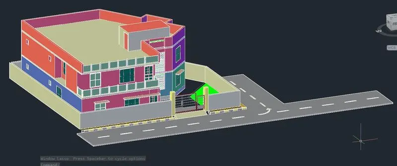
AIM: -CREATE A 3D RENDERED MODEL FOR A RESIDENTIAL BUILDING:
STEPS FOR CREATING A 2D PLAN
Step-1: The Plot of the Residential Building is taken as 60’ x 50’
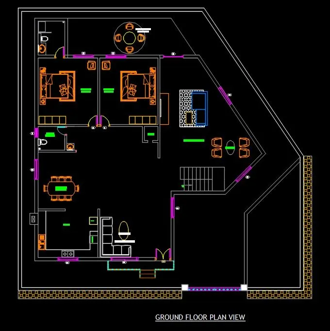
Step-2: Extrude the region to a height of 3 m total height.
Step-3: Use the command ‘BO’ for boundary and create the region i.e, both the region side of the door opening.
Step-4: Draw a rectangle of 1.2 m X 21.1 m, create a line in the center and offset on both sides as 75mm is the width of door opening.
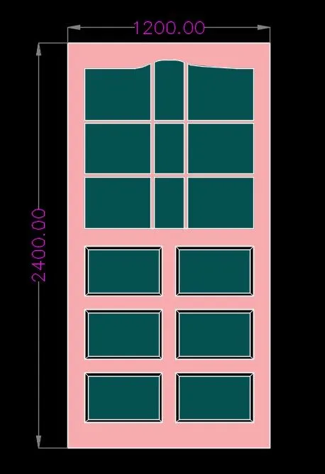
Step-5: Create a rectangle in place of door in the top view, Move the rectangle in Z axis at a height of 7’ from the bottom.
Step-6: Go to front view and draw a line from the center of the moved line of door. Draw slanting line from the total height from the center line intersecting the edge.
Step-7: Next, we draw the window of the size 1.5 x 1.8 m as shown.
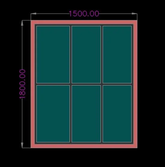
We draw this window using the line command and extruded using the extrude command.
Step-8: Next, we draw the walls using the extrude command as shown.
Next, we use the layers for providing the colors to them.
Next, we attach the created windows to the walls as shown.
Step-9: Next, we use 3dorbit command to see the different views.
Step:10- Ground Floor Plan is ready
Step:11- First Floor Plan is ready
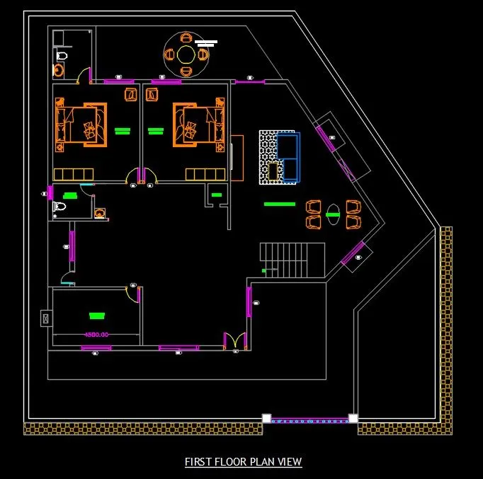
Step:12- Terrace Plan is ready
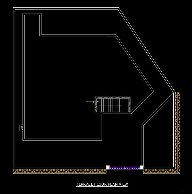
Step-13: Mirror the line to the other side, Draw the horizontal line to join.
Step-14: Trim off the excess line and region with region command in the triangle.
Steo-15: Select the extruded rectangle and with the help of grip bring it down to the level of the triangle base on both sided, Extrude the rectangle of door to a height equal to base of triangle.
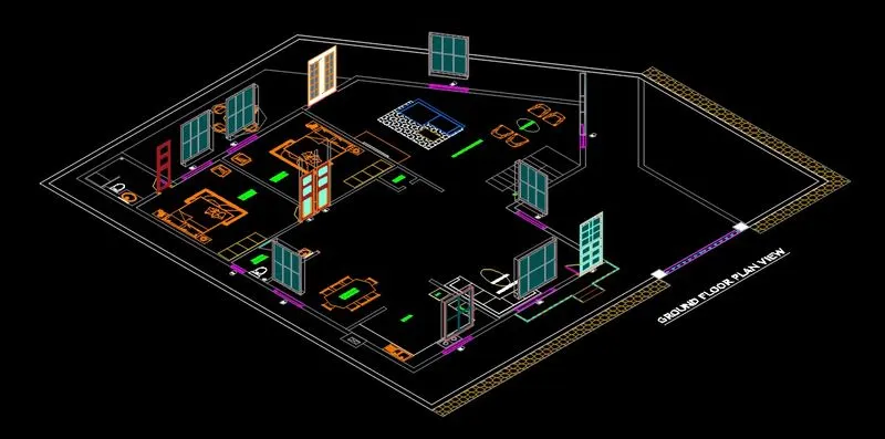
STEPS FOR CREATING A 3D PLAN
Steps-1: In the Left corner click on the settings icon that is the icon of workspace.
Step-2: Select 3D Modelling
Sep-3: Command boundary & in that select region
Step-4: Create boundaries as well as regions of the plan
Step-5: Extrude the regions that are the walls to the height of 3000 from bottom
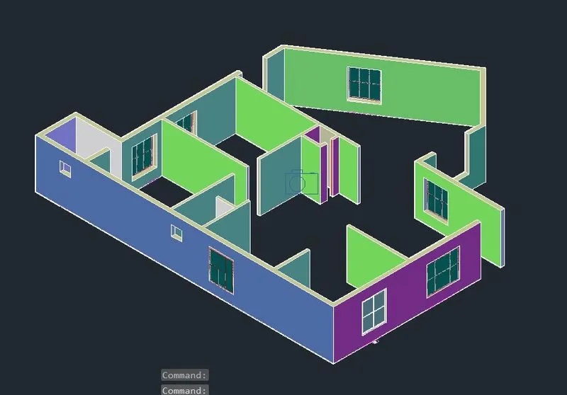
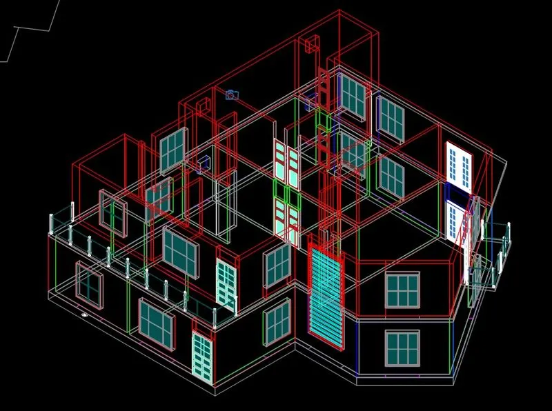
Step-6: Floor to floor height of the building is 3000 mm.
Step-7: Create different type of layers using layer properties like 3D walls, window frames, slab, window, glass etc as desired.
Step-8: Assign colors to each layer separately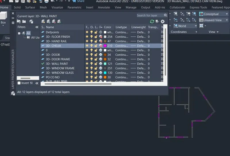
Step-9: Line command is used to draw the doors & Windows.
Step-10: Extrude the window’s & doors to suitable depth
Step-11: Rotated 3D is used to rotate the objects as in windows & doors
Steo-12: Move & copy command is used to move the windows to their desired locations
Step-13: Command polyline at the terrace & create the parapet wall at the top of the building
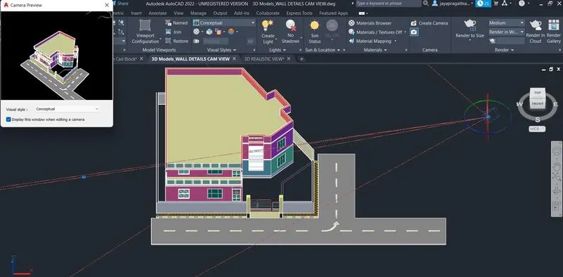
Step-14: Command polyline at the terrace & create the plinth of the building of 600 at the bottom
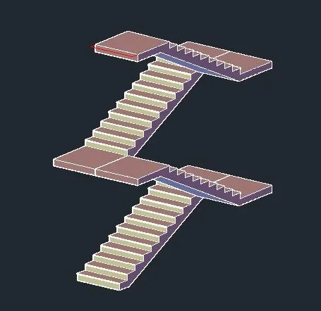
Step-15: Create the staircase & extrude it to the distance of 1200 mm.
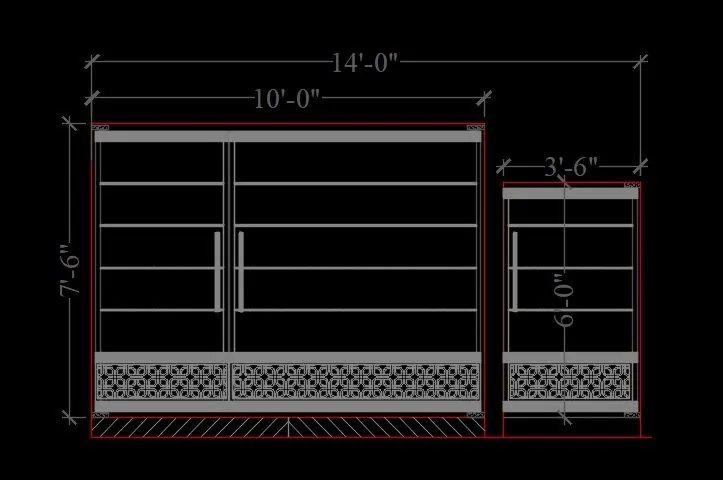
Step-16: Create the Main Gate.
Step-17: Create the mumty separately & place it on the top of the building.
STEPS FOR RENDERING
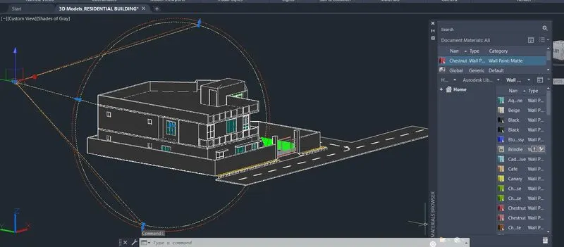
Steps-1: Go to the visualize tab from the ribbon
Step-2: This will give access to the panels like light, sunlight, camera, Animations, Render & Views.
Step-3: Create different views using the camera & Render the building.
Step-4: Place the lights at the desired locations.
RESULT:
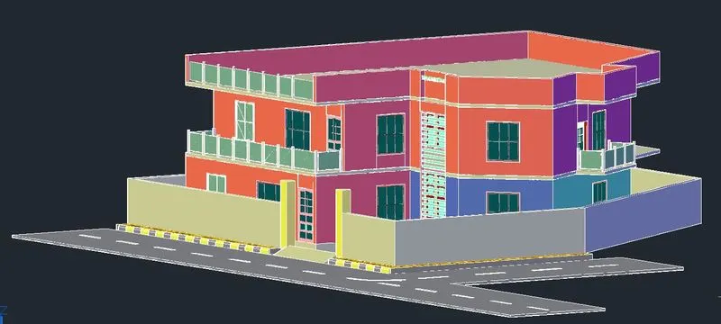
- The 3D Rendered Model for a Residential Building is created using AutoCAD