Project 2_Creating a 3D rendered model for a Residential Building in AutoCad
Aim : To create a 3d model using 3d tools and rendering models using autocad,
Introduction:
- To create a top view of residential plan of size 20'x30' ground floor: by using line rectangle, offset etc commands
- After completion of 2d create a layers of 3d walls 3d windows 3d doors 3d floors etc'
- After that we go to south west isometric and select walls and extrude up to 10' ( afloor height).
- Then we draw adoor cutou of required size & windows of required size.
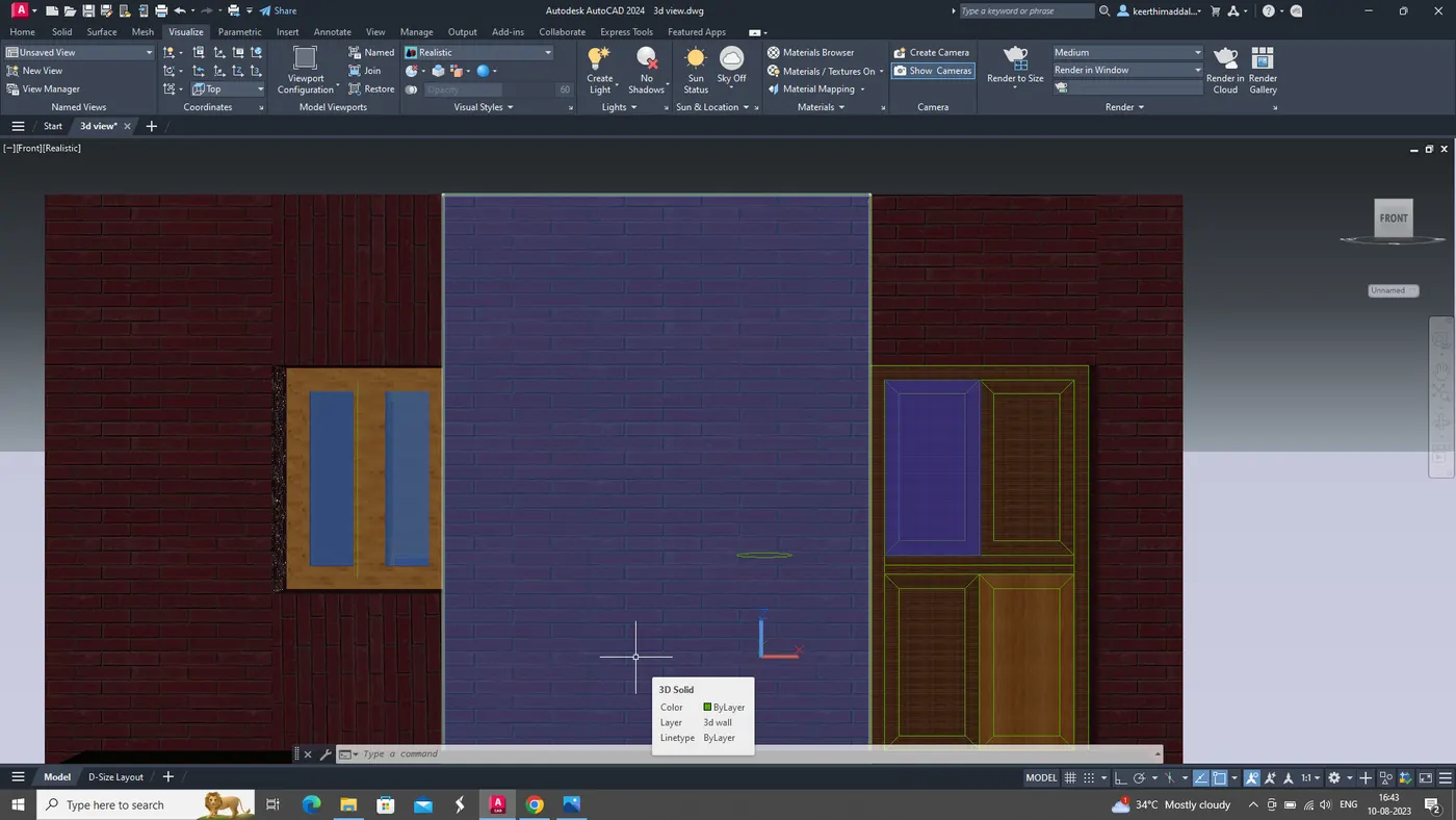
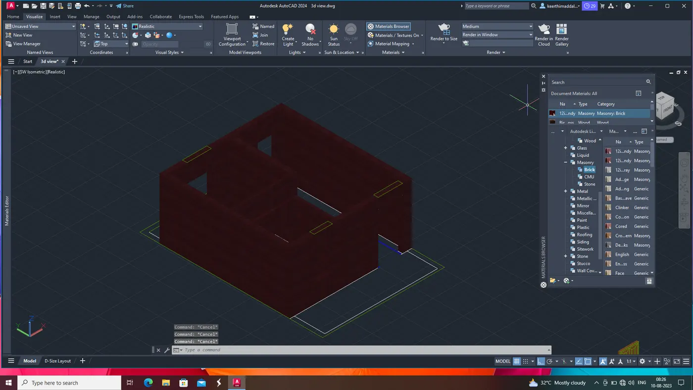
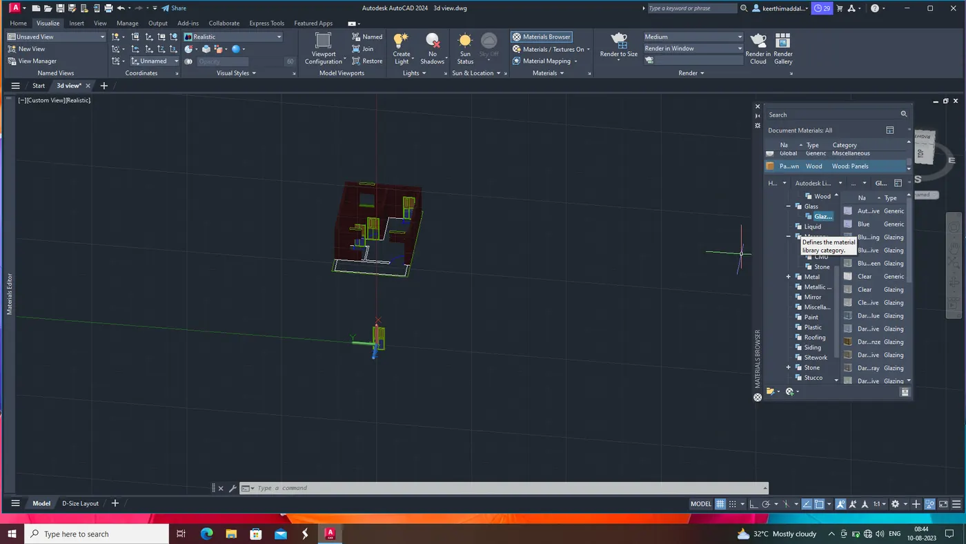
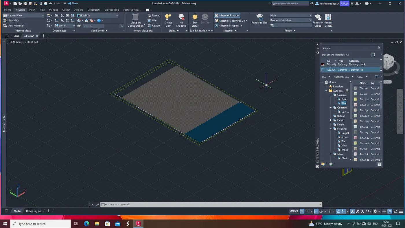
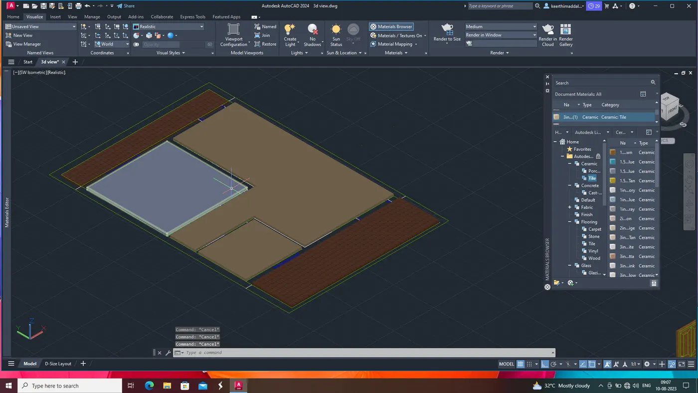
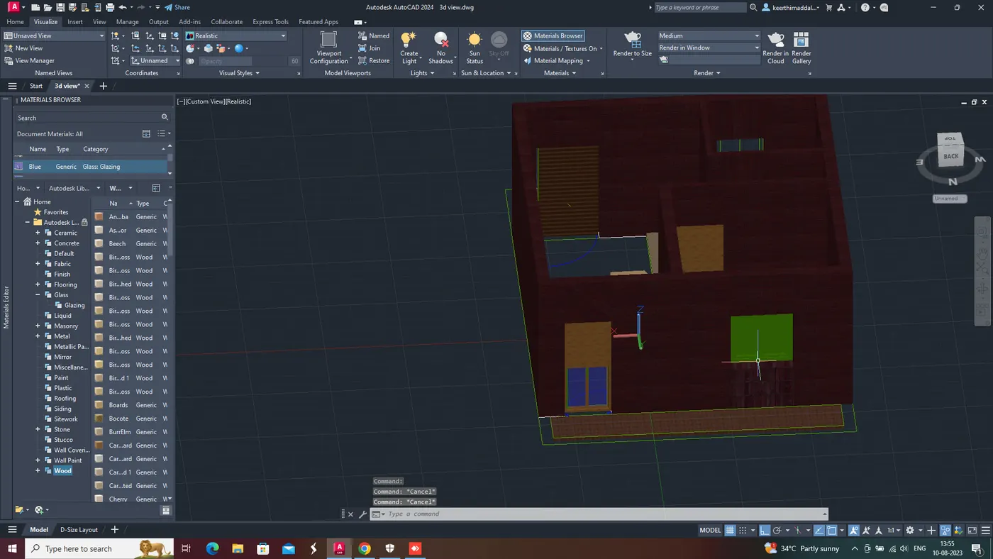
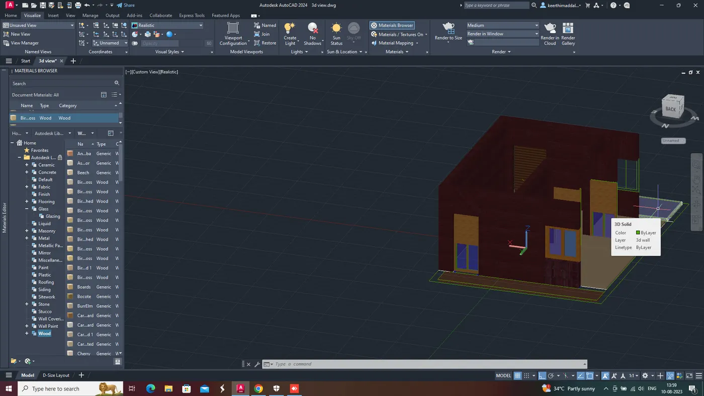
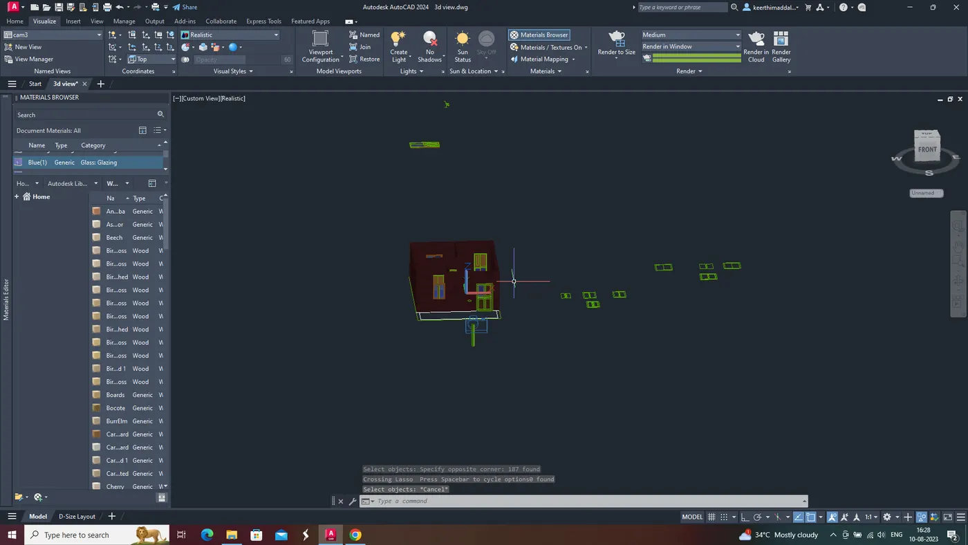
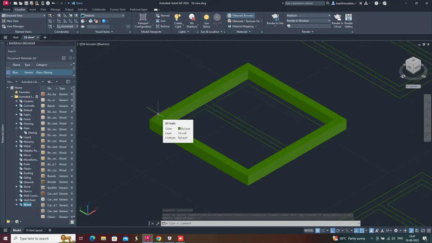
- Then select 3d work space from bottom toolbar and go to visulaise toption from toolbar and select material browser from visualise toolbar and select material i want and assigned where material wants and assign to that.
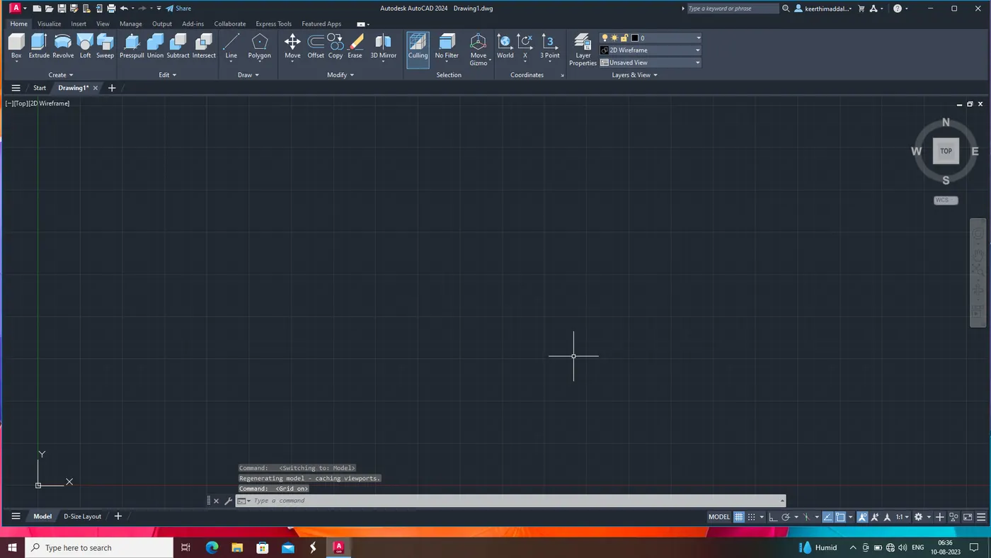
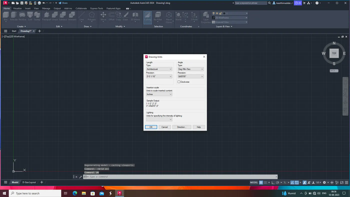
Step1: set units and limits as shown in screen shot
step 2:
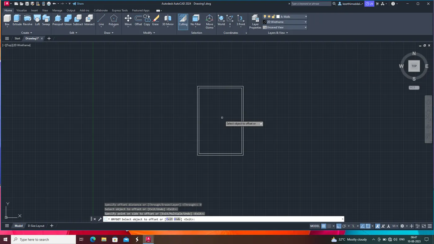
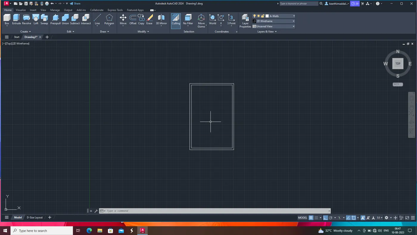
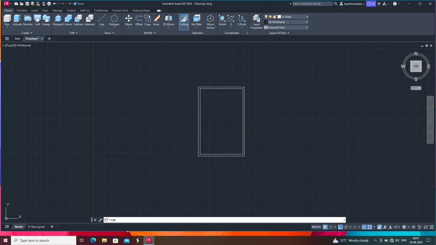
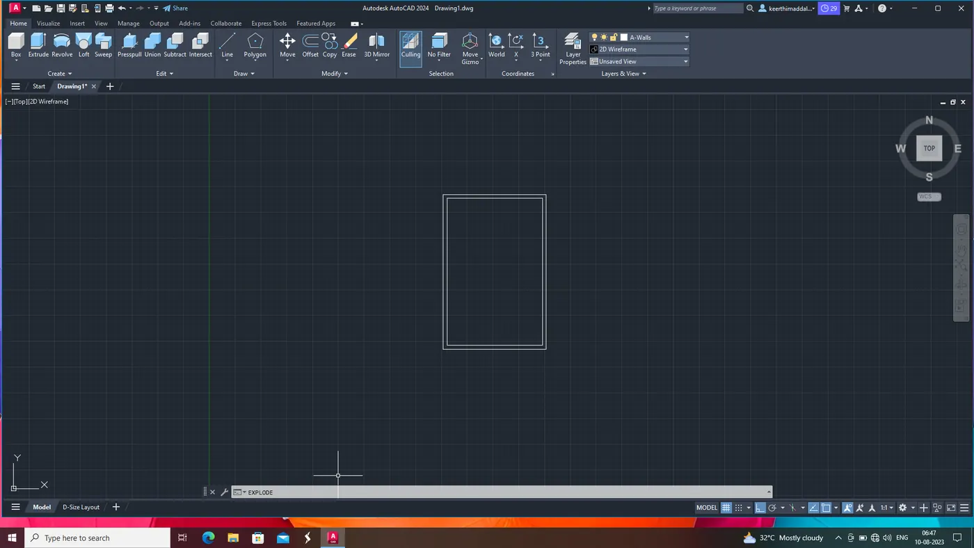
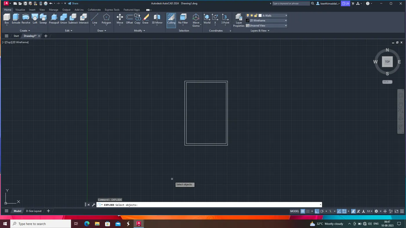
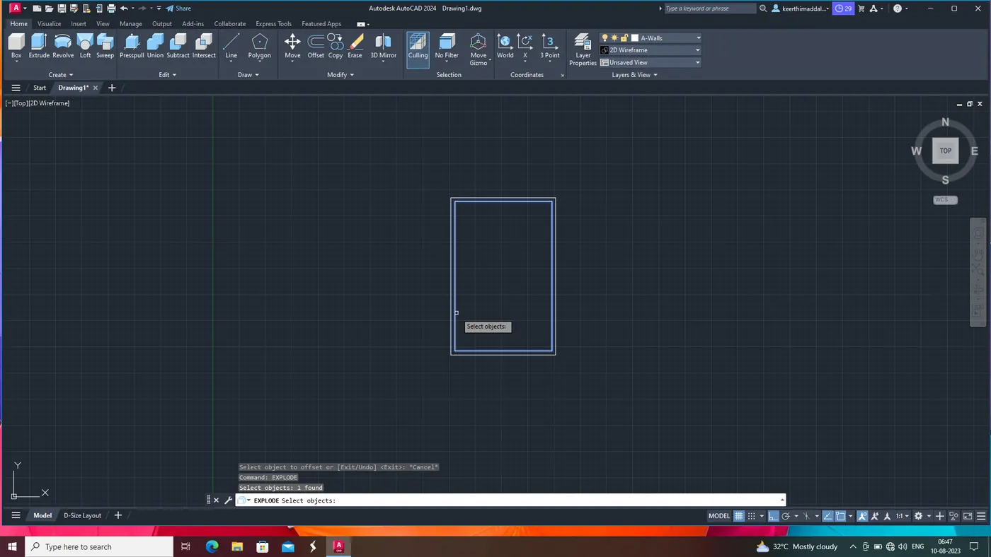
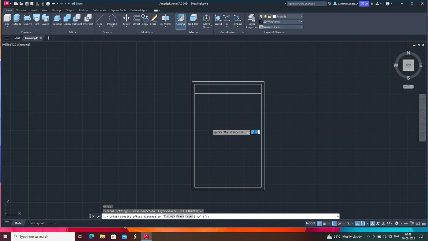
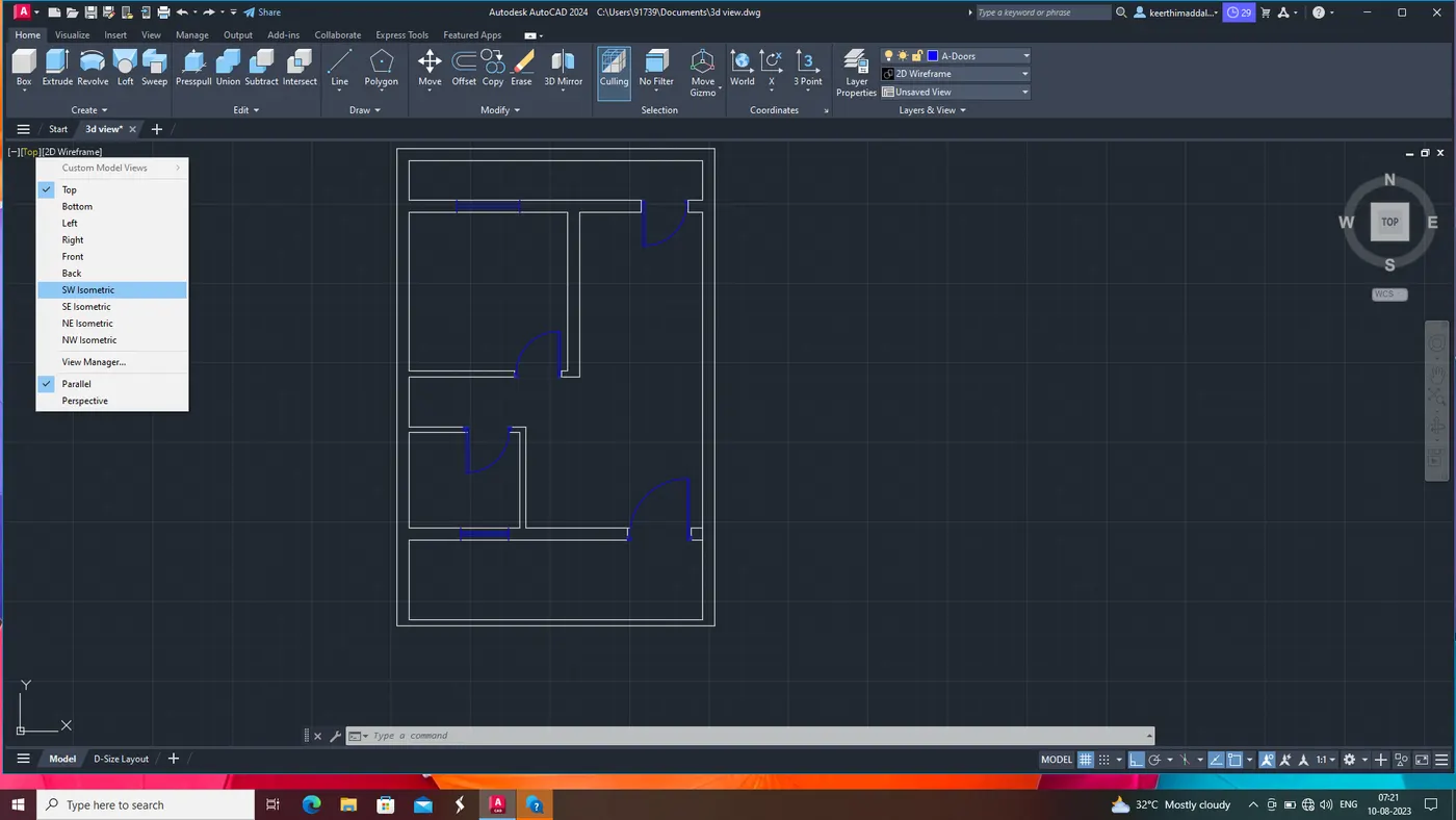
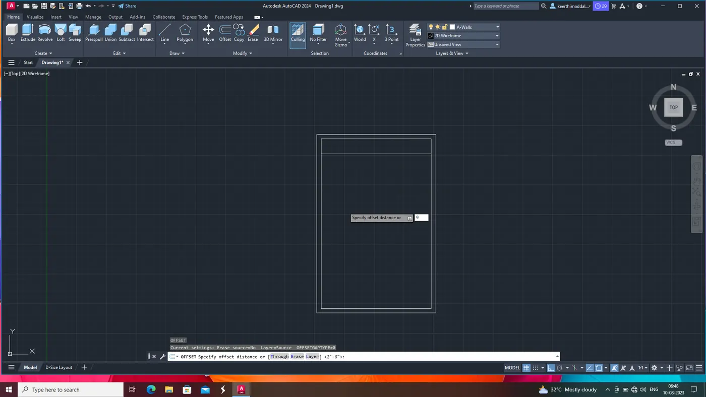
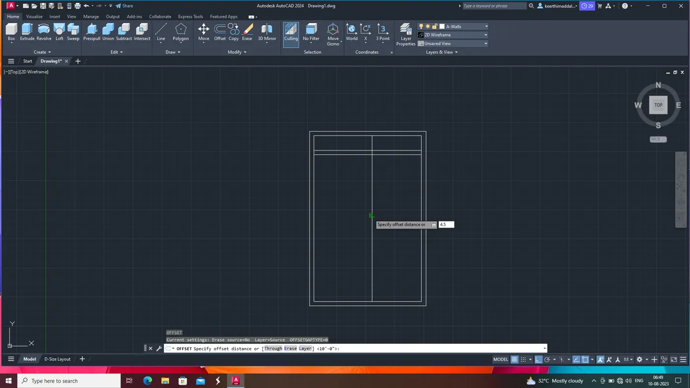
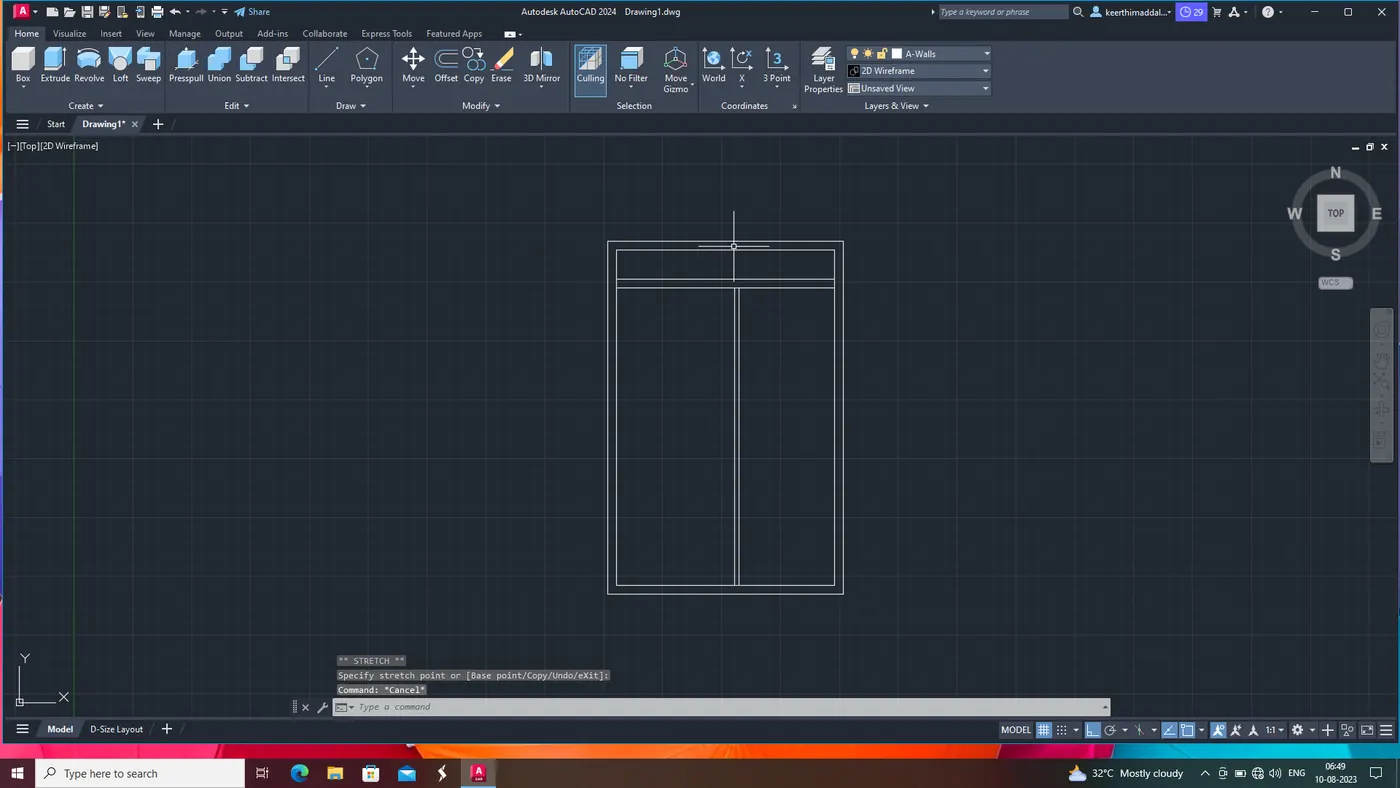
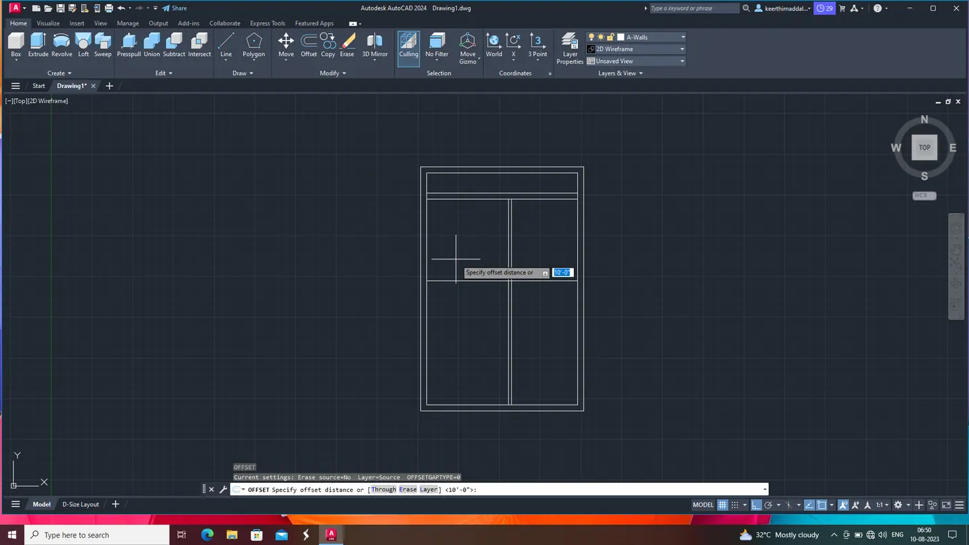
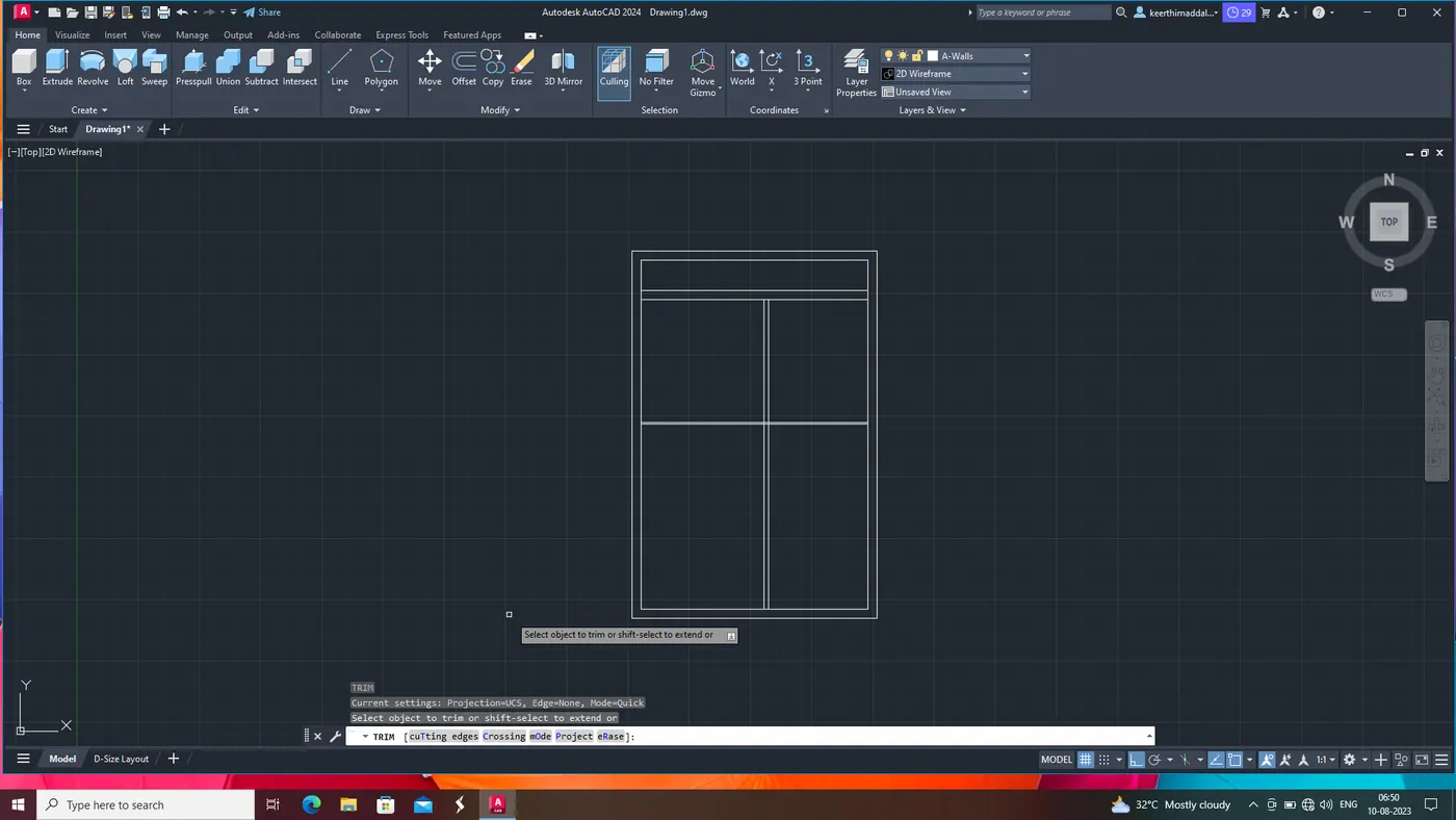
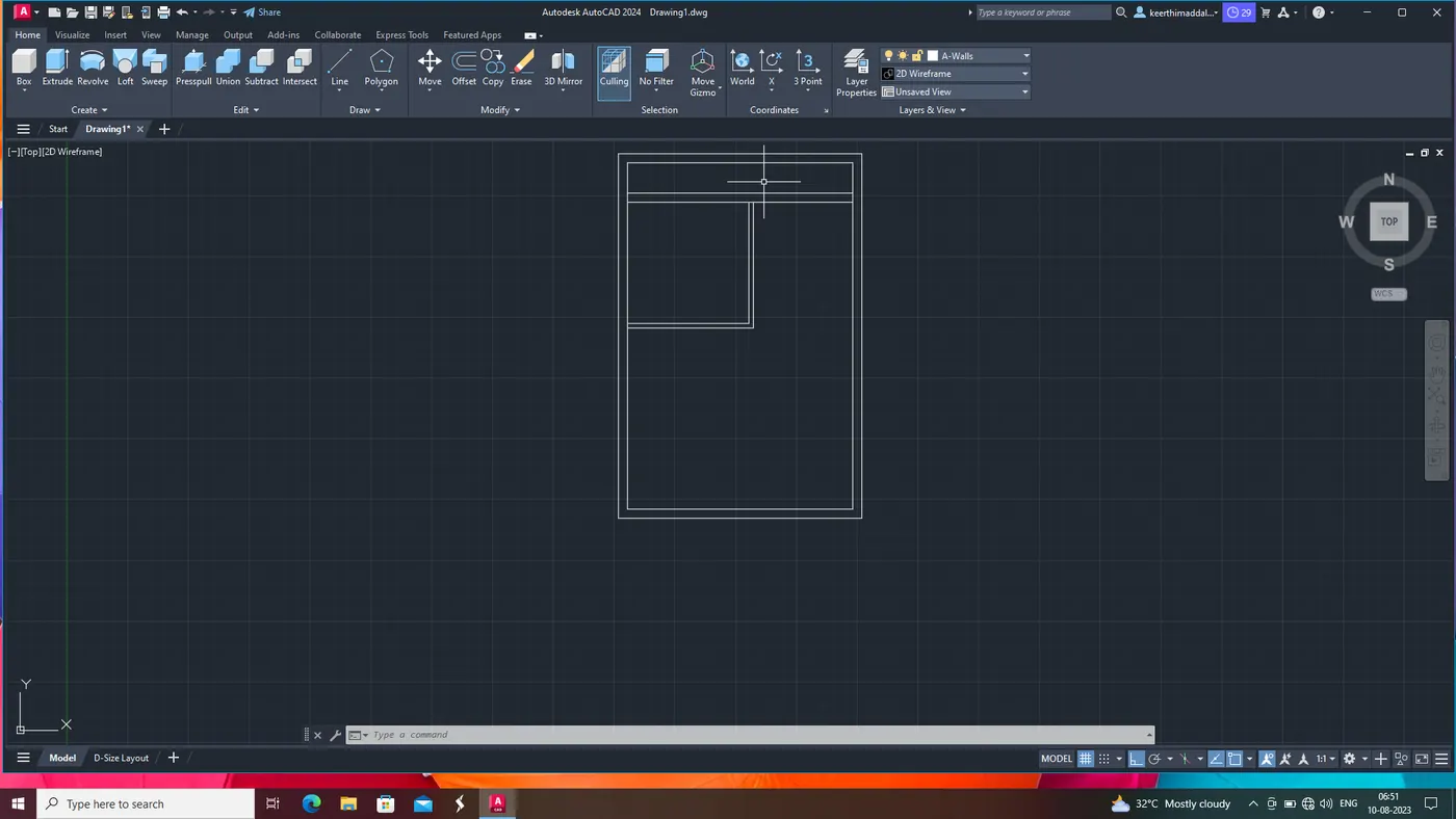
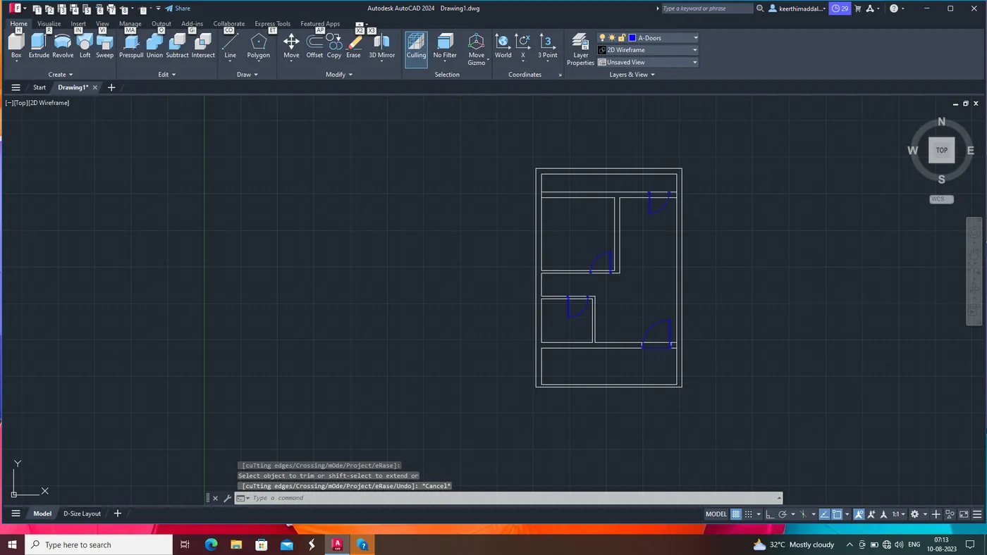
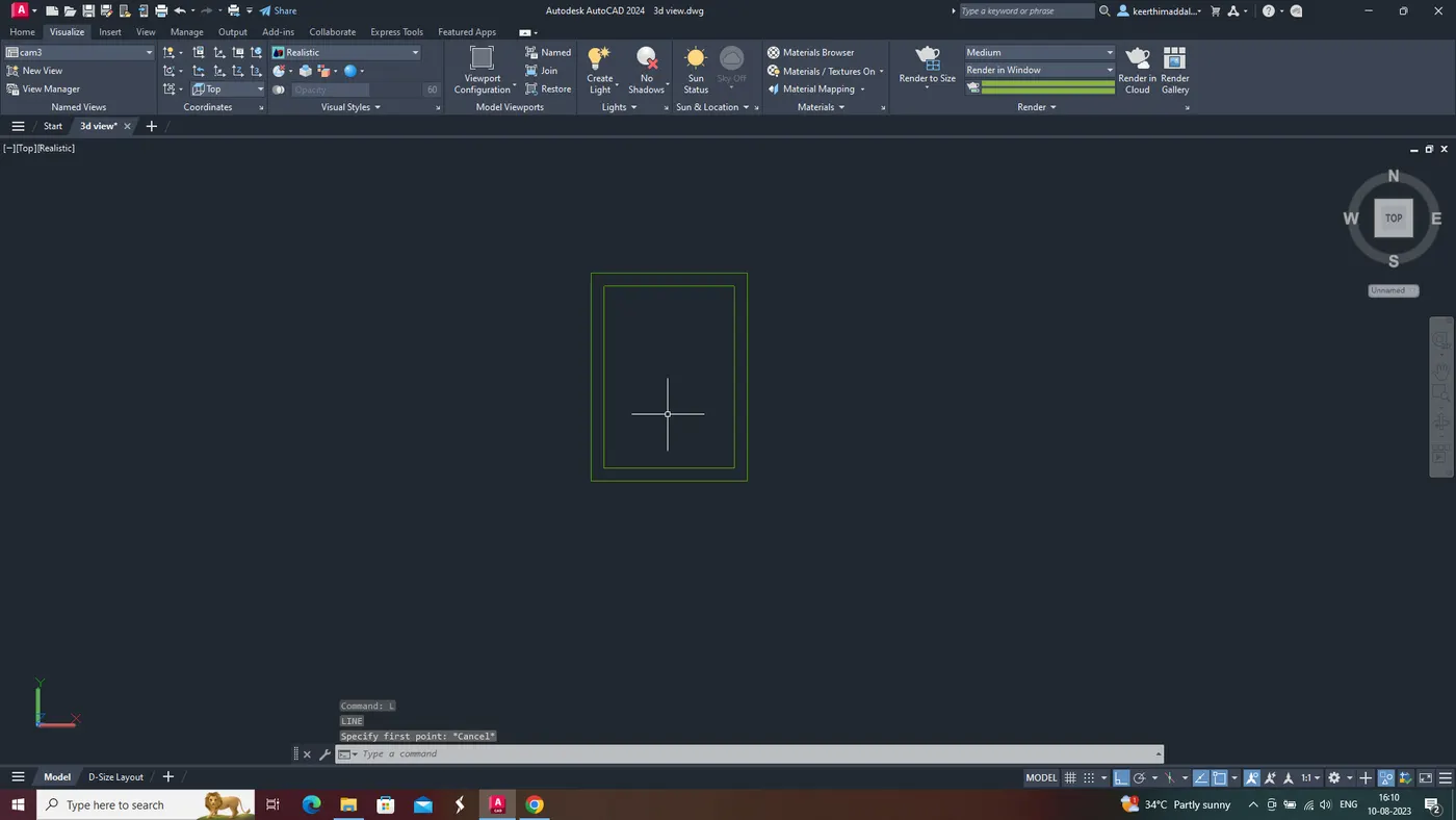
Draw a rectagle of 20'x 30' and draw a offset of 9" then explode the inner rectangle and draw offset of 10',4.5".7',9"in vertical direction as shown in screen shot be;ow

 TH
TH
step3:
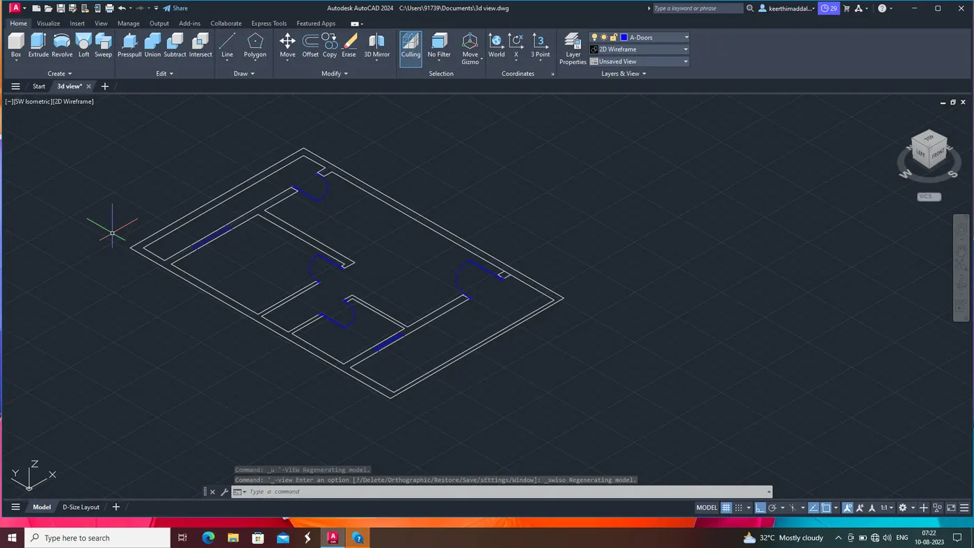
select southwest isometricview fro view and select 3d modeling workspace from downtool bar as shown in screen shots below.
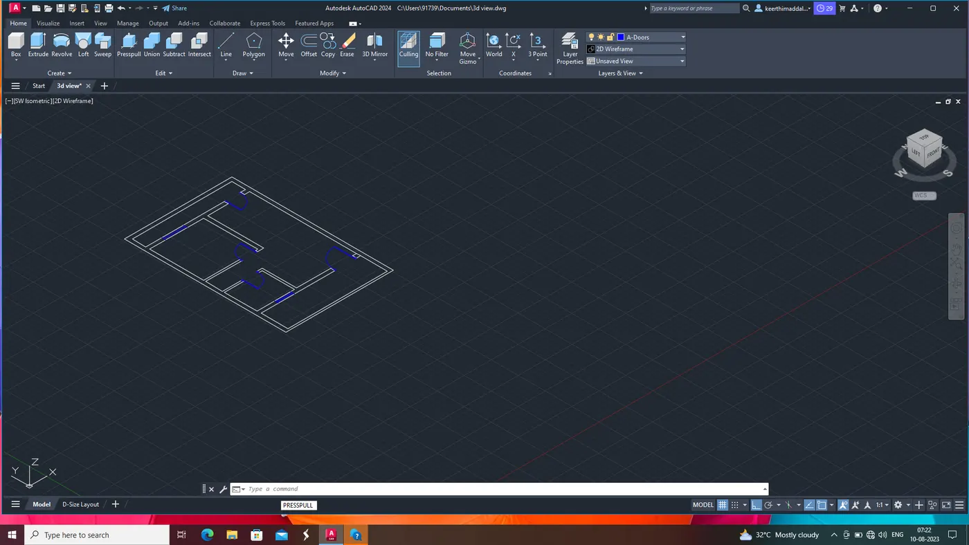
step 4:
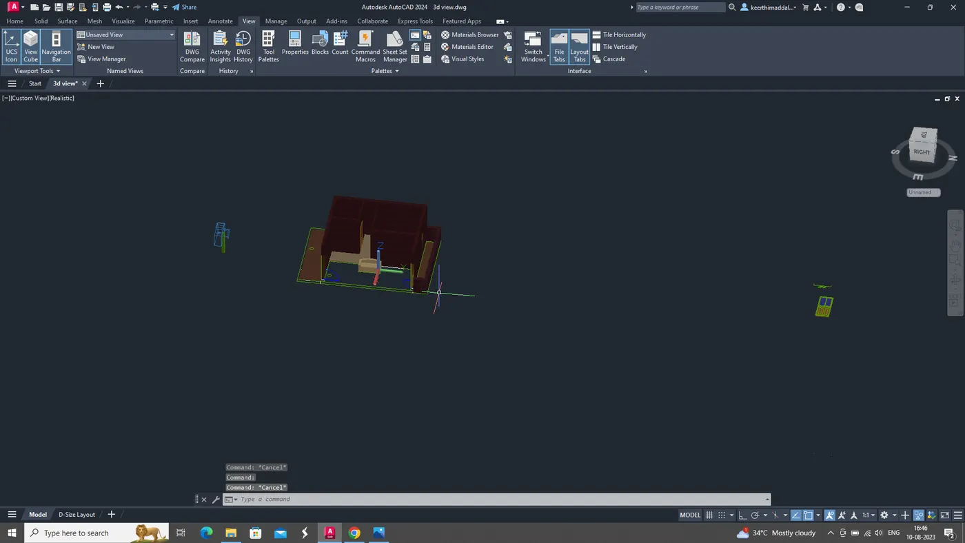
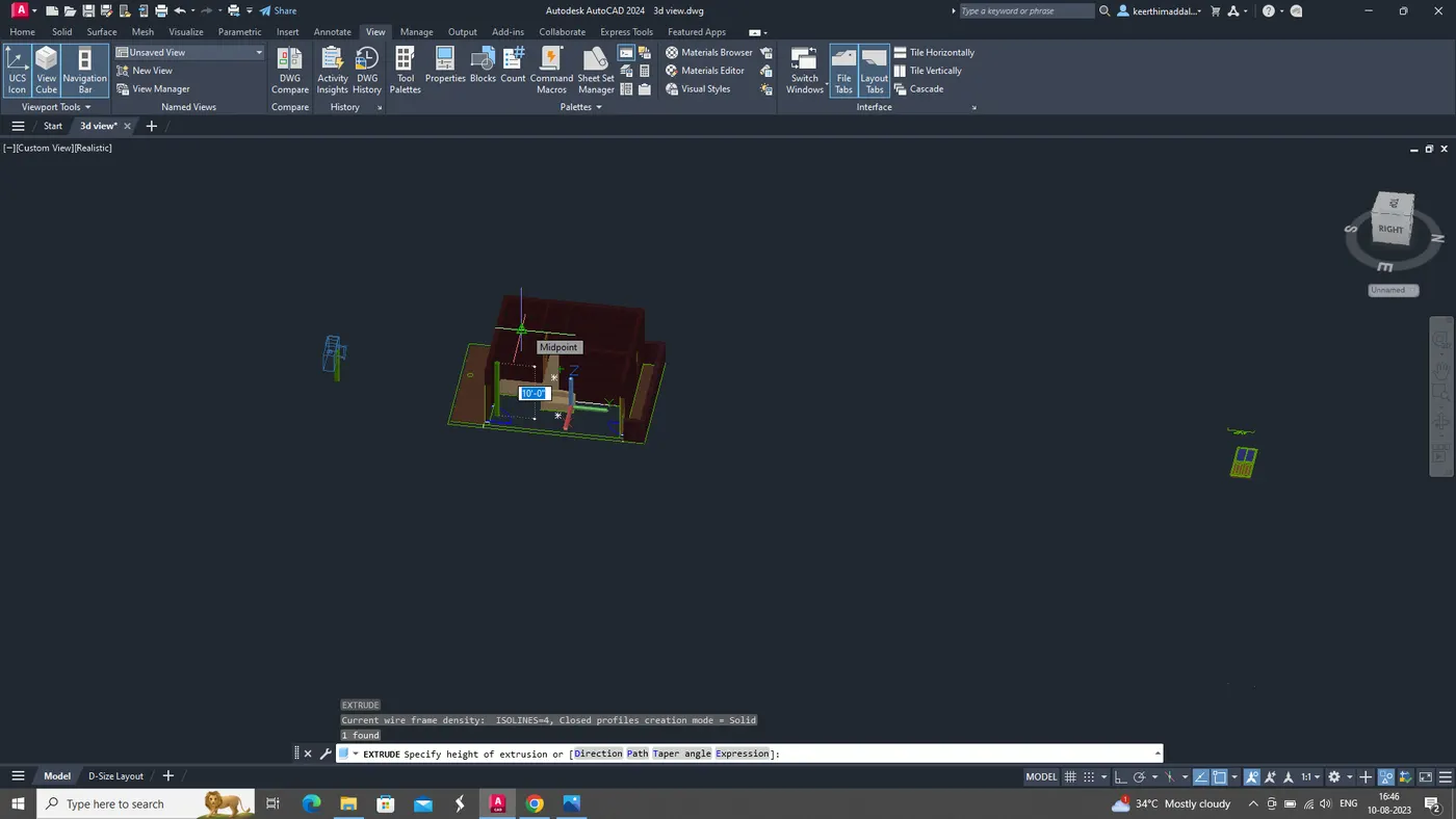
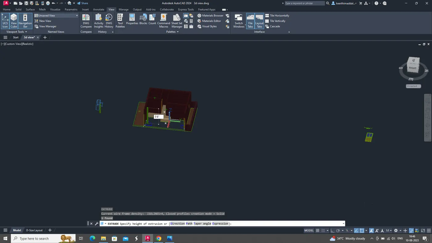
Extrude all wall with adimension of 10'as shown in screen shot below.
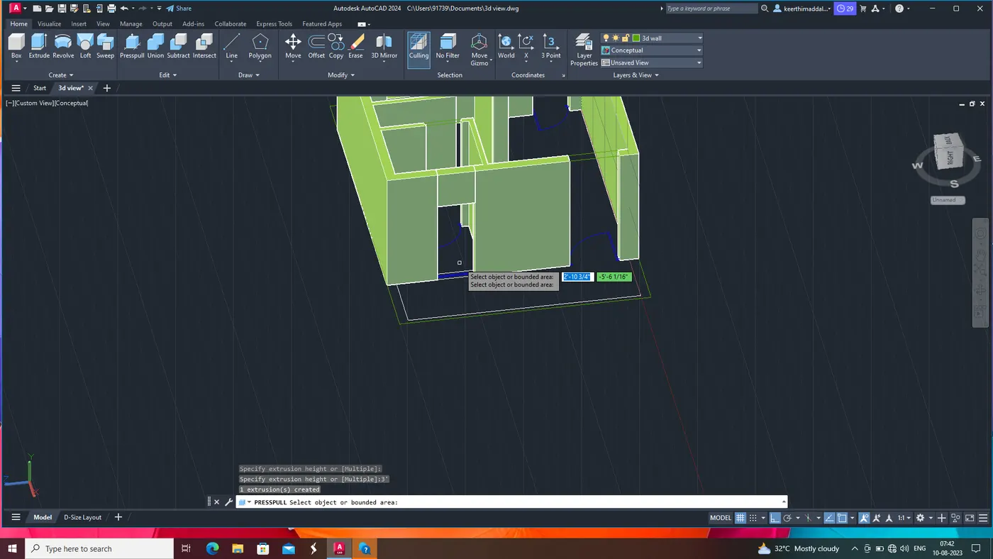
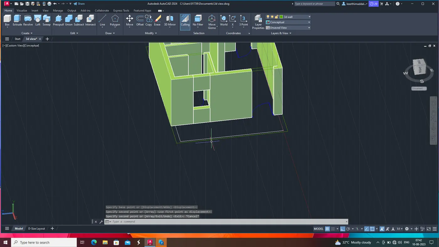
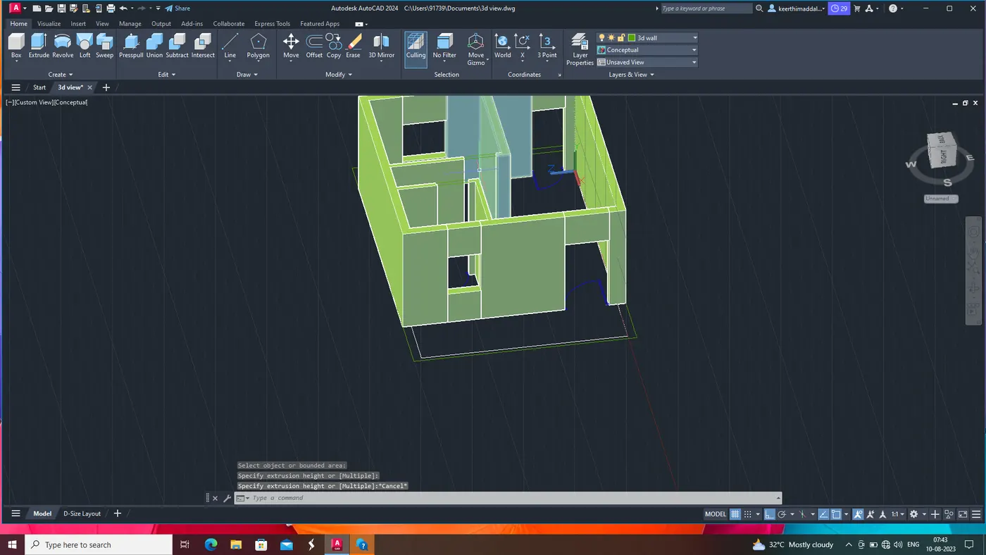
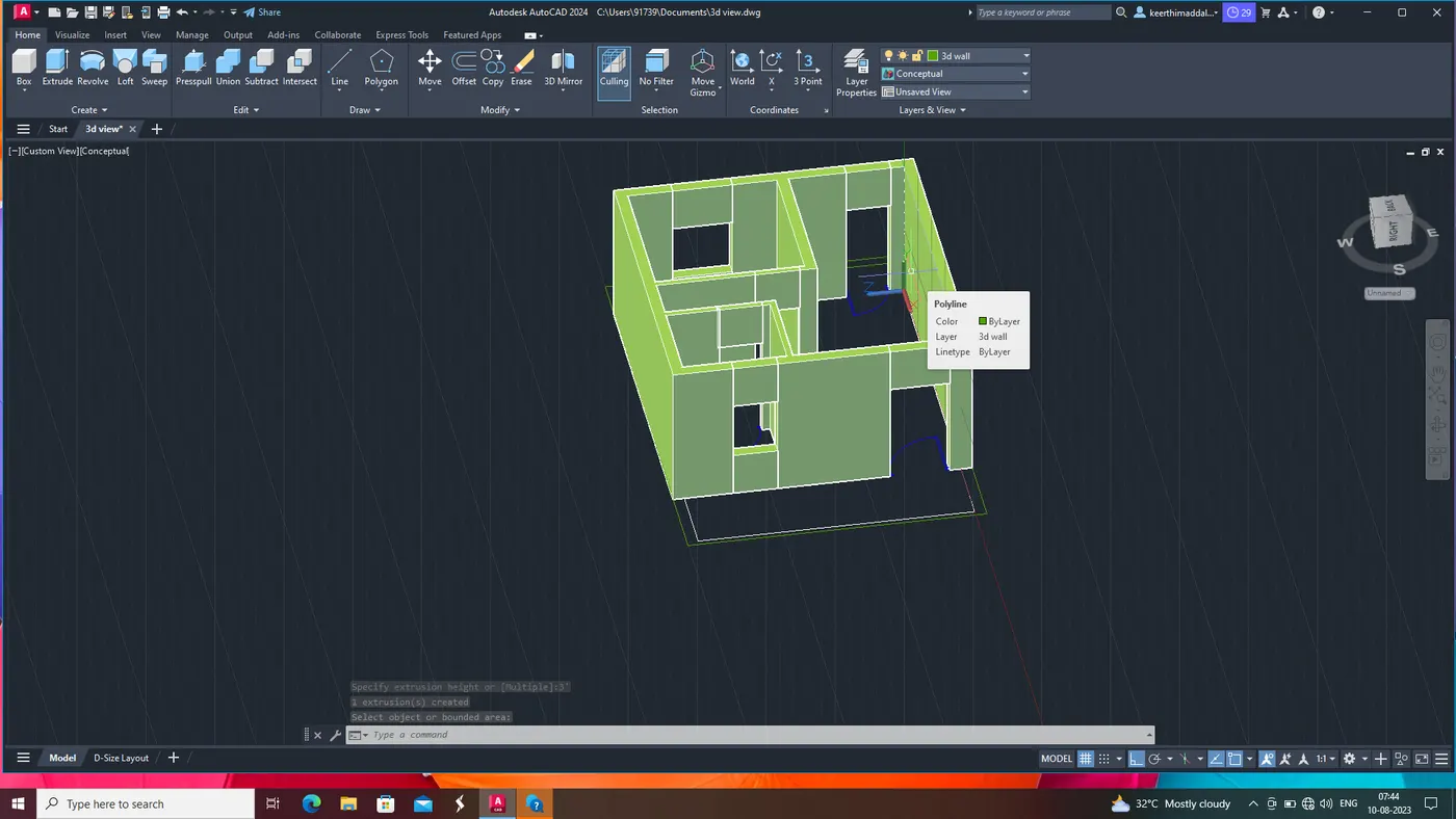
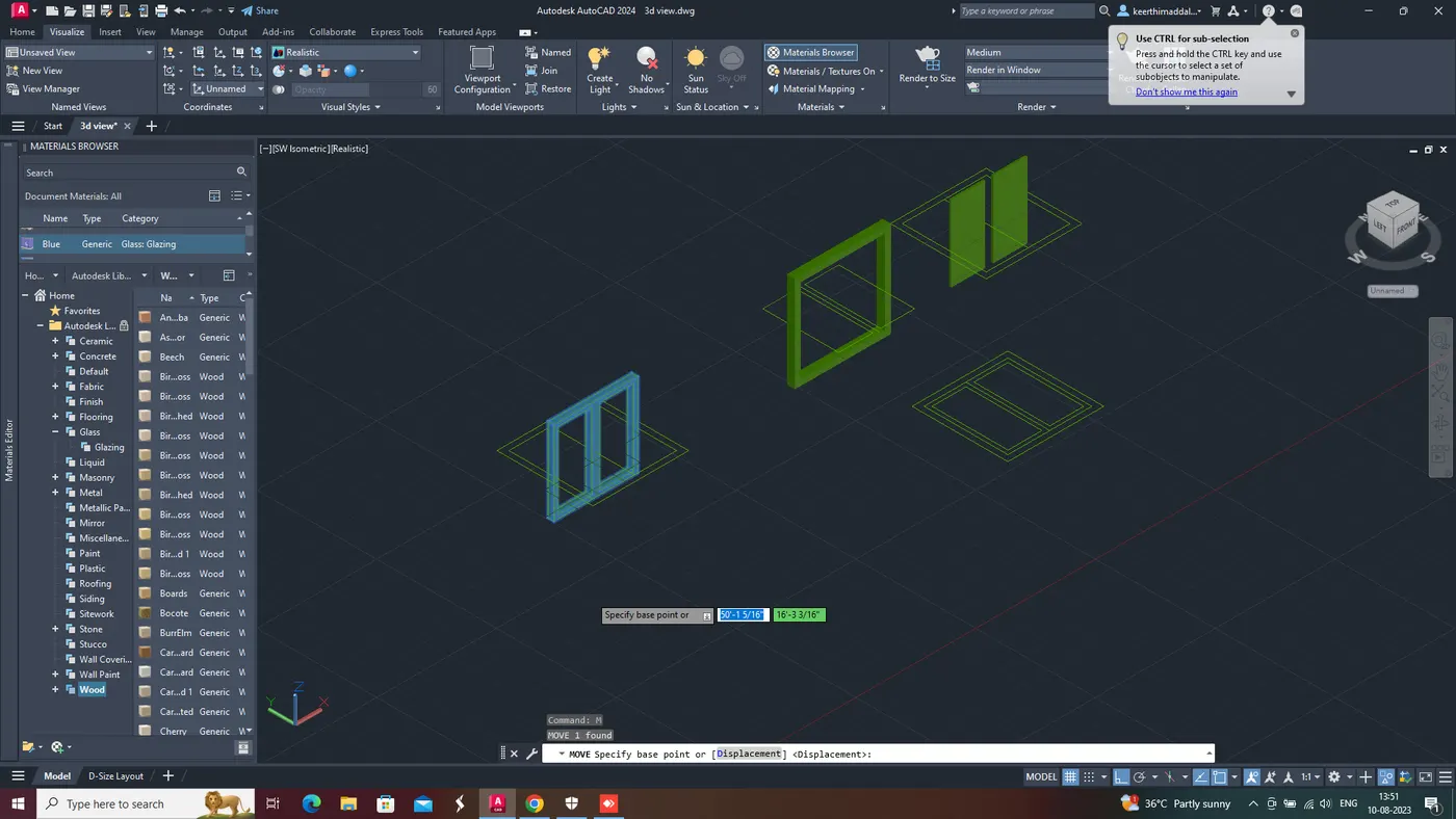
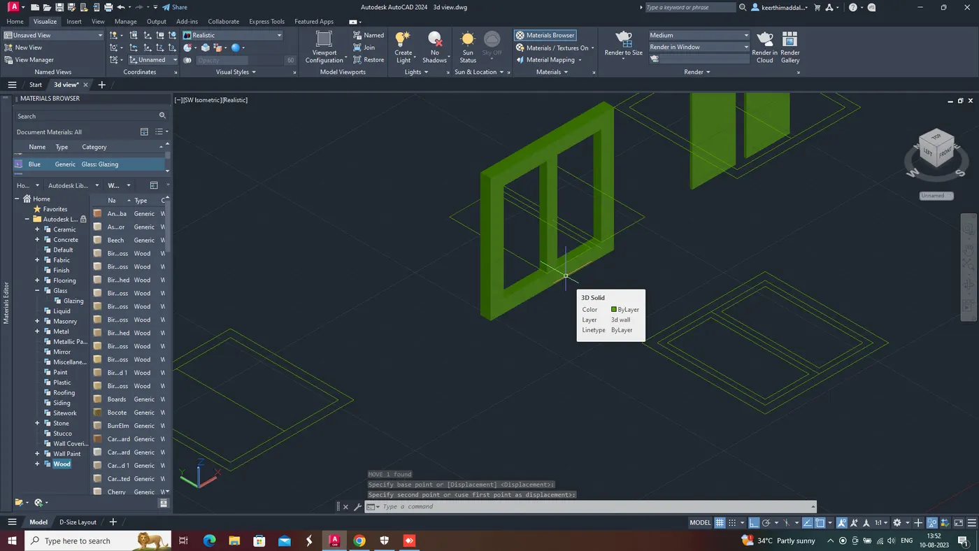
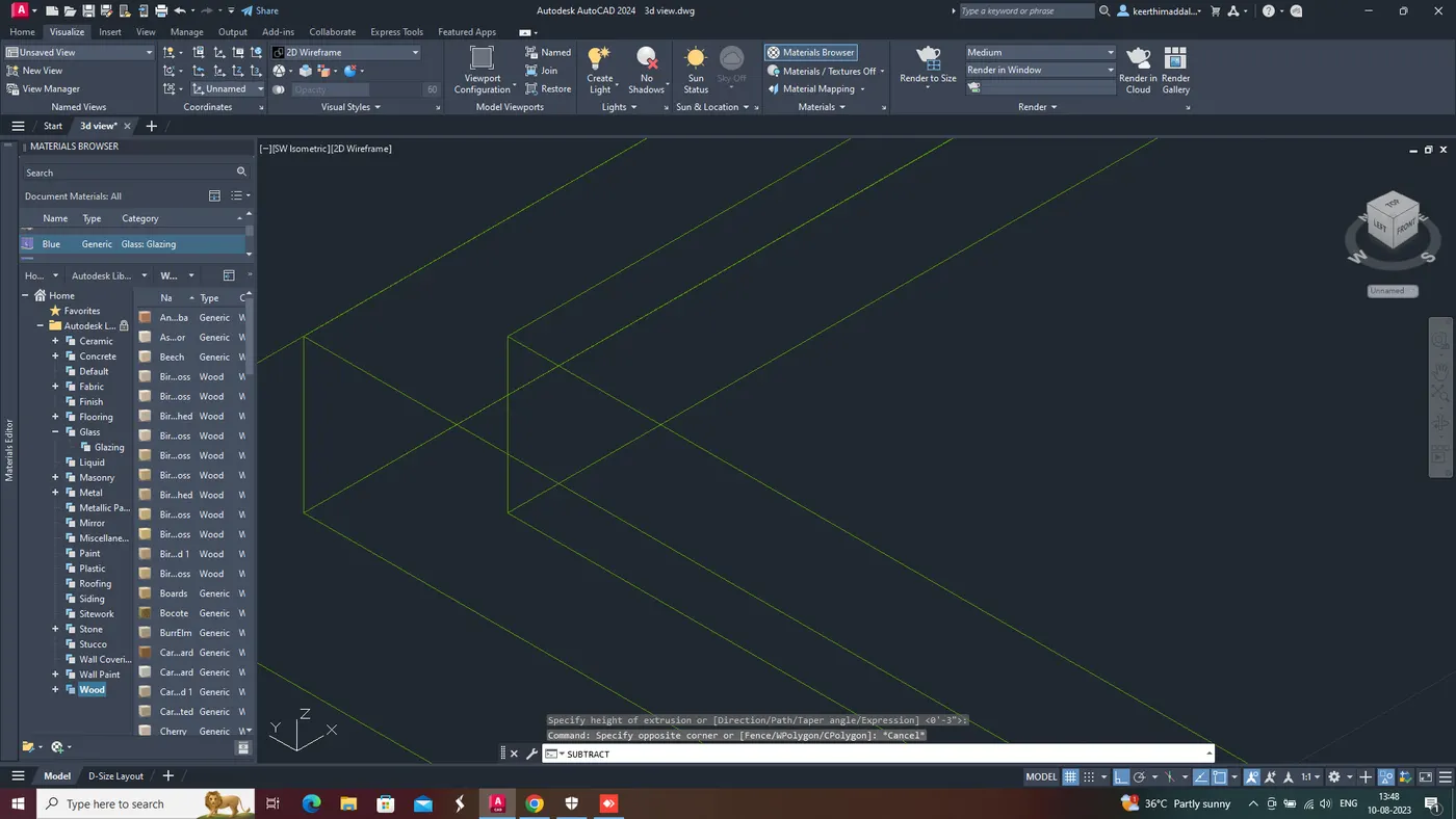
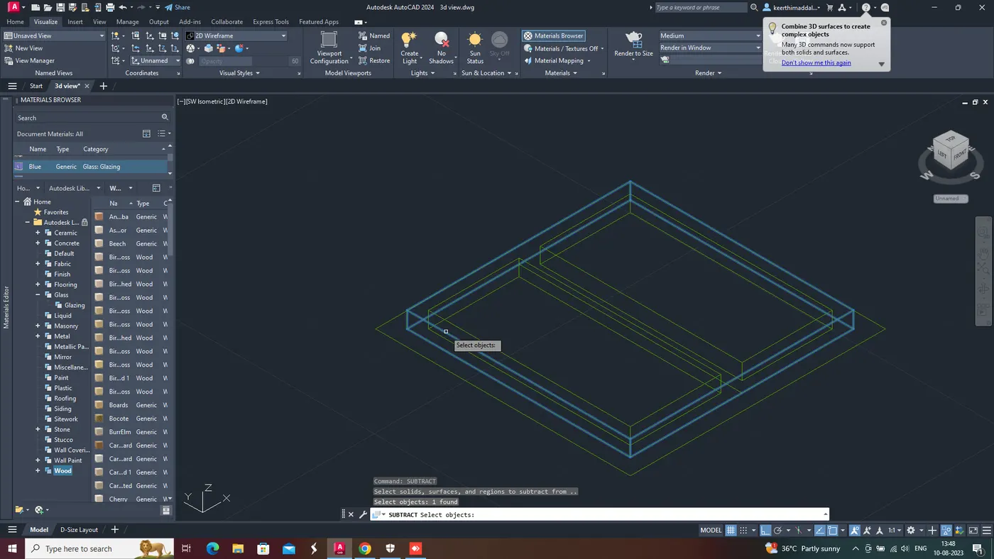
Draw door and window cutoout where you need thenextrude assume sillis 3' extrude the recude the rectangles with 3' and anfrom top for all doors and widows
then copy the same to bottom for windows you need as shown in screen shpt below.
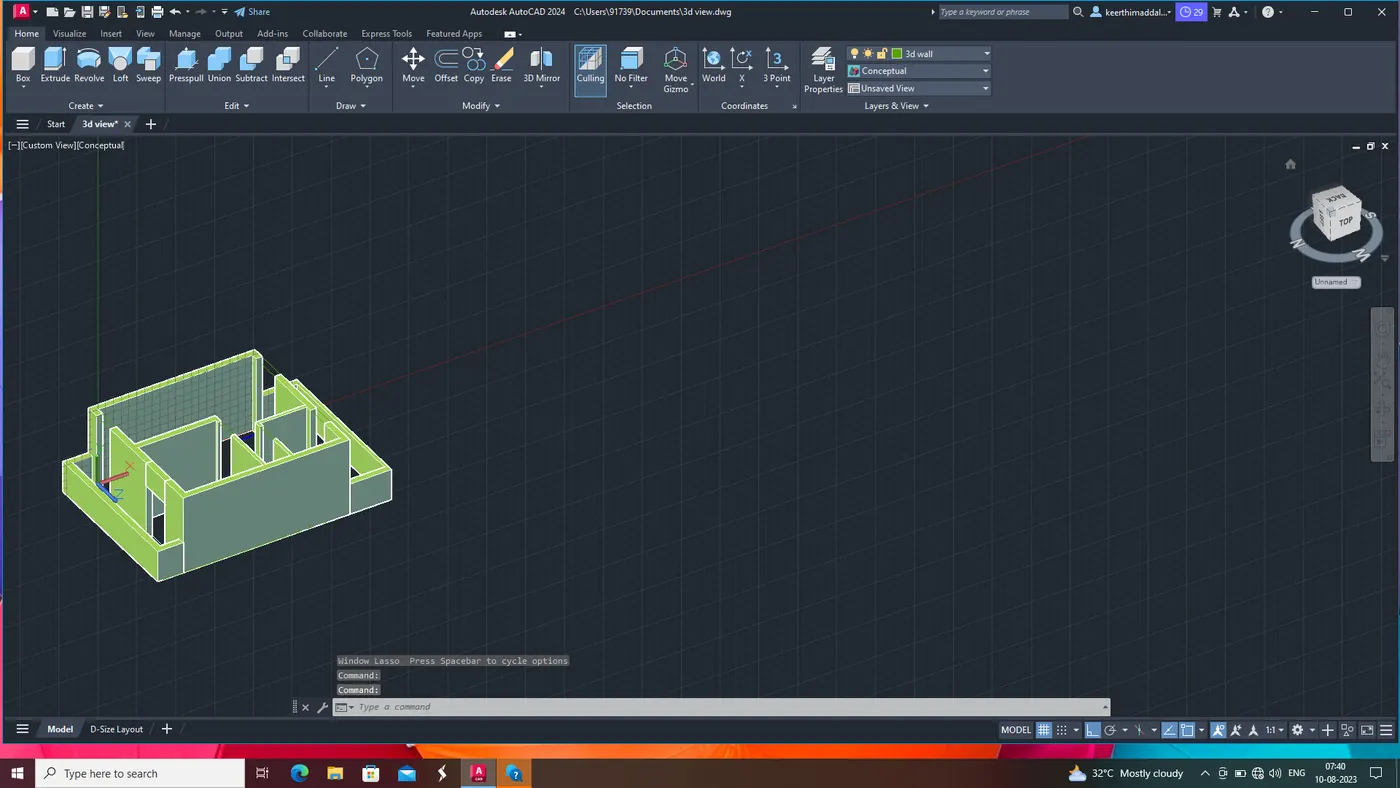
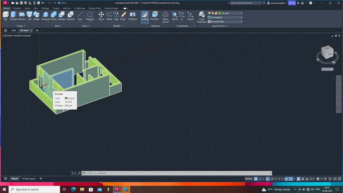
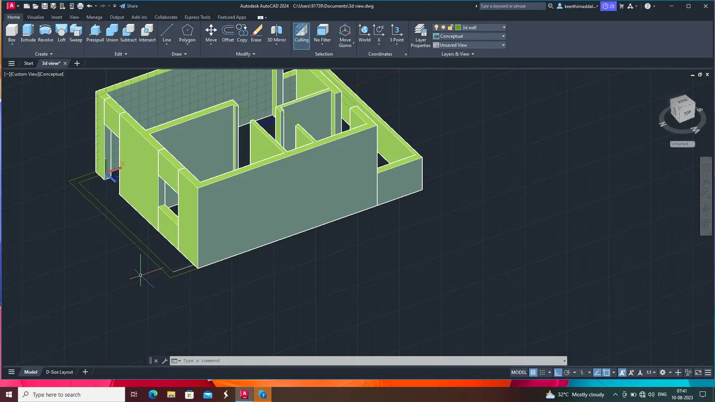
STEP5:
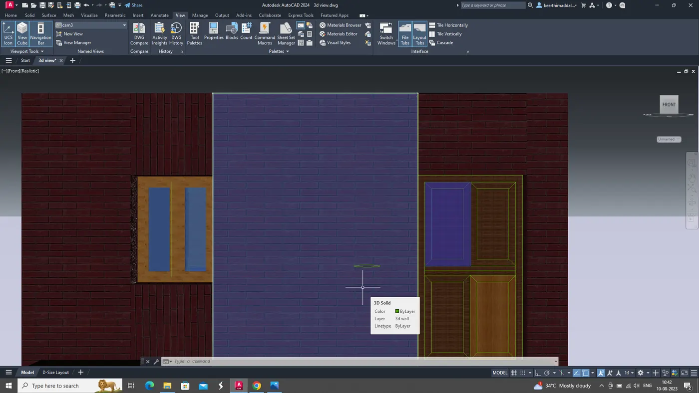
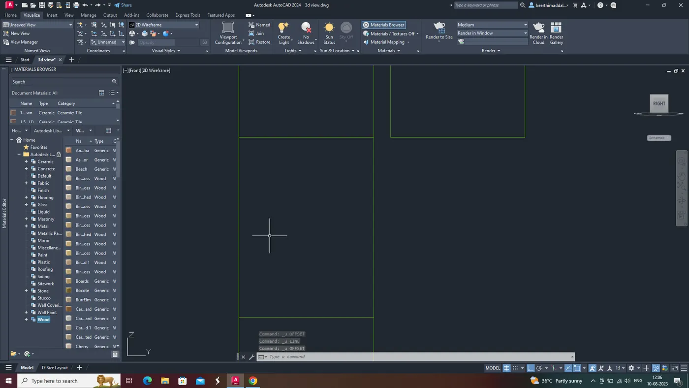
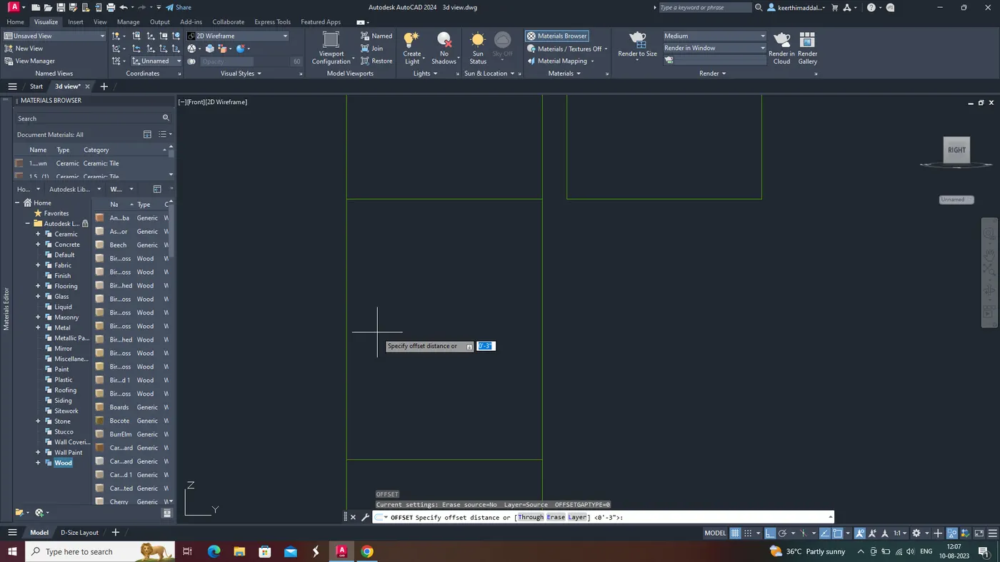
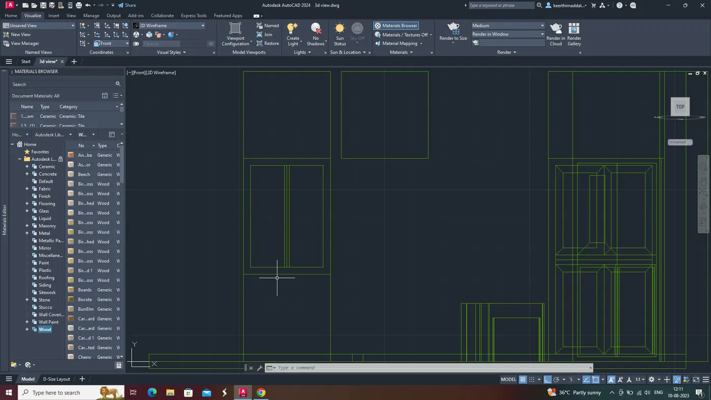
GOTO FRONT VIEW AND DRAW A DOOE ELEVATION USUING RECTANGLE COMMAND 3'X7' THEN DRAW A OFFSET OF 3" THEN DERAW ALINE LINE IN MIDDLE DRAW AOFF OF 2" IN BOTHSIDES THEN DRAW ARECTANGLE FOR PANNELS TOPAND AS SHOWN INSCREEN SHOT BELOW.
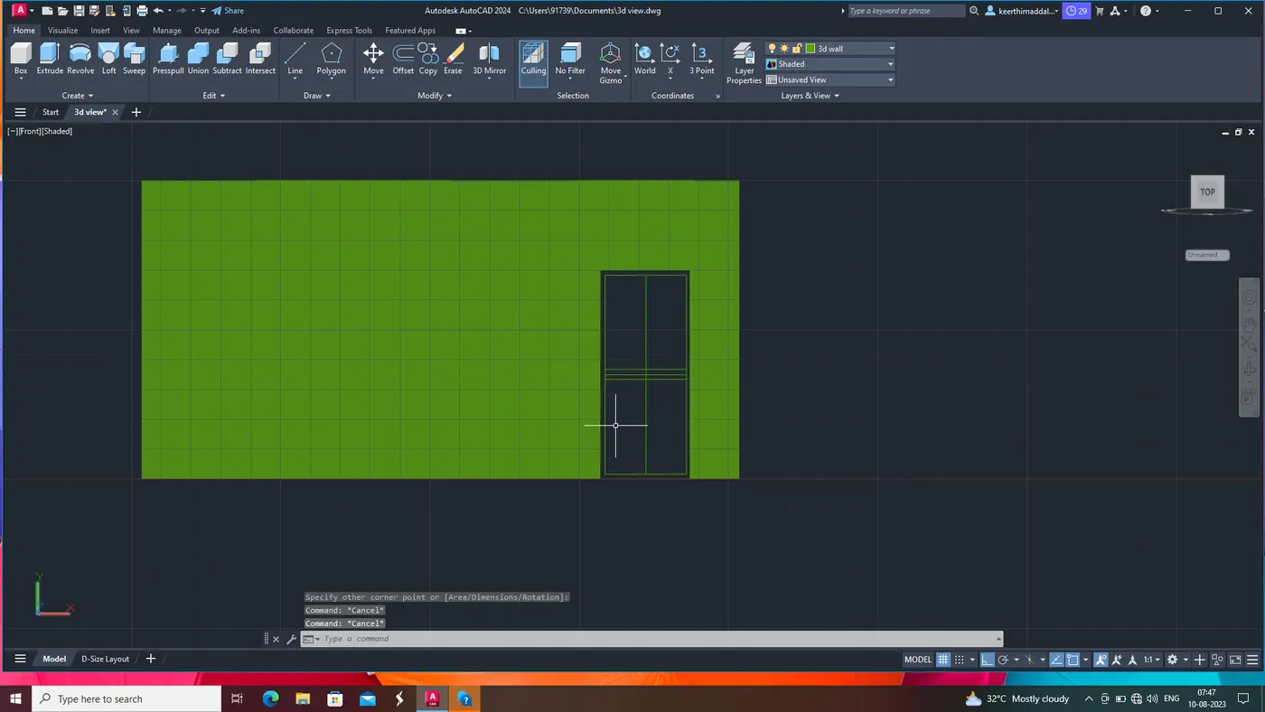
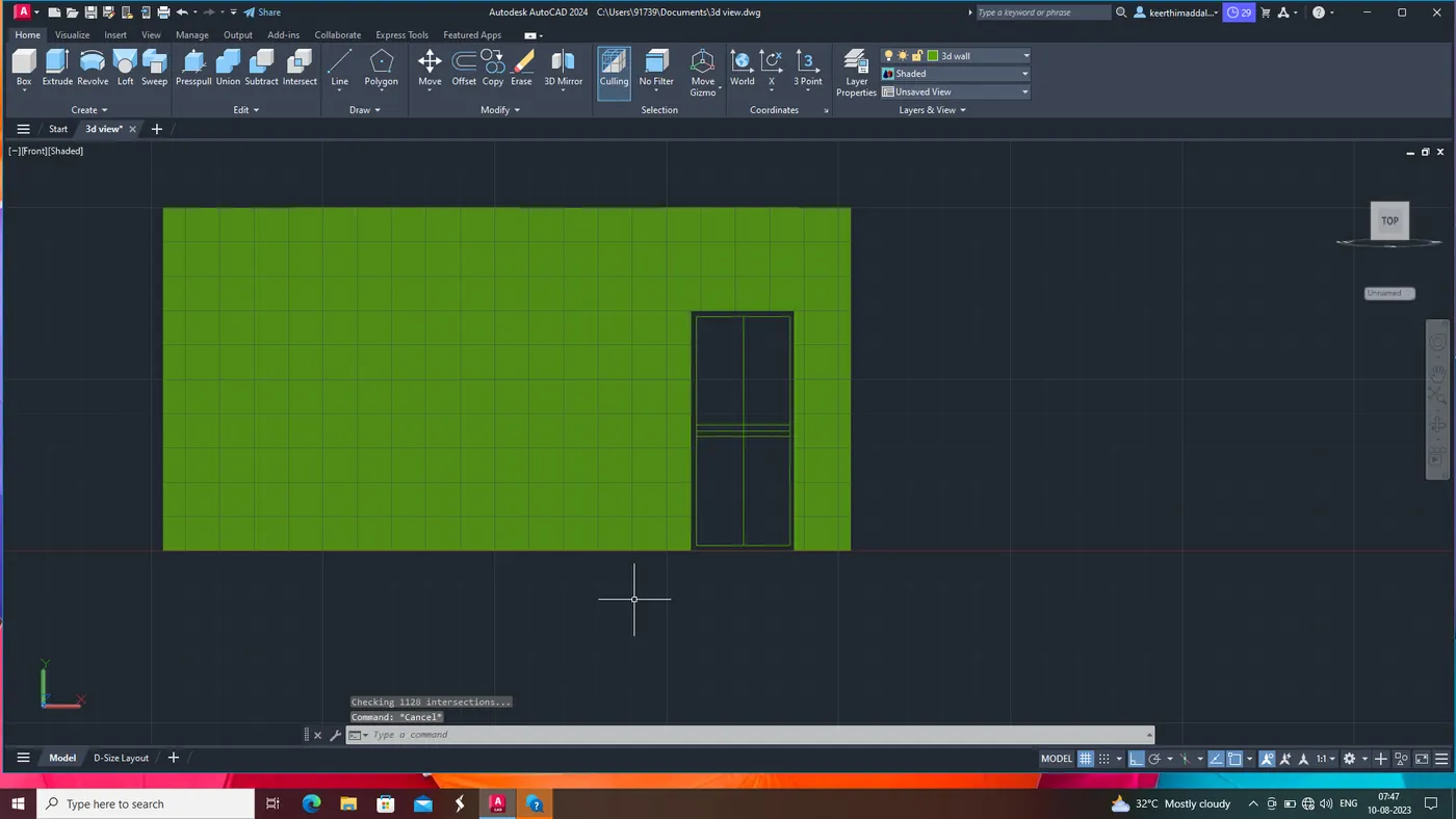
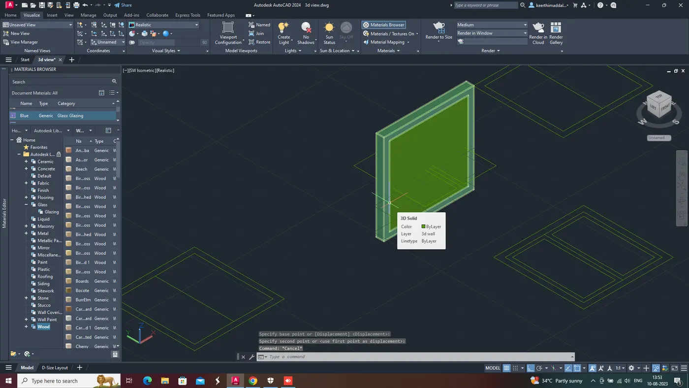
THEN APPLY THE MATERIAL FROM MATERIAL BROWSER AND ASSIGN THE MATERIAL ASSIGNING TOOL. ASSHOWN IN SCREEN SHOT BELOW.
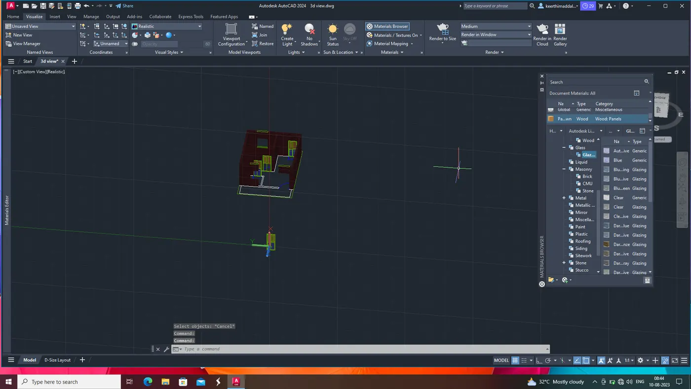
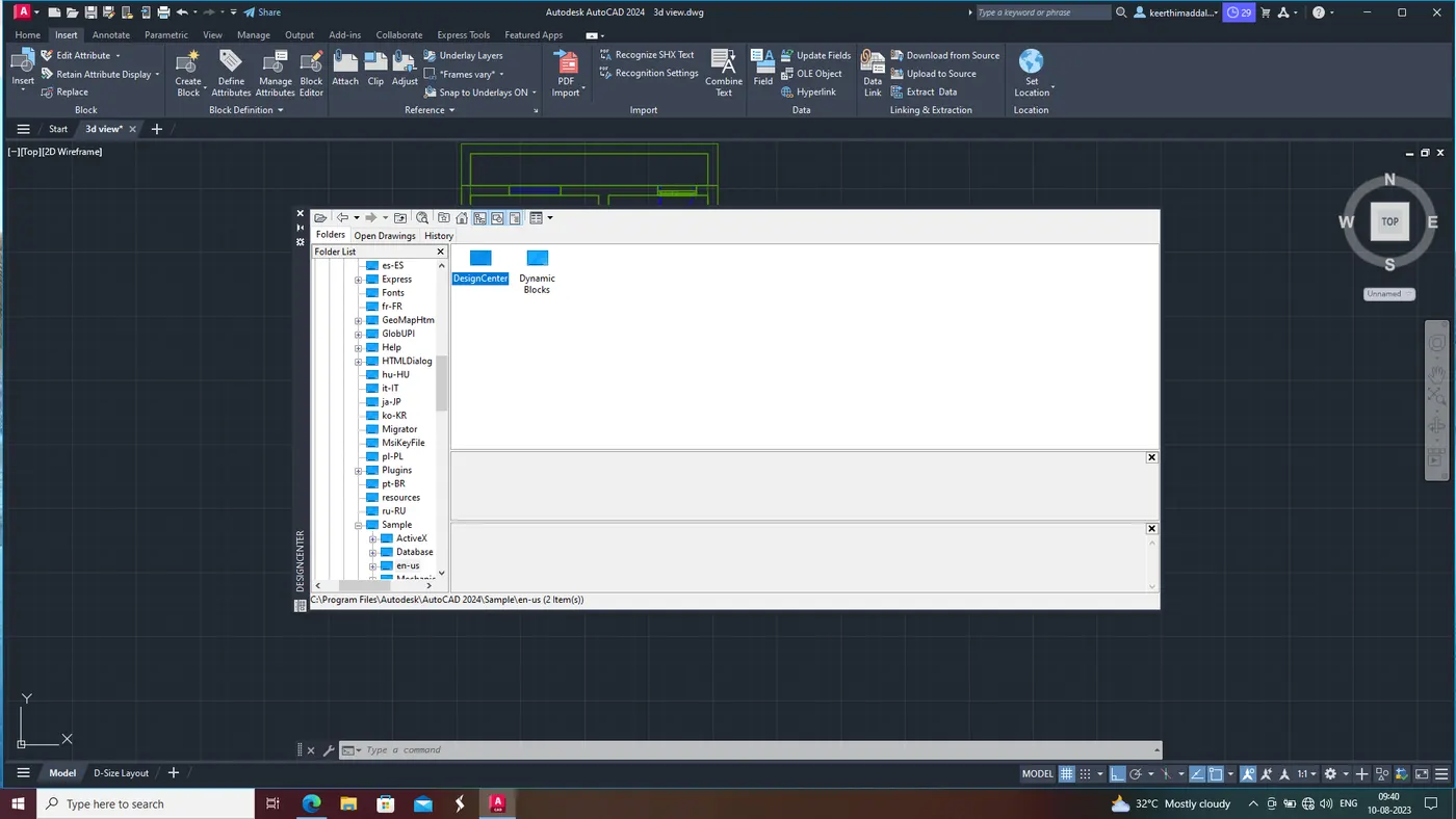
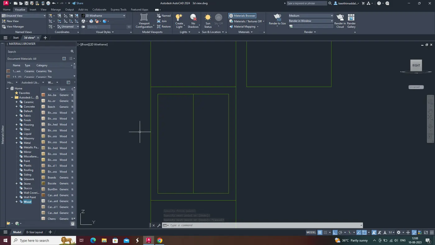
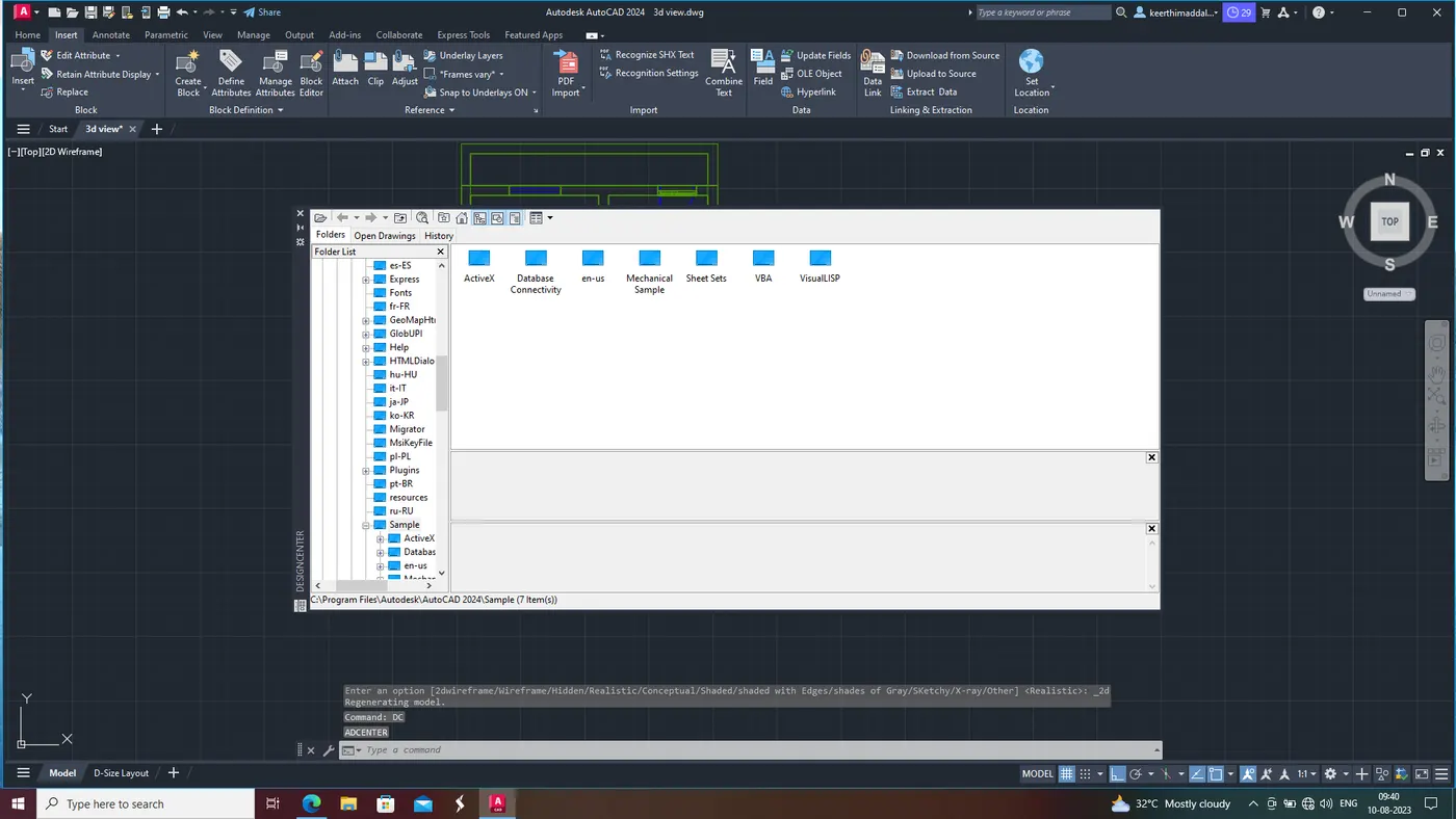
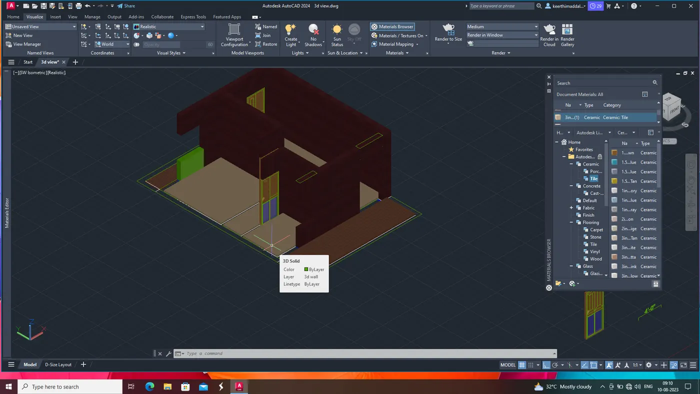
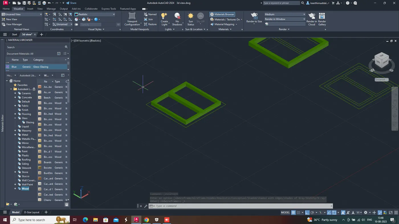
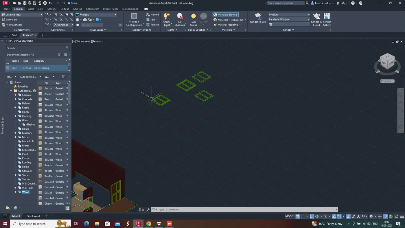
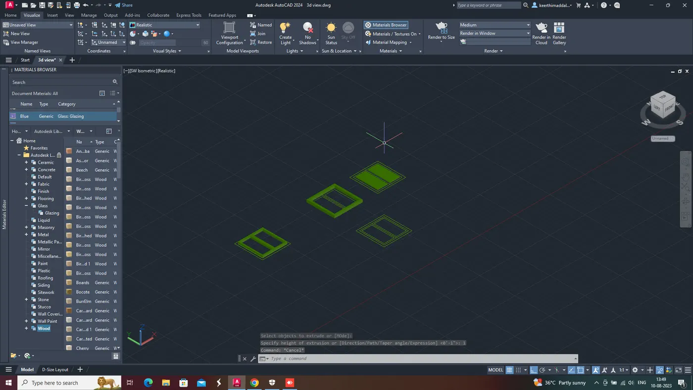
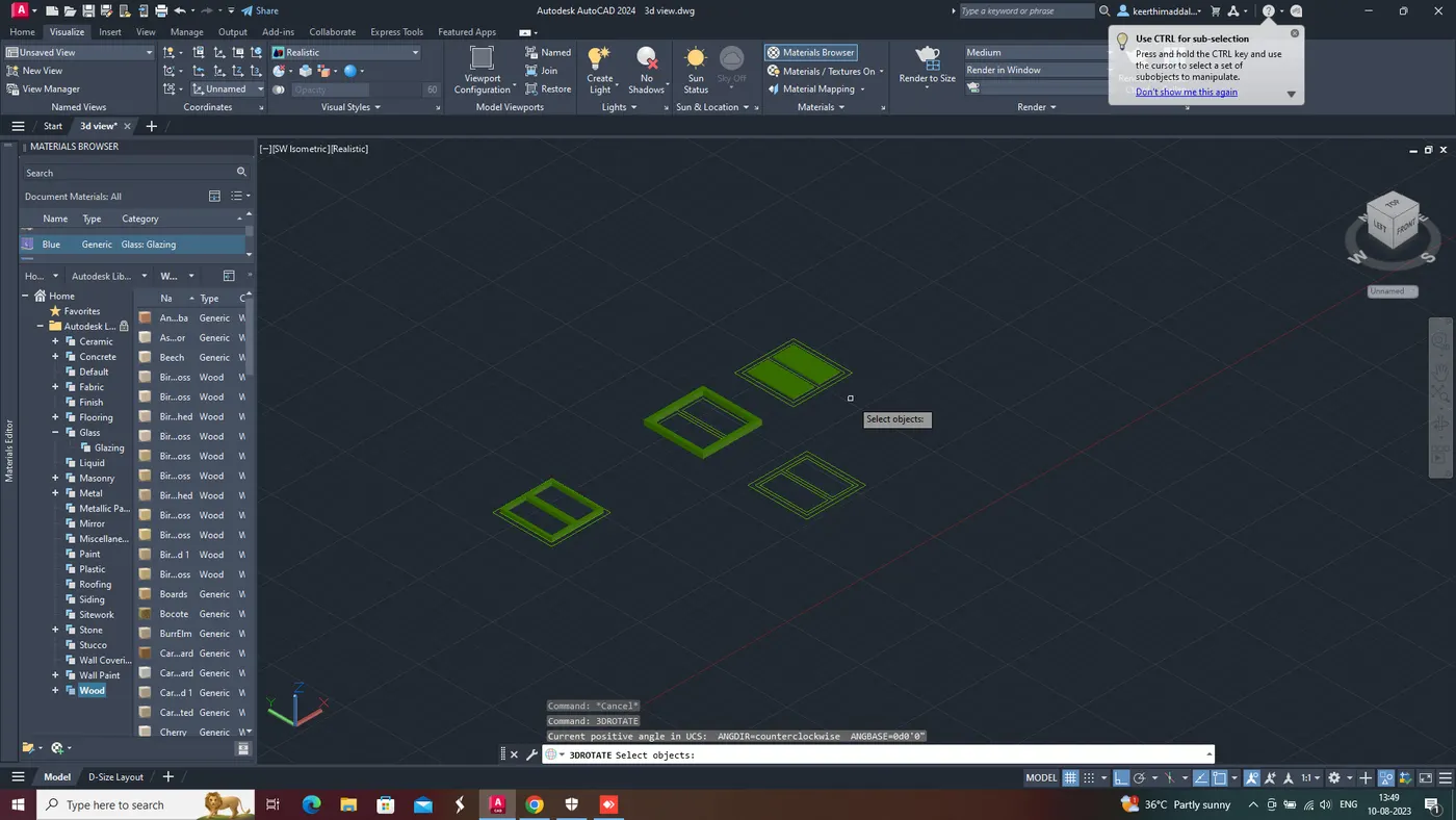
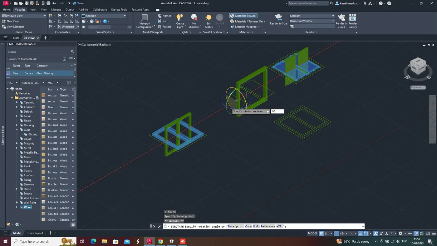
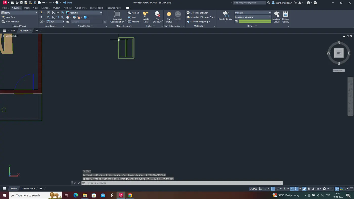
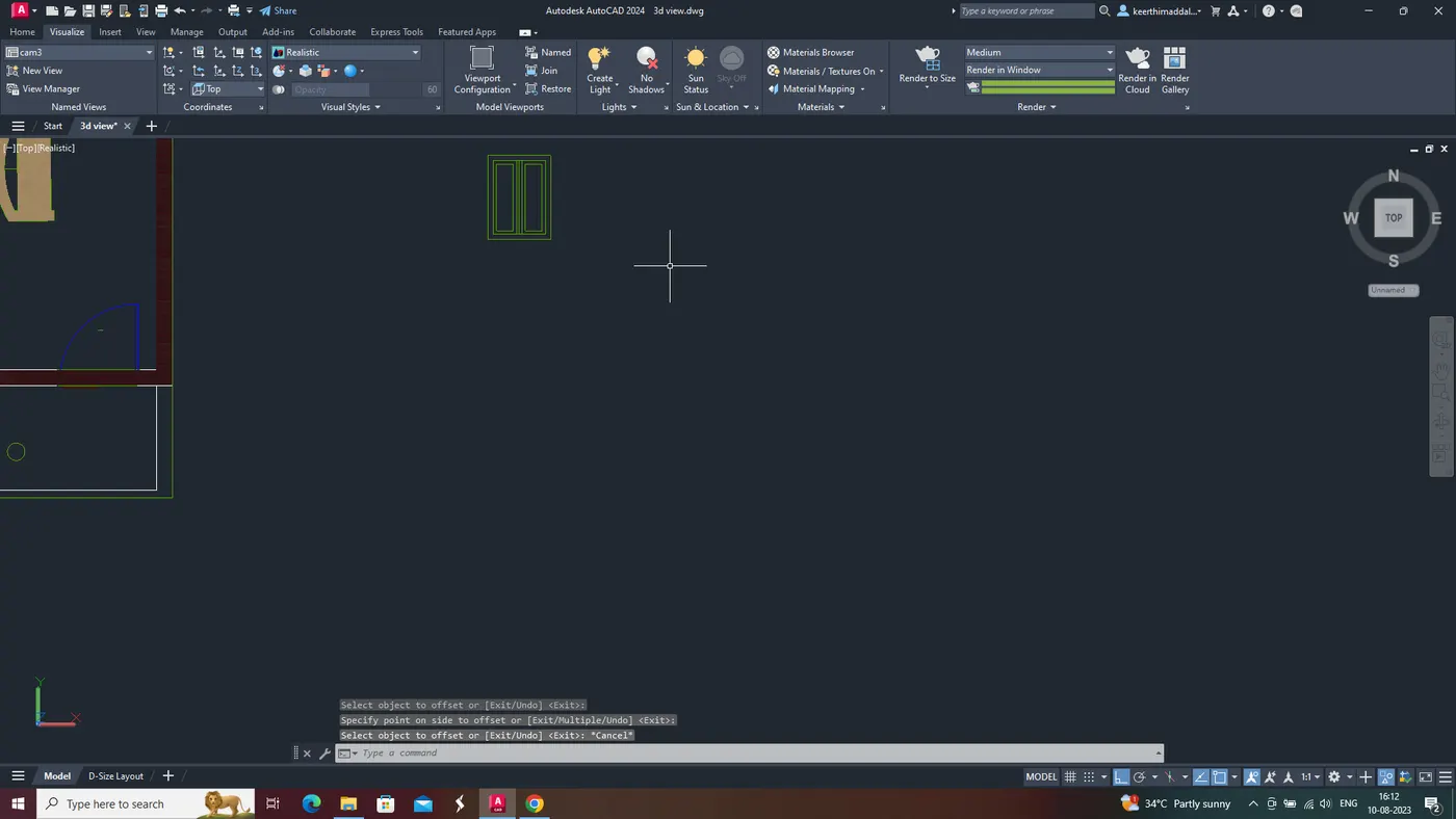
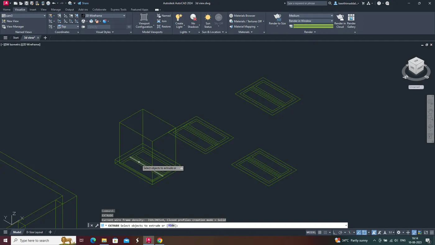
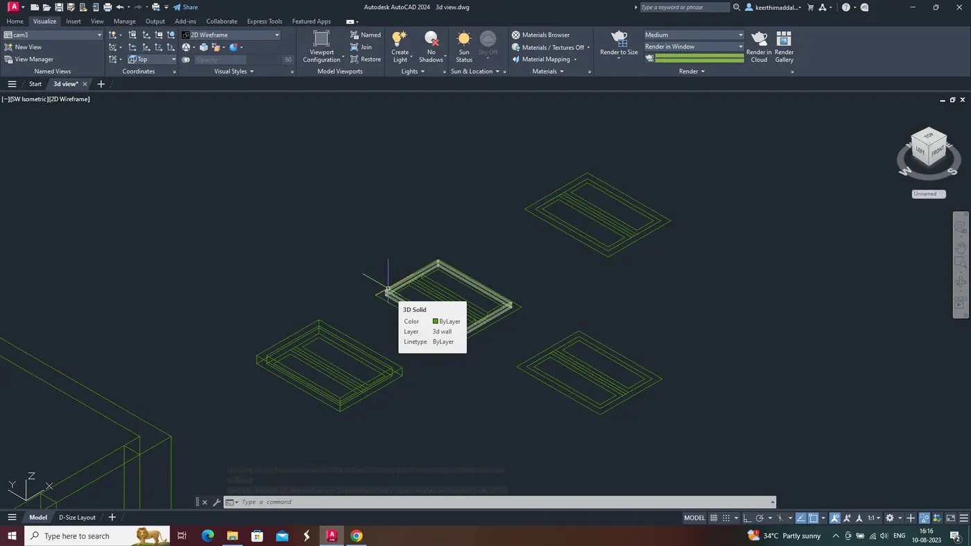
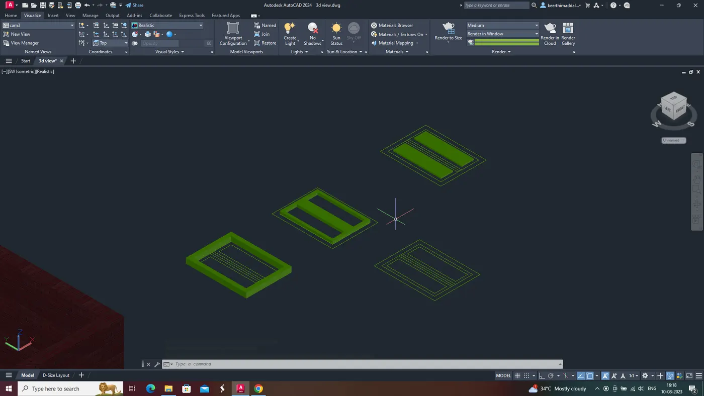
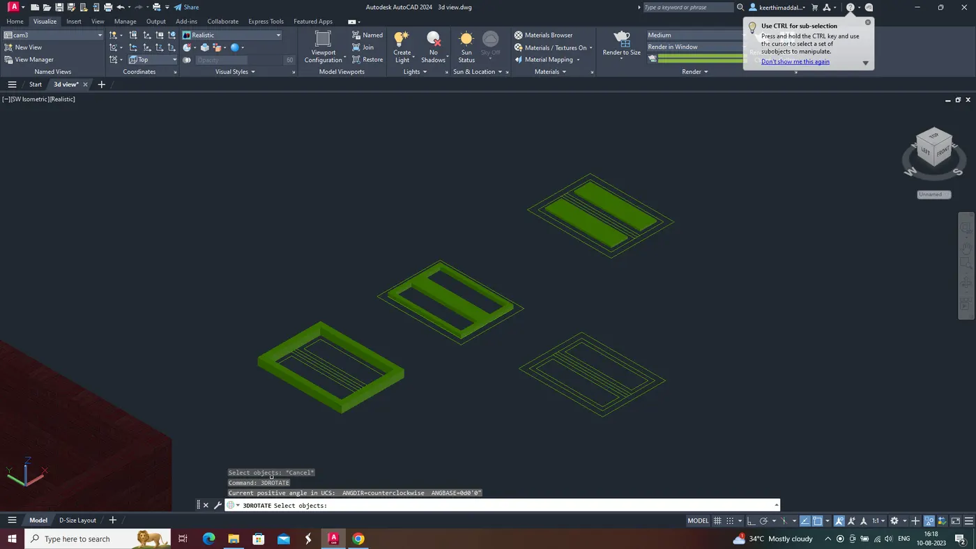
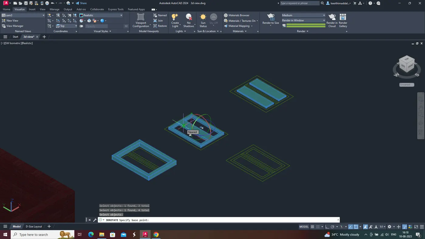
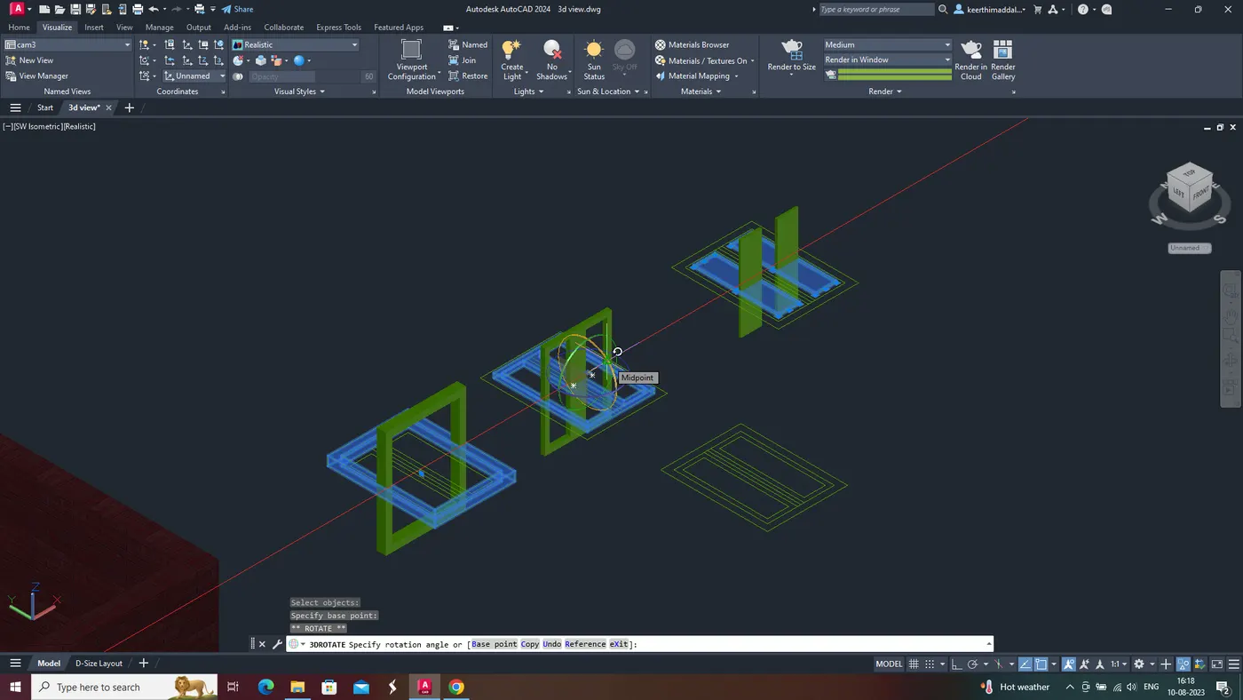
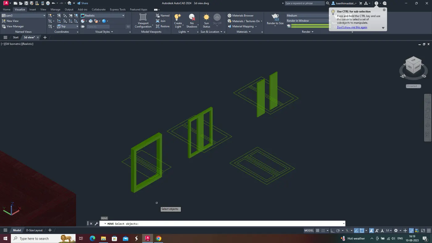
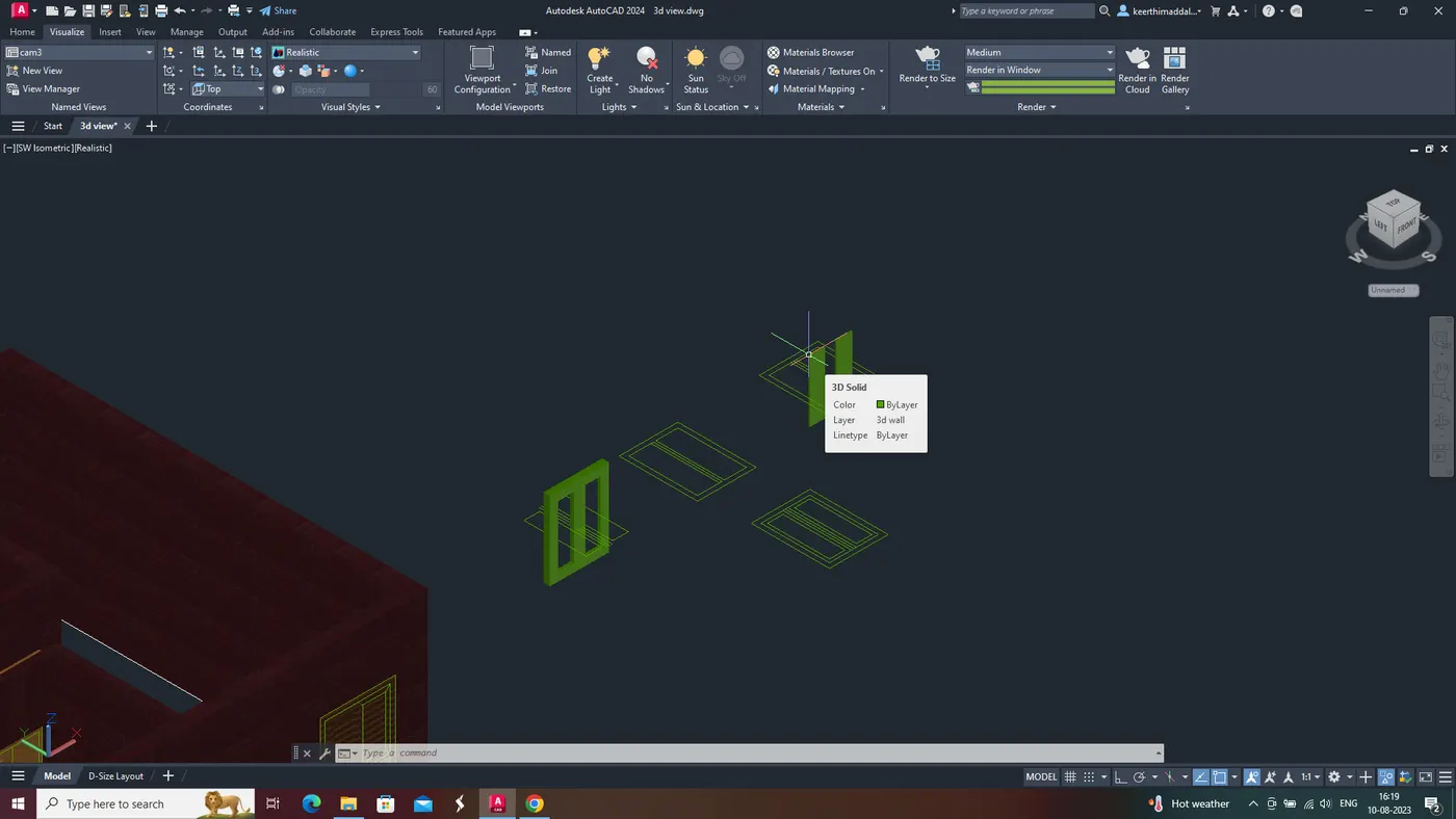
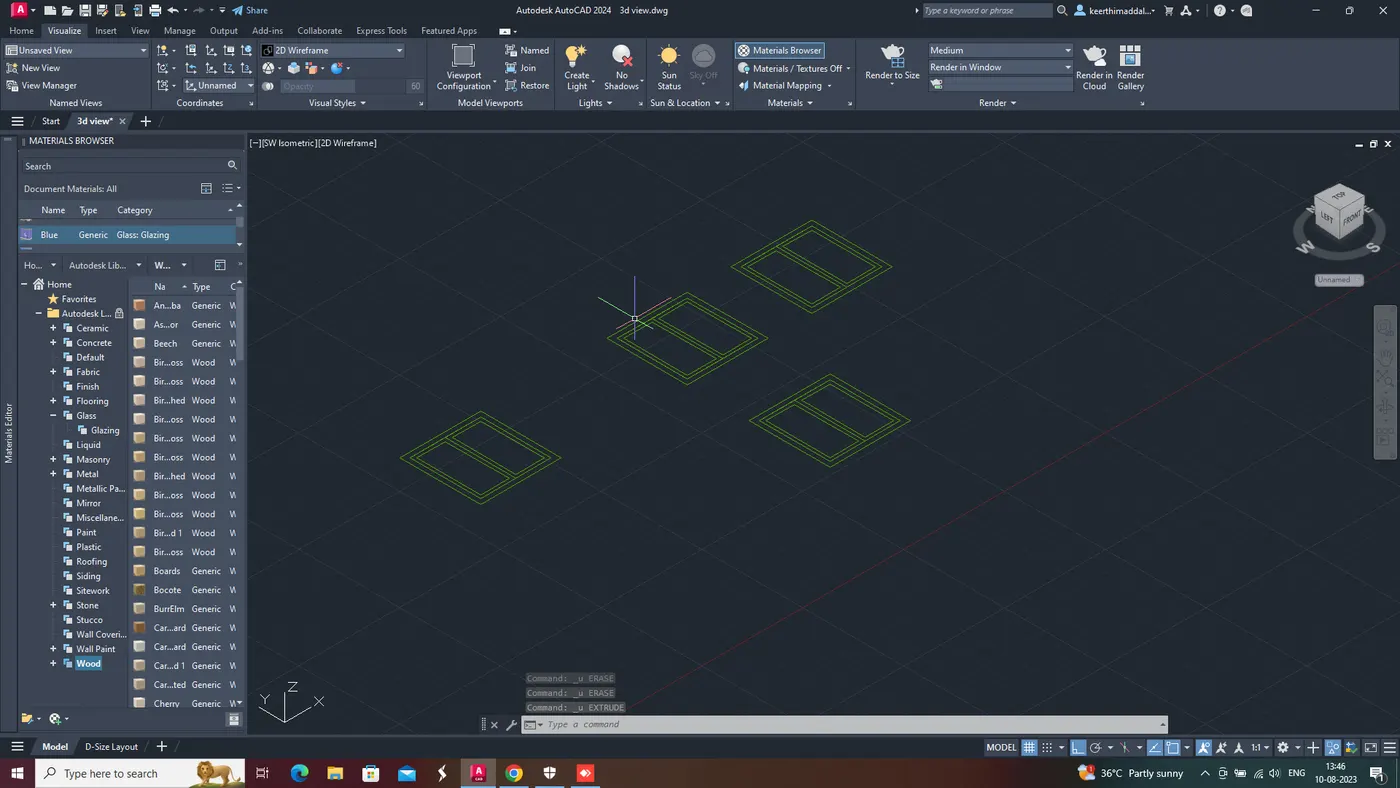
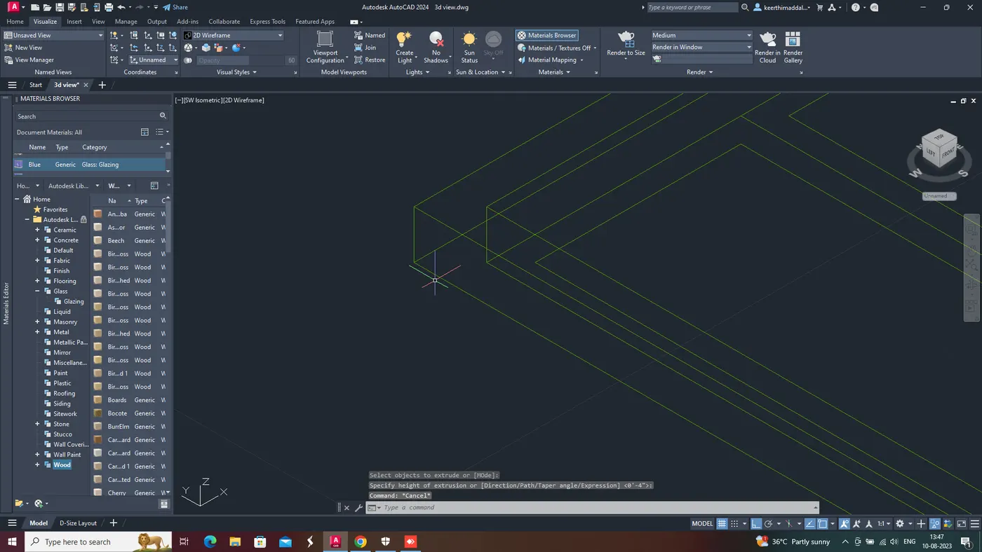
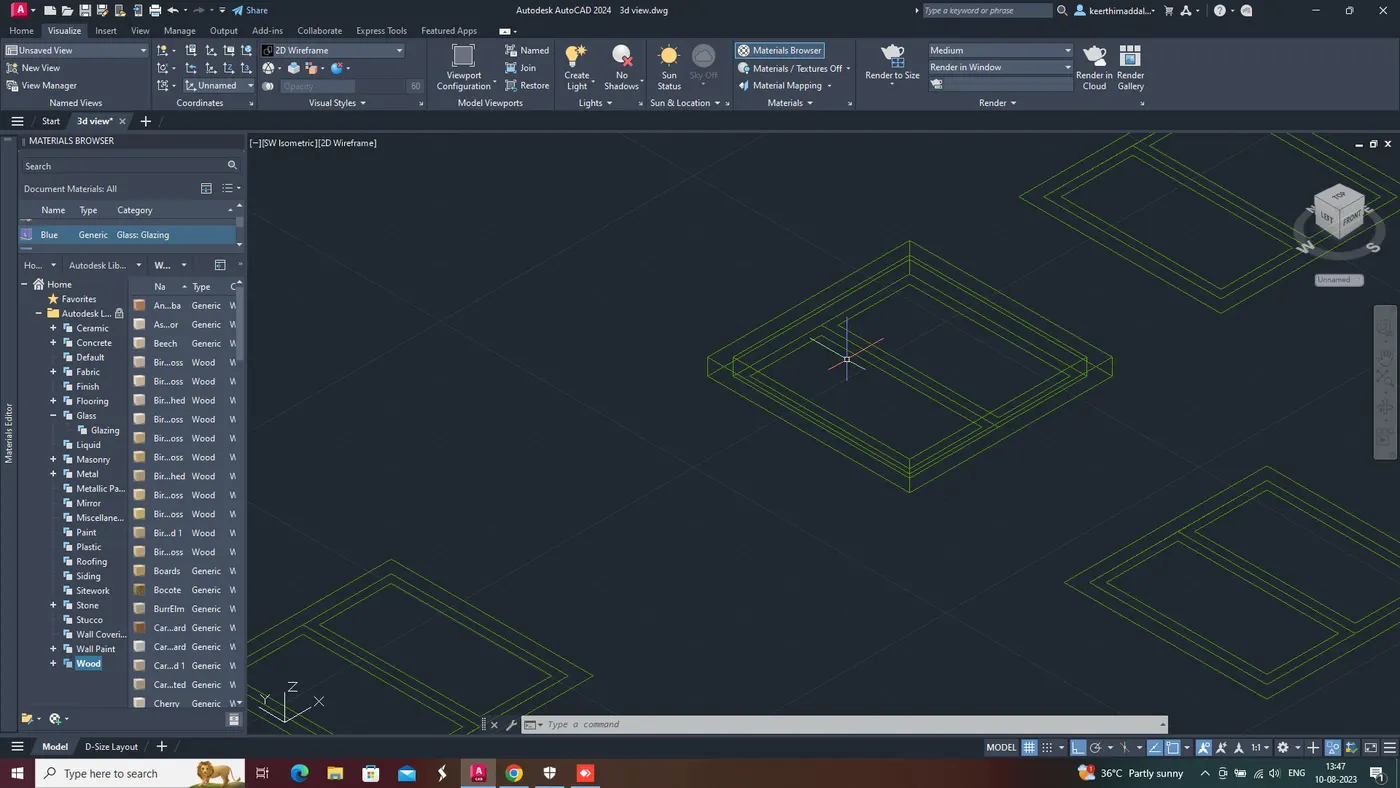
DRAW A WINDOWS AS SHOWIN SCREENSHOT BELOW.
STEP 7
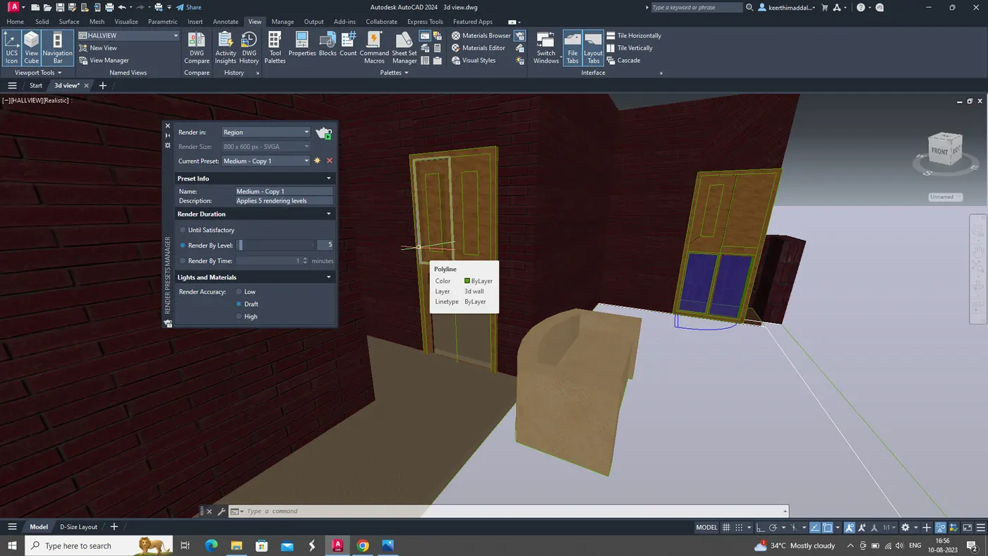
RENDERING