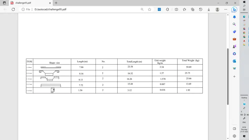
Creating Bar Bending schedule, Different Door types, and Creation of standard drawing templates using AutoCad
1. Create the templates as shown in Figures. Take the size of the title block as per industry standards or you can assume it as per the size of the paper. Use text and attributes wherever required. After creating the title block you need to save it as a block with names: Custom1_titleblock and Custom2_titleblock, respectively.
ANS.
COMMANDS
1.UNITS
2. LIMITS
3.RECTANGLE
4.OFFSET
5.XPLODE
6.ATTRIBUTE
7.BLOCK
8. PLOT
STEP1
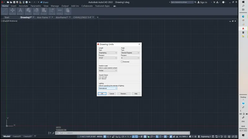
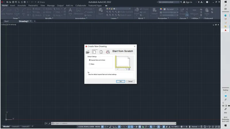
1.Open autocad set units as shown inscreenshots below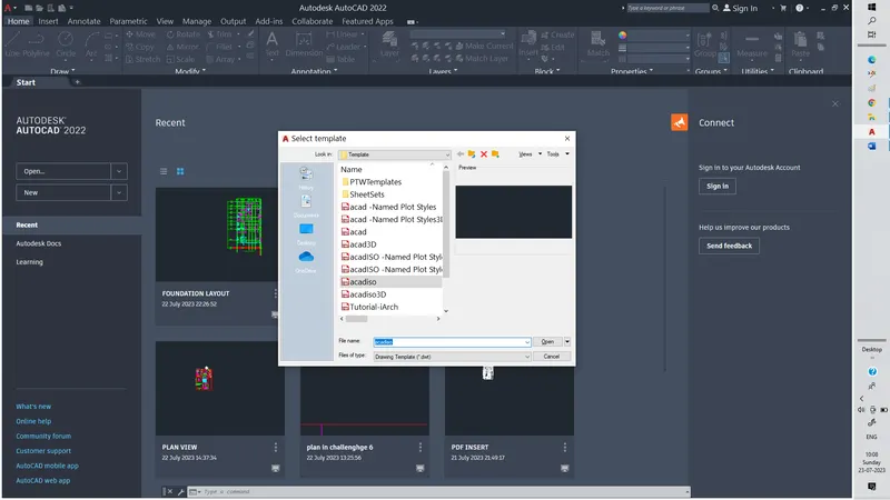
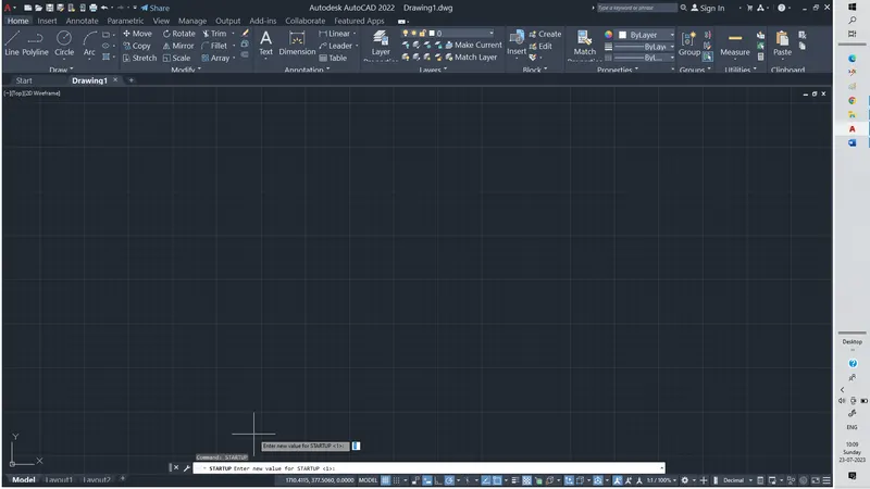
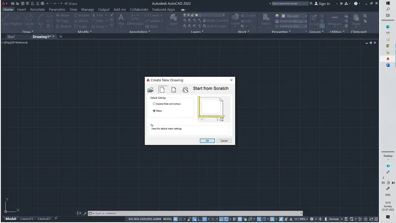
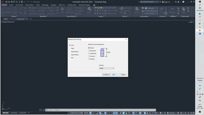
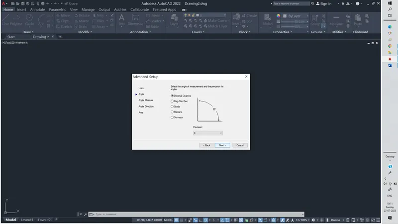
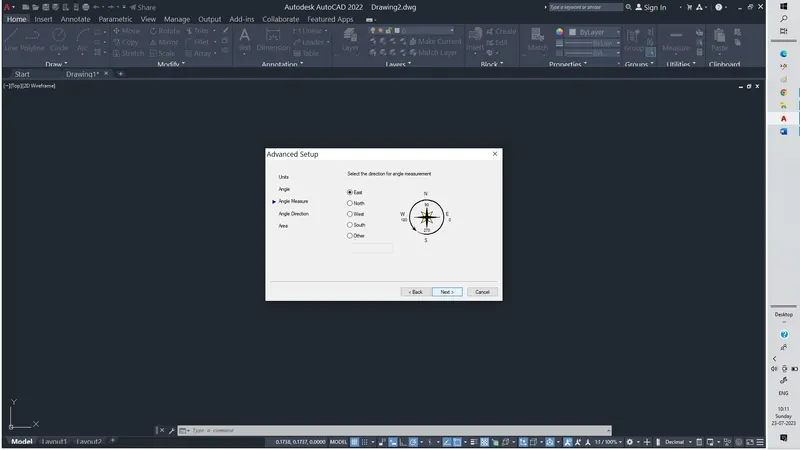
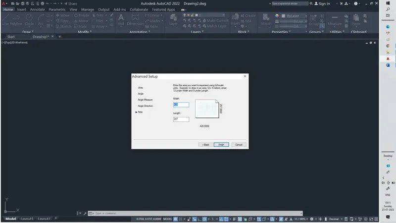
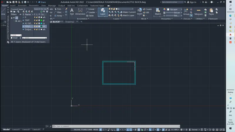
1 Draw a rectangle with dimensions 420 x297 mm and drraw an offsetof 10mm tothe rectangle as shown in screen shot below.
Draw arectangle of 50mmx 277 mm and xplode the rectangle.
Draw offset of 10mm, 15mm,10mm.20, 20,40,20,20,20,10,10 in vertical direction.as.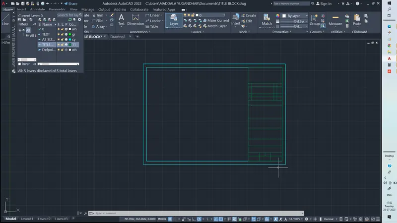 shown inscreen shot.
Using attribute palce the text in title block.as shown screen shot.
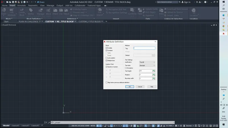
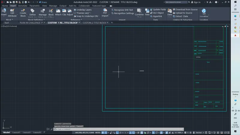
1. Create a block as shown in screen for editing attributes as shown in screen shots.
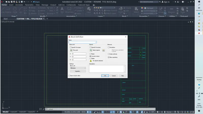
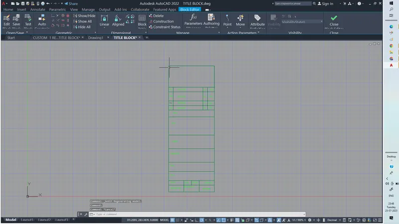
Final output"
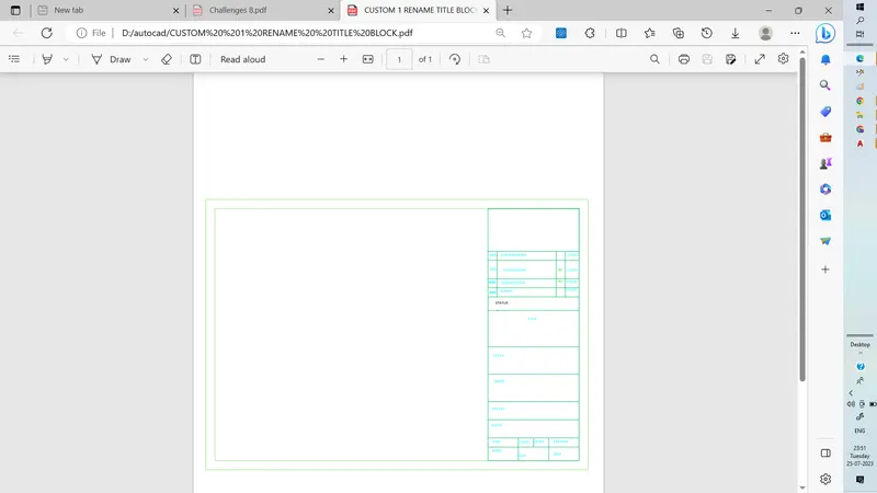
2nd title block
similarly all commands are as like above drawing as shown in screen shots
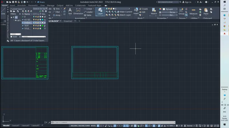
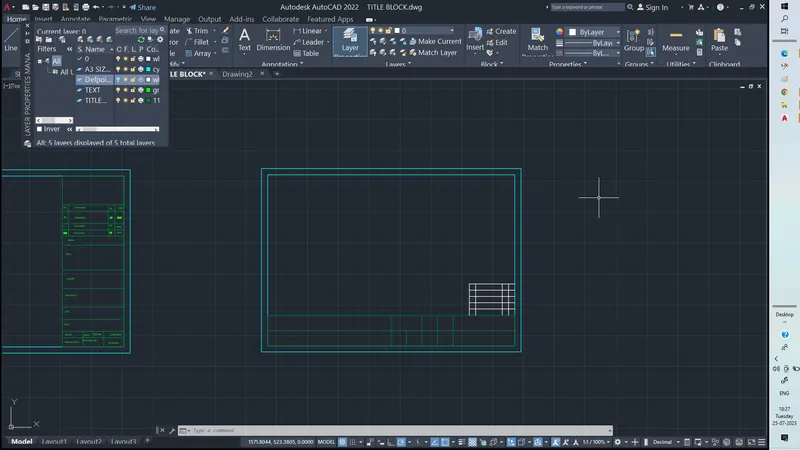
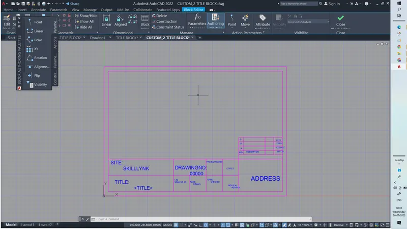
Final output:
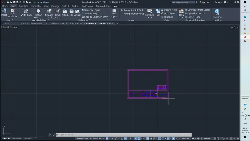 Result:
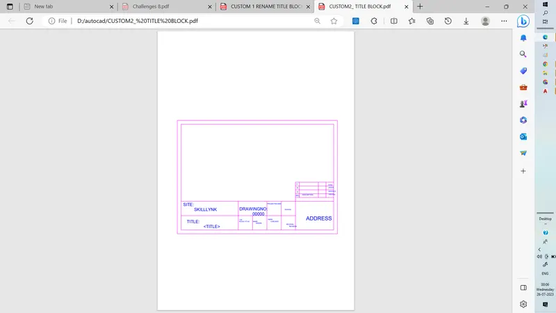
3.ANS.
COMMANDS
1.UNITS
2. LIMITS
3.RECTANGLE
4.OFFSET
5.XPLODE
6.ATTRIBUTE
7.BLOCK
8. PLOT
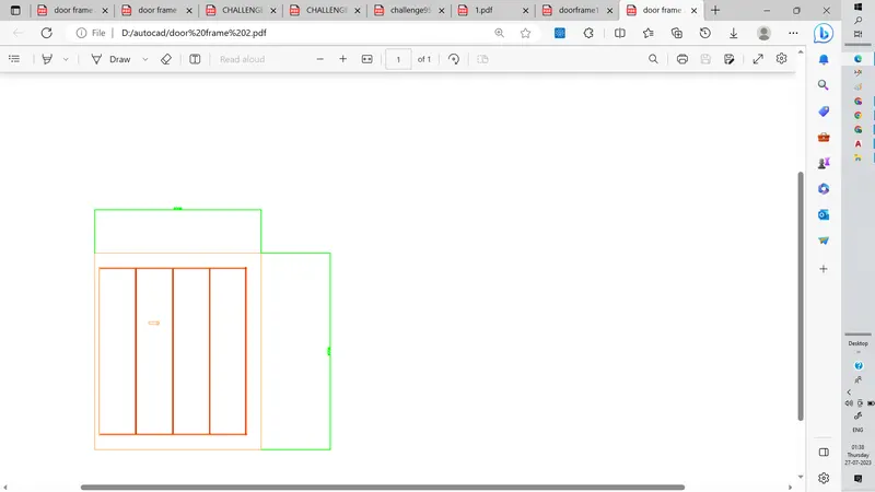
Draw a rectangle of 23030 x 2750 and xplode.
Draw an offset of 200 from top bottom ,right and 60 from left as shown in screen shot below
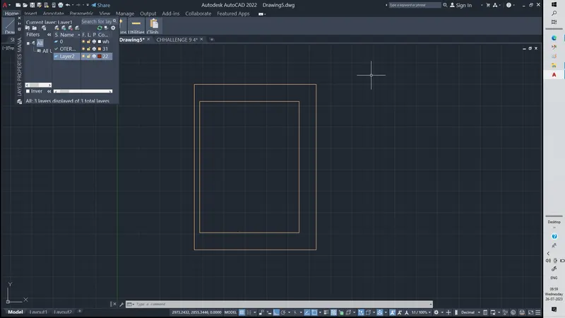
Draw an offset of 15 mm from right ,top, left.
Then divinde horizontal line in to 3 segments and vertical line in to 4 segments.
Using line command draw a point connect to other end as shown screenshot below.
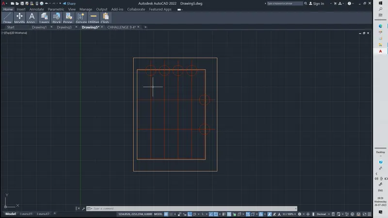
Draw offset of 5mm on bothside of a line in vertical and 75mm both sides on horizontal.as shown in screen shot below.
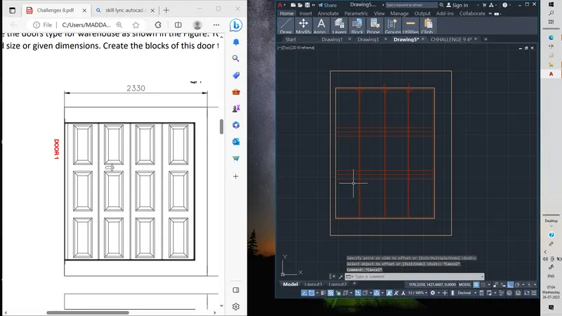
Cereate a style using block command. using rectangle and offset as shown in screenshot below.
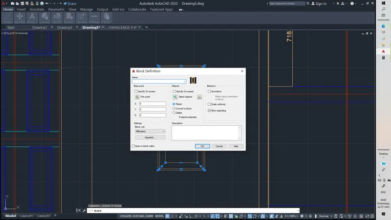
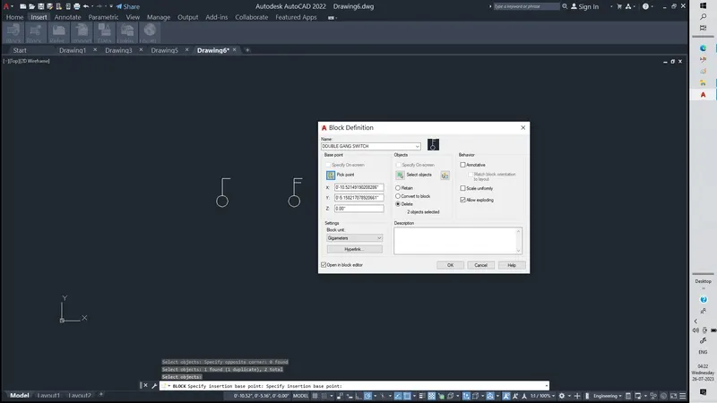
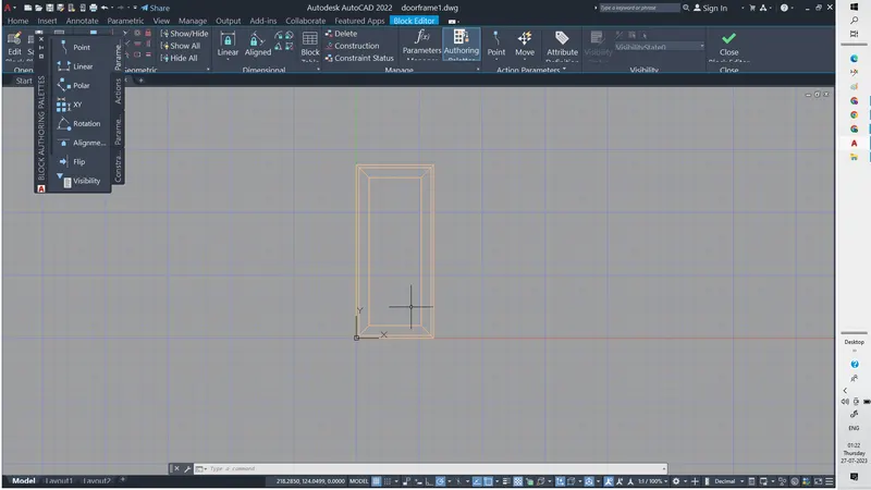
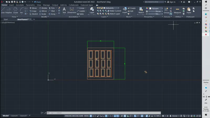 result:
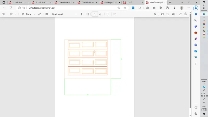
similary draw door frame 2 also steps asshown inm figure above.
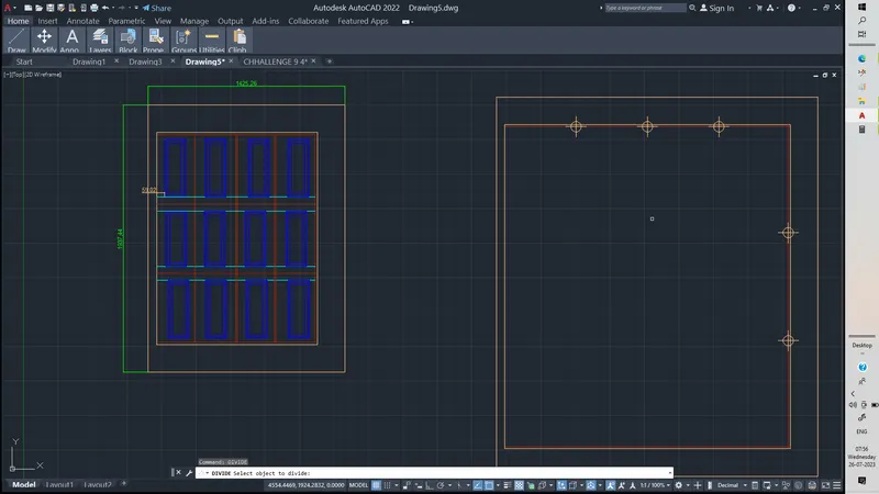
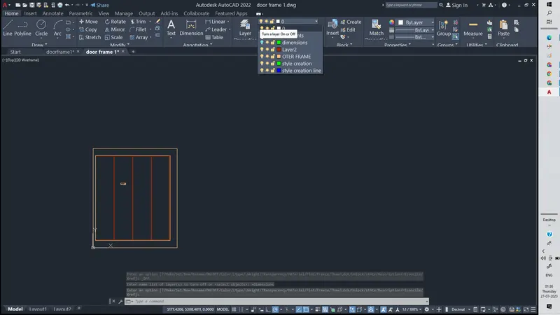
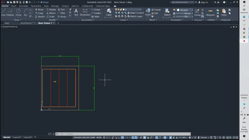
final result
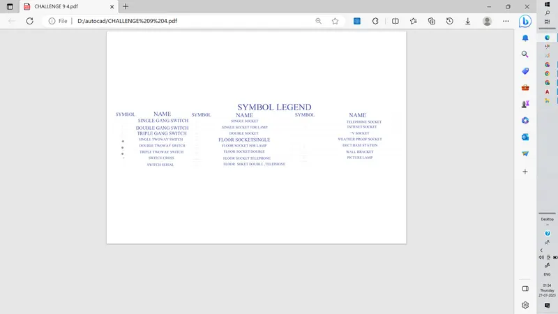
 3. Create each symbol as a block with the name given in the legend. After creating the blocks arrange them in the legend as shown in the Figure.
ans. 1. set units and limits .
Create bloc drawings as per drawing
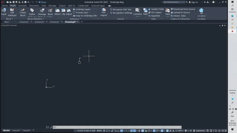
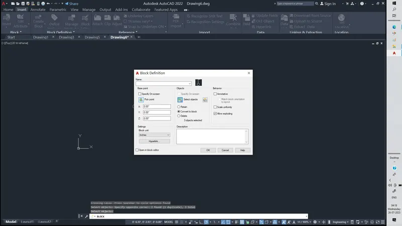
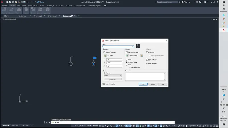
similarly allblocks are created as shown in screen shot above.
Create a table using annoation in riibbon bar as shown shown in screen shot above.
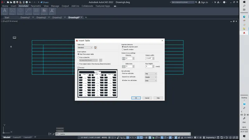
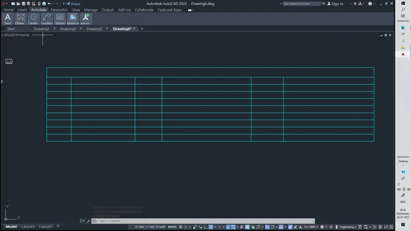
Using insert block from ribbon bar and insert blocks as yoyu required as shown inscreen shot below.
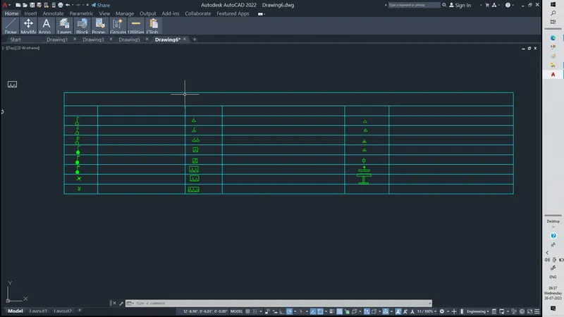
Using mtext command. place the text as you required as shown in screen shot above.
Final result.
4. Create the door type for residential building as a block. Save the name of the blocks as type. Use given dimensions or assume dimensions as per industry standards.
ans. Command s are use d as similarlar in before drawings.
step 1
1. set units of engineering and limits
2. draw a rectangle of dimension 2'10"x 6'11" and draw aoffset of 20mm,10mm as shown in screen shot below.
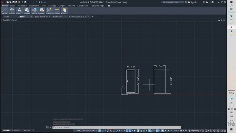
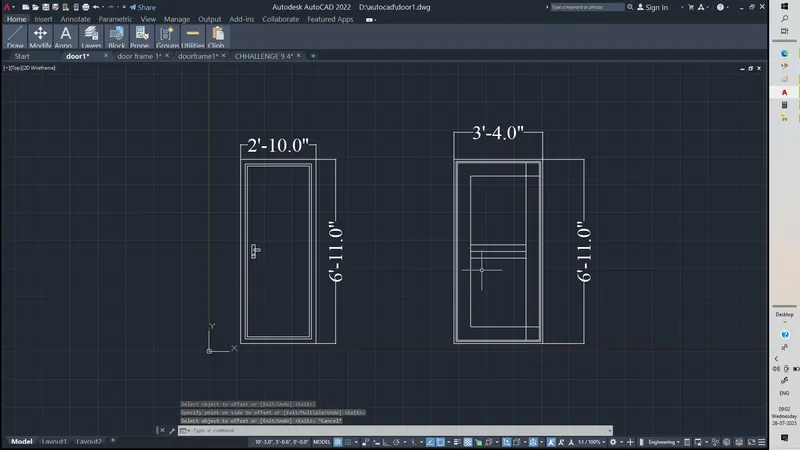
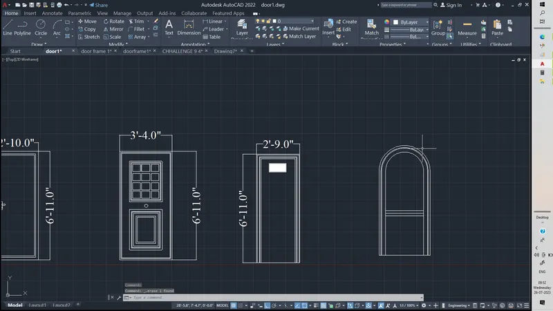
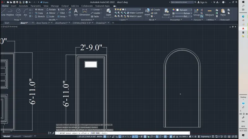
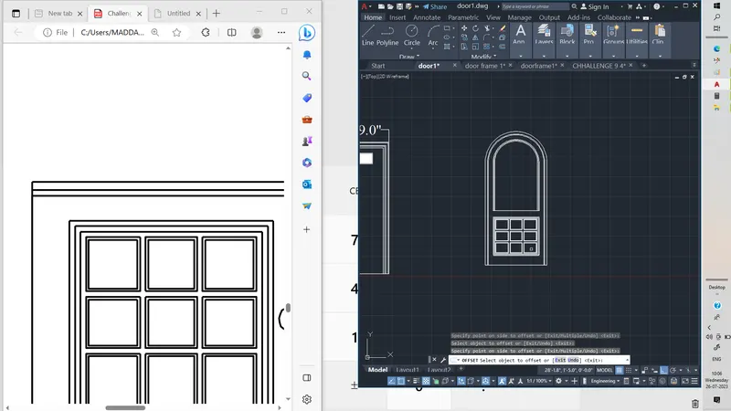
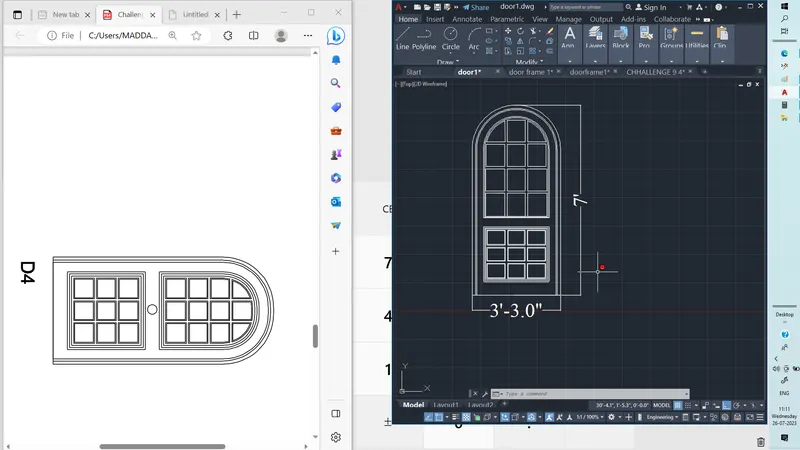
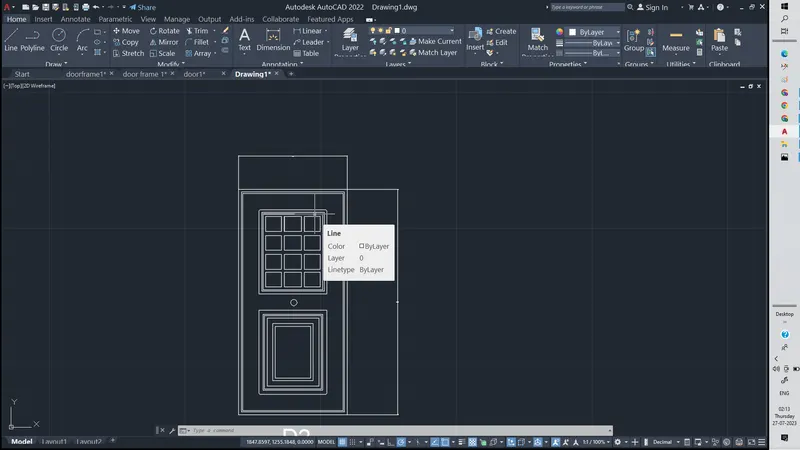
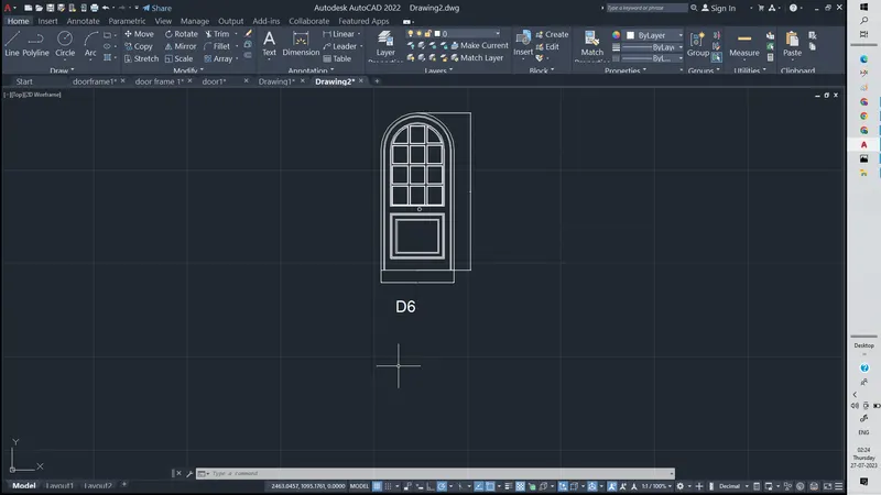
Final result.
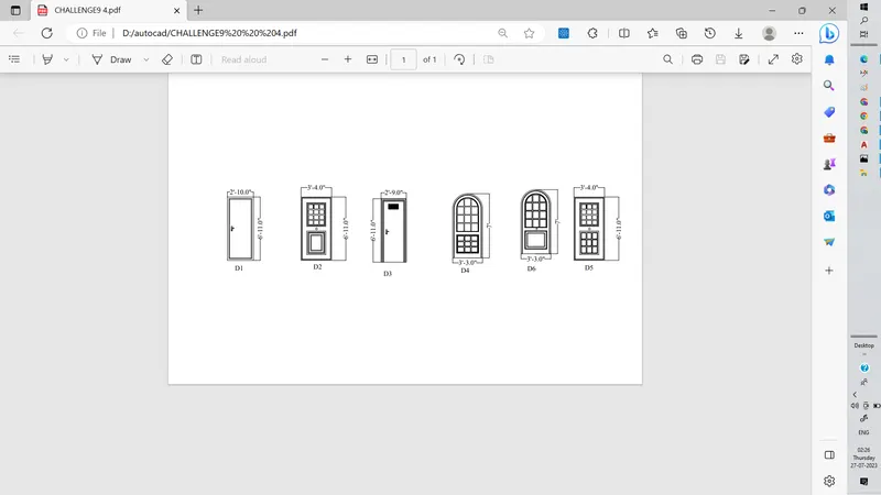
5. Create each shape as a block as shown in the Figure. Save the block and insert them on the table as shown in the Figure.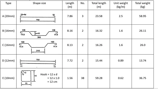
ANS.
Commands are used as before dreawings as sbhwn inabove.
Set units and draw a shpes of reinforcement and block the details as shown in screet shot below.
Draw aline command using using 750mmdimension ans offset of 30mm and fillet and join line with radius of 10mm
Mirror the right sid epart to left side complete it.
Using block command block the elements in to sigle entityas shown inscreen shot below.
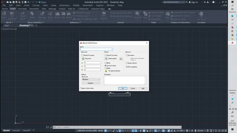
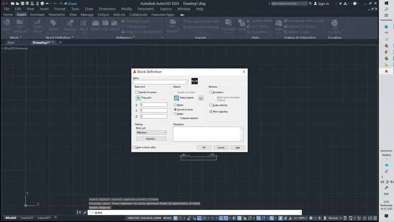
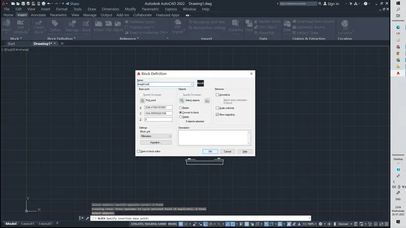
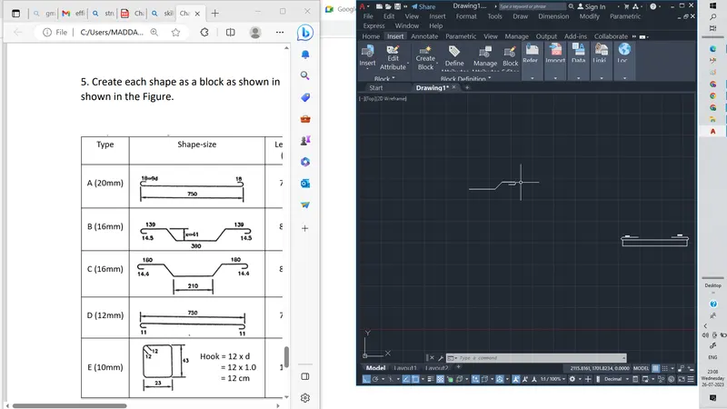
Simalrly all bars are created as ablock and saved.
Step3:
Table creation
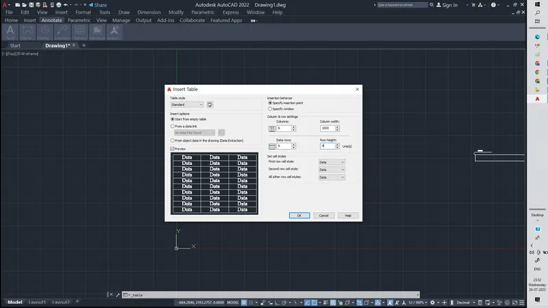
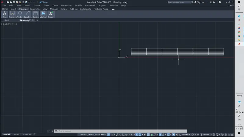
Select anotation in ribbon bar and select table an nd give the no of columns and rows and and click enter and place a pointer on screen then table was created as shown in screen below.
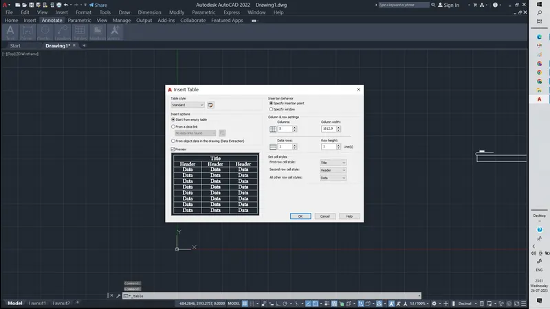
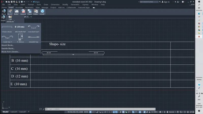
Insert blocks as you need intable as shown in screen shot.
Place a text as you need in table.as shown in screen shot.
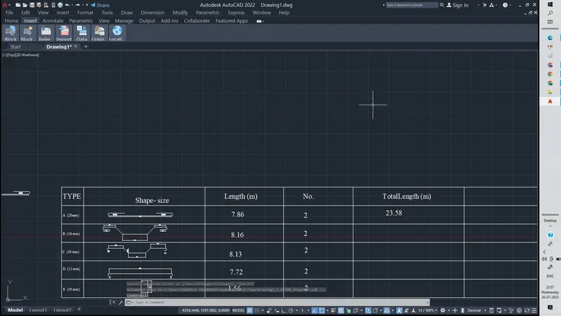
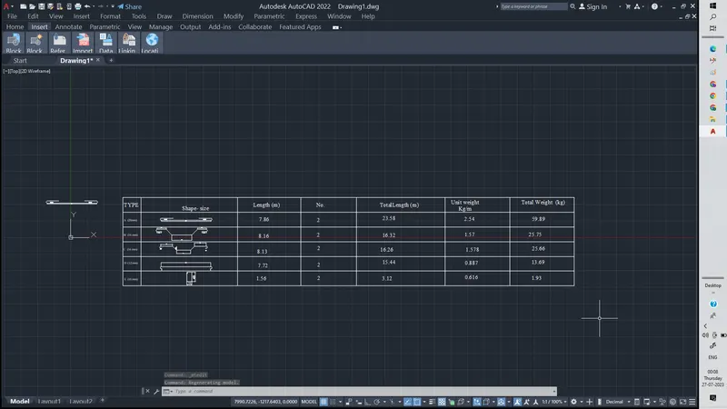
Final result.