Project 2_Creating a 3D rendered model for a Residential Building in AutoCad
Aim: - to create a 3d model of a residential building and render it.
Procedure: -
- Units- decimal.
- Go to 3d modelling workspace.
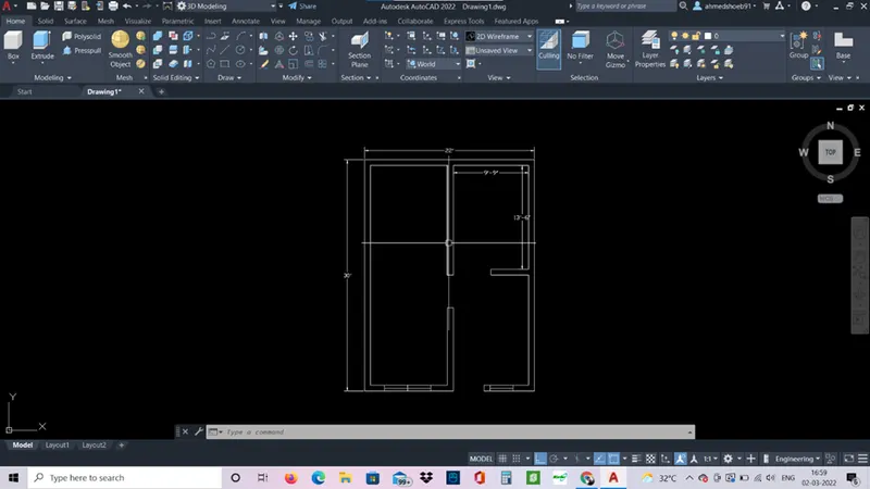
- In the top view, First draw the 2d plan using line, offset and trim command.
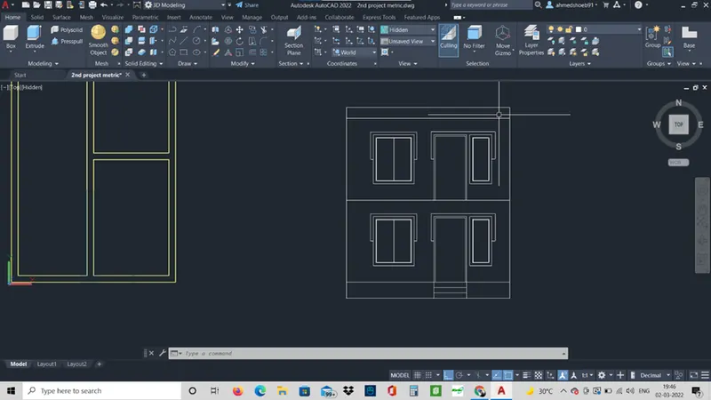
- Also draw the front elevation of the building.
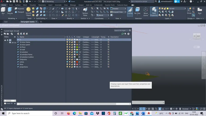
- Now make layers which are required for ex walls, windows, doors projections etc.
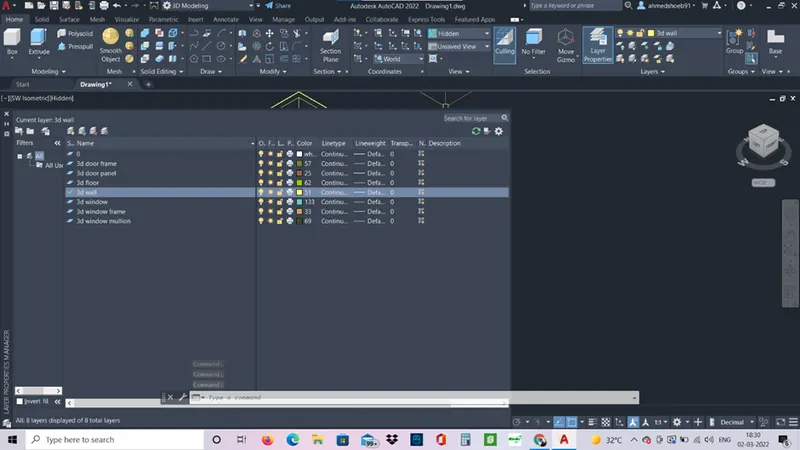
- Give boundary to the walls using boundary command.
- Go in isometric view and select the wall layer and now select the walls and extrude it 3000mm.
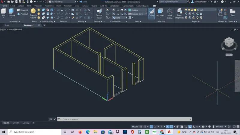
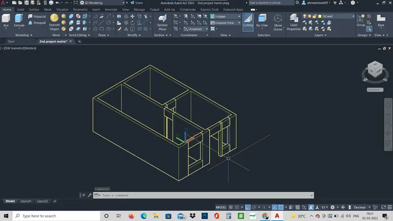
- For windows make a rectangle at the bottom and extrude it 600mm in upward direction.
- Set the ucs on top of the wall draw a rectangle at the opening give it a boundary and extrude it downwards in 600mm.
- Same way door opening is created.
- Now union the walls to make it a single union.
- For front elevation select the front elevation drawing and use 3drotate command and rotate the drawing in z axis at 90 degrees.
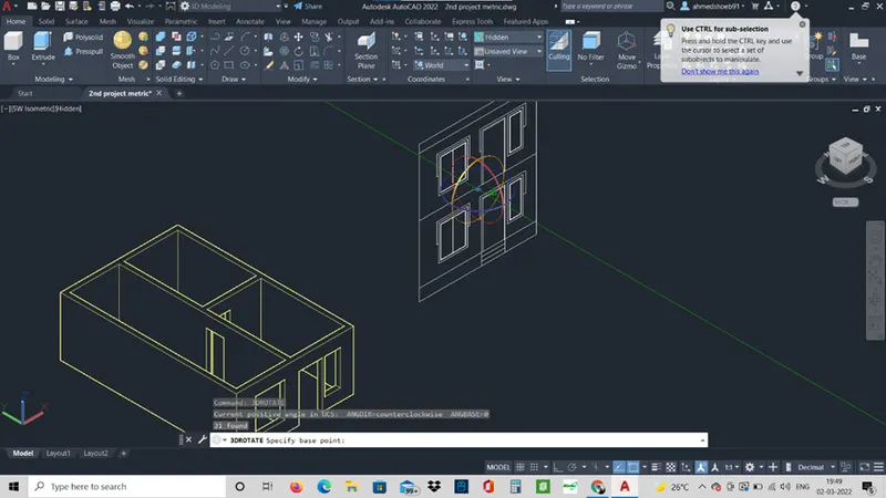
- Delete the extra lines apart from windows and doors. Select each layer and give boundary to it. For ex. Window frame extrude 75mm window mullion 50 mm and window glass as 25mm. similarly make the door frame and door panel.
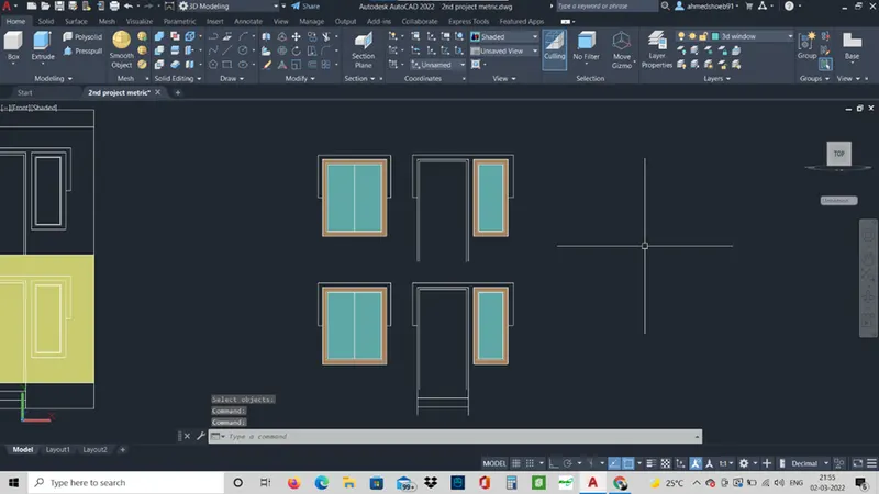
- Now group the windows and doors and copy paste in the window and door openings.
- Windows and doors can be moved inside the opening to show a depth in 3d view.
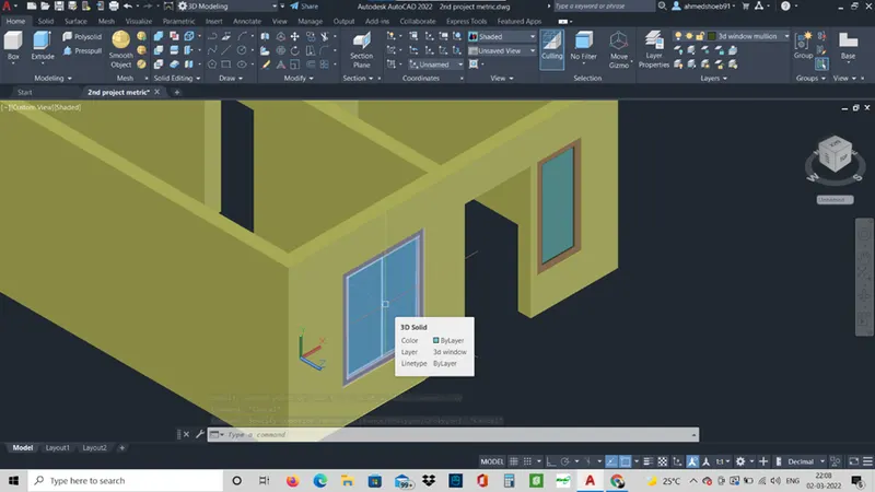
- Set the ucs at world. Go in isometric view. Use layoff command and layer off walls windows and doors.
- Make a rectangle from end to end of the plan, give it a boundary and extrude it 600mm downwards for plinth of the building.
- Cladding of the plinth beam is done by making and rectangle at one corner of the plinth, giving it boundary and extruding it in a path.
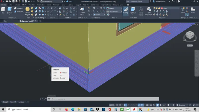
- Use layon command make all layer on.
- Set the ucs at the top of the wall and make a rectangle of the inner wall to wall of the building, give it a boundary and extrude it 150mm for slab in upward direction.
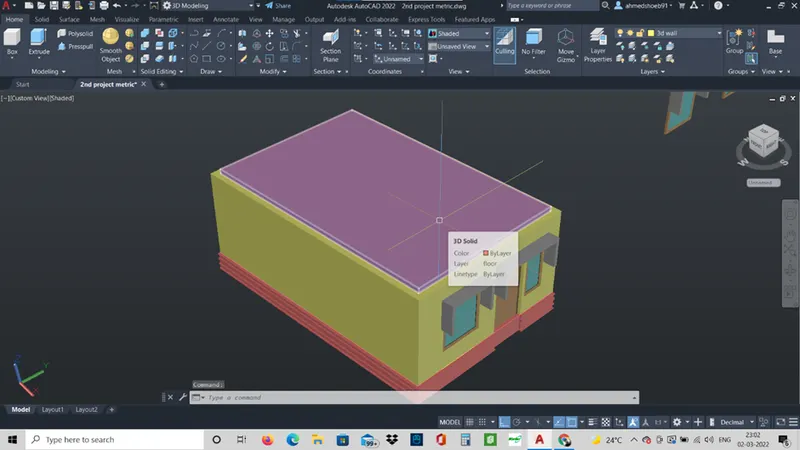
- Now select everything except plinth beam and copy it on top of the ground floor to make first floor.
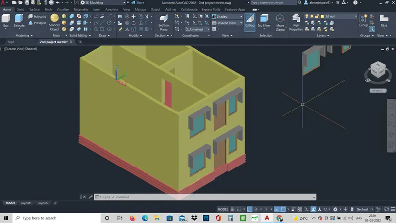
- Set the ucs at very top of the wall make a rectangle move it away from the building, give it a offset of 230mm. give it a region and extrude it 900mm your parapet wall is created.
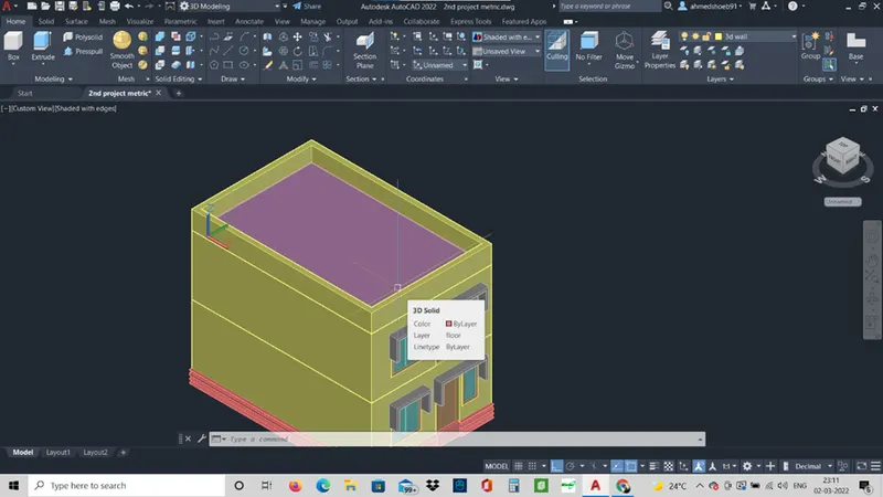
- First make a slab of 150mm on the top and move the parapet wall on the top of the building.
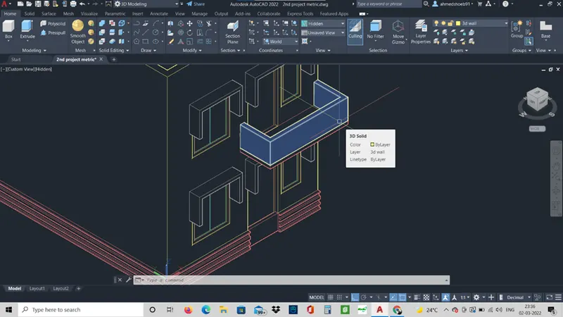
- Balcony is created by setting the ucs on the face of the front wall. Make rectangle extrude the rectangle and set the ucs accordingly to make changes and make a balcony wall. Use solideddit command and make desired changes.
- The 3d model of the building is done.
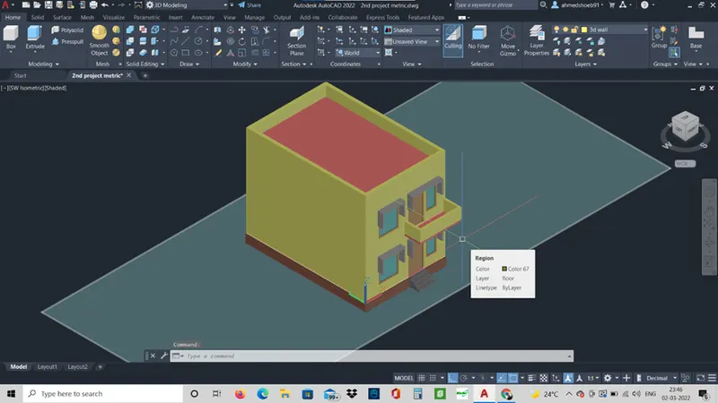
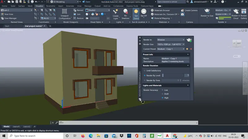
- Now to render the building, first go in visualize in ribbon and create cameras.
- Set a camera accordingly to make a view of the building.
- Go in the camera view and make adjustments using orbit wheel.
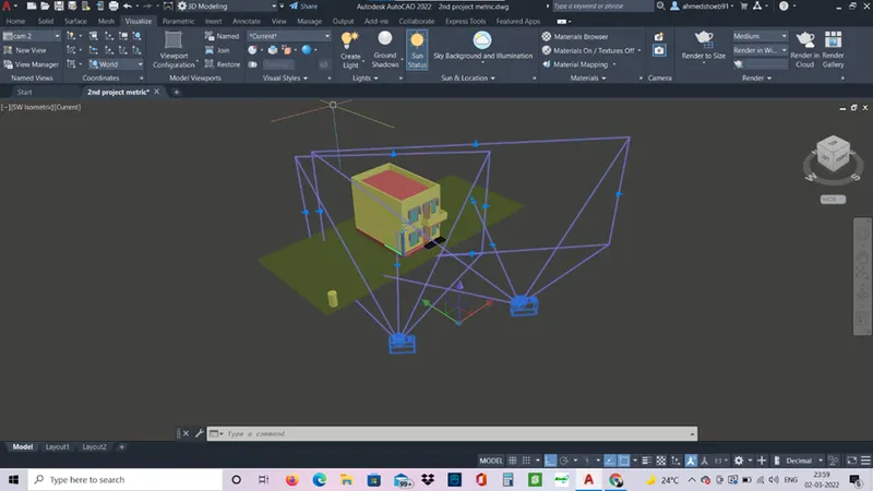
- You can also set lights if required here only sunlight is used.
- Go to material browser and select the materials that are to be given to the objects.
- Use glass materials for window glass, stucco for external wall painting, wood for window frame and door panel etc.
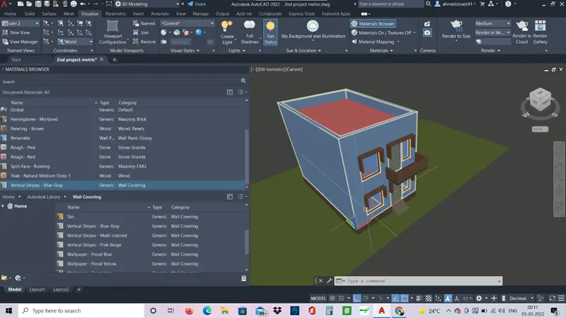
- Once the materials are assigned you can use render command and set the render quality required and render the building using viewport.
- This will make the camera view as the render view.
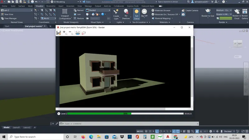
- Rendering is complete.
Result: -
The 3d model of the residential G+1 building is completed and also the rendering of the building by assigning different materials is done in AutoCAD.