Project 1 _Creating an Architectural plan for the provided plot size and develop relevant basic structural drawings
Aim: To design and draft a layout of a residential building facing east with plot size 20’x60’ (18.3 m x 6m) with the following details
- Architectural Drawing (Floor Plan, Elevations and Sections)
- Structural Drawings (Column, beam and footing plan)
Procedure:
- Type QNEW in command box, press enter, select the metric as a default setting.
- Type UN in command box, press enter and choose unit of measurement as decimal unit with the precision 0.
Architectural drawings:
Drawing of ground floor plan:
- Type XL in command box, press enter, select horizontal option from command box and draw the horizontal line.
- Again, type XL in command box, press enter, select the vertical option from command box and draw the vertical construction line.
- Using trim tool trim the extra projected lines.
- Type O in command box, press enter, specify offset distance as 230 units and take offset to the vertical and horizontal lines in inner sides.
- Type F in command box, press enter, select radius option from command box, specify fillet radius as 0 units and fillet the inner lines to create the right bottom corner of plan.
- Type O in command box, specify offset distance 4300 units, press enter and take offset to inner vertical line in right direction.
- Type O in command box, specify offset distance 150 units, press enter and take offset to just drawn offset line in right direction.
- Type O in command box, specify offset distance 3460 units, press enter and take offset to just drawn offset line in right direction.
- Type O in command box, specify offset distance 150 units, press enter and take offset to just drawn offset line in right direction.
- Type O in command box, specify offset distance 4650 units, press enter and take offset to just drawn offset line in right direction.
- Type O in command box, specify offset distance 230 units, press enter and take offset to just drawn offset line in right direction.
- Type O in command box, specify offset distance 4400 units, press enter and take offset to just drawn offset line in right direction.
- Type O in command box, specify offset distance 230 units, press enter and take offset to just drawn offset line in right direction.
- Type O in command box, specify offset distance 2700 units, press enter and take to inner horizontal line in upward direction.
- Type O in command box, specify offset distance 150 units, press enter and take offset to just drawn offset line in upward direction.
- Type O in command box, specify offset distance 2748 units, press enter and take offset to just drawn offset line in upward direction.
- Type O in command box, specify offset distance 230 units, press enter and take offset to just drawn offset line in upward direction.
- Trim the extra lines to create the wall joints.
- Type O in command box, specify offset distance 1800 units, press enter and take offset to just drawn offset line in right direction.
- Type O in command box, specify offset distance 150 units, press enter and take offset to just drawn offset line in right direction.
- Type O in command box, specify offset distance 1500 units, press enter and take offset to just drawn offset line in right direction.
- Type O in command box, specify offset distance 150 units, press enter and take offset to just drawn offset line in right direction.
- Trim extra lines to create wall joints.
- Type O in command box, specify offset distance 3810 units, press enter and take offset to just drawn offset line in right direction.
- Type O in command box, specify offset distance 150 units, press enter and take offset to just drawn offset line in right direction.
- Type O in command box, specify offset distance 2000 units, press enter and take offset to just drawn offset line in right direction.
- Type O in command box, specify offset distance 150 units, press enter and take offset to just drawn offset line in right direction.
- Type O in command box, specify offset distance 3500 units, press enter and take offset to just drawn offset line in right direction.
- Type O in command box, specify offset distance 230 units, press enter and take offset to just drawn offset line in right direction.
- Type O in command box, specify offset distance 150 units, press enter and take offset to just drawn offset line in right direction.
- Type O in command box, specify offset distance 1328 units, press enter and take offset to inner top horizontal line to draw the toilet rooms in downward direction.
- Type O in command box, specify offset distance 150 units, press enter and take offset to just drawn offset line in downward direction.
- Similarly create the top right-side bedroom by taking offset of 2750 units from inner horizontal line in downward direction followed by offset of 150 units in same direction to create inner wall.
- For drawing the staircase, type O in command box, specify offset distance 1200 units, press enter and take offset to inner right vertical line in left direction.
- Again, Type O in command box, specify offset distance 150 units, press enter and take offset to just drawn offset line in right direction.
- Type O in command box, specify offset distance 250 units, press enter and take 9 offsets to just drawn offset line in left direction.
- From right top inner horizontal line take offset of 2400 units followed by offset of 230 units in downward direction.
- Trim the extra lines using trim tool wherever required to create wall joints and also to trim the extra projected lines.
- For drawing the window W draw the line joining midpoints of lines having length equal to the thickness of wall.
- Take offset of 600 in both direction and join the midpoints of offsets.
- Erase the middle line having length equal to thickness of wall using erase tool.
- Take offset of 25 units in both direction of joined line and erase the middle line using erase tool.
- Similarly draw the window W1 having length 1000 and W2 having length 500.
- Type REC in command box and press enter.
- Select the dimension option from command box.
- Specify length as 400 units and width as 230 units and press enter.
- Type H in command box and press enter.
- Select the hatch pattern as ANS137 with the scale 10 and pick internal pints as centers of each rectangle and hatch it.
- Rotate and copy it to required position using rotate and copy tool respectively as per orientation of columns.
- Type ST in command box, press enter, select font name Arial, text height as 200 units and select ok.
- Type MTEXT in command box, press enter, specify first corner, second corner and type the content of text.
- Type CO in command box, press enter, select base point and copy it to required positions.
- Type ED in command box, press enter, select the text required to edit and edit it as per required content.
- Type DIMLIN in command box and give dimensions to the lines by specifying origin of first extension line and second extension line.
- Type DIMCON and continue the dimensions for adjacent lines as shown below.
- Set the unit of dimension as decimal with precision 0 in dimension dialog box and set as current style.
Drawing of first floor plan:
- Type CO in command box, press enter, select the outer walls and stair case and columns of ground floor plan, specify the base point and copy it to another position.
- Type EXTEND in command box, press enter, and extend the lines wherever required.
- Type O in command box, press enter, specify offset distance as 4150, press enter and take offset to inner face of left wall in right direction.
- Type O in command box, specify offset distance 150 units, press enter and take offset to just drawn offset line in right direction.
- Type O in command box, specify offset distance 3110 units, press enter and take offset to just drawn offset line in right direction.
- Type O in command box, specify offset distance 150 units, press enter and take offset to just drawn offset line in right direction.
- Type O in command box, specify offset distance 5150 units, press enter and take offset to just drawn offset line in right direction.
- Type O in command box, specify offset distance 230 units, press enter and take offset to just drawn offset line in right direction.
- Trim the extra lines to create the wall joints.
- Type O in command box, specify offset distance 1120 units, press enter and take offset to bottom left inner horizontal line in upward direction.
- Type O in command box, specify offset distance 230 units, press enter and take offset to just drawn offset line in upward direction.
- Type O in command box, specify offset distance 2850 units, press enter and take offset to just drawn offset line in upward direction.
- Type O in command box, specify offset distance 150 units, press enter and take offset to just drawn offset line in upward direction.
- Trim extra lines to create wall joints.
- Type O in command box, specify offset distance 2000 units, press enter and take offset to left side adjacent inner vertical wall face in right direction.
- Type O in command box, specify offset distance 150 units, press enter and take offset to just drawn offset line in right direction.
- Type O in command box, specify offset distance 2000 units, press enter and take offset to just drawn offset line in right direction.
- Type O in command box, specify offset distance 150 units, press enter and take offset to just drawn offset line in right direction.
- Similarly draw the bedroom by taking offset of 3893 units from top inner horizontal line in downward direction followed by offset of 230 units in same direction.
- Draw the windows wherever required by using similar procedure as mentioned in ground floor plan.
- Type CO in command box, press enter, select the base point and copy the text from ground floor plan and copy it to required position.
- Type ED in command box, press enter, select the text required to edit and edit it as per required content.
- Type DIMLIN in command box and give dimensions to the lines by specifying origin of first extension line and second extension line.
- Type DIMCON and continue the dimensions for adjacent lines as shown below.
Drawing the section -AA
- Type XL in command box and press enter.
- Select the vertical option from command box and draw the vertical projections from walls and columns of plan at the section line.
- Type XL in command box and press enter.
- Select the horizontal option from command box and draw the horizontal line intersecting projected vertical lines.
- Trim the extra projections using trim tool.
- Type O in command box, press enter, specify offset distance 25, select the horizontal line and take offset in downward direction.
- Type O in command box, press enter, specify offset distance as 100 units, press enter, select the just drawn offset line and take offset in downward direction.
- Type O in command box, press enter, specify offset distance as 225, press enter, select the just drawn offset line and take offset in downward direction.
- Type O in command box, press enter, specify offset distance as 300, press enter, select the top horizontal line and take offset in downward direction.
- Type O in command box, press enter, specify offset distance as 500, press enter, select the top horizontal line and take offset in downward direction for drawing the footings
- Type O in command box, press enter, specify offset distance as 2850, press enter, select the top horizontal line and take offset in upward direction.
- Select the same line and take offset of 2100 units in upward direction for lintel level followed by offset of 1100 units to create the sill level from the same line.
- Type O in command box, press enter, specify offset distance as 115, press enter, select top offset line and take offset in downward direction.
- Type O in command box, press enter, specify offset distance as 350, press enter, select the top horizontal line and take offset in downward direction for creating the beam sections.
- Trim the extra projected lines for creating the windows.
- Similarly draw the first floor of height 2850 units.
- Take offset of 2500 unit in upward direction followed by offset of 450 unit in same direction for drawing the headroom.
- Also draw the slab of 115 unit thickness and other components of headroom using line tool.
- Also draw the chhajja using line tool.
- For drawing the steps of stair case draw the projections from first step and last step of flight from plan using XL commands or tool.
- Make sure ortho mode is on.
- Using Pline tool draw the vertical line of 158.33 unit length in upward direction by specifying first point as end point of first step followed by horizontal line of 250 unit length in left direction.
- Type CO in command box and select the whole, step press enter, select the base point as first end point of first step and copy it by selecting the second point as last endpoint of last step for eight times.
- Type MIR in command box, press enter, select all the steps, press enter, specify first point of mirror line as last endpoint of last step and second mirror point as point at same horizontal level.
- Draw the waist slab and landing for stairs using line tool.
- Select the ground floor stairs and copy it using copy tool and place it in required position for creating first floor stairs.
- Type E in command box, press enter, select the extra projected lines and press enter.
- Type CO in command box, press enter, select the base point and copy the text from ground floor plan and copy it to required position.
- Type ED in command box, press enter, select the text required to edit and edit it as per required content.
- Type DIMLIN in command box and give dimensions to the lines by specifying origin of first extension line and second extension line.
- Type DIMCON and continue the dimensions for adjacent lines as shown below.
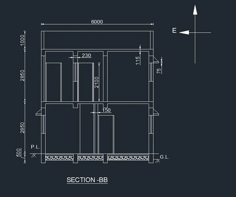
Drawing of section BB
- Type XL in command box and press enter.
- Select the horizontal option from command box and draw the horizontal projections from walls and columns of plan at the section line.
- Type XL in command box and press enter.
- Select the vertical option from command box and draw the vertical line intersecting projected horizontal lines.
- Trim the extra projections using trim tool.
- Type O in command box, press enter, specify offset distance 25, select the vertical line and take offset in right direction.
- Type O in command box, press enter, specify offset distance as 100 units, press enter, select the just drawn offset line and take offset in right direction.
- Type O in command box, press enter, specify offset distance as 225, press enter, select the just drawn offset line and take offset in right direction.
- Type O in command box, press enter, specify offset distance as 300, press enter, select the leftmost vertical line and take offset in right direction.
- Type O in command box, press enter, specify offset distance as 500, press enter, select leftmost vertical line and take offset in right direction for drawing the footings
- Type O in command box, press enter, specify offset distance as 2850, press enter, select the leftmost vertical line and take offset in left direction.
- Select the same line and take offset of 2100 units in left direction for lintel level followed by offset of 1100 units to create the sill level from the same line.
- Type O in command box, press enter, specify offset distance as 115, press enter, select leftmost offset line and take offset in right direction.
- Type O in command box, press enter, specify offset distance as 350, press enter, select the leftmost vertical line and take offset in right direction for creating the beam sections.
- Trim the extra projected lines for creating the windows.
- Similarly draw the first floor of height 2850 units and create the windows and doors wherever required by using offset and trim tool.
- For drawing the parapet wall take offset of 450 units in left direction from the leftmost vertical line and draw the parapet wall of 150 unit thickness using line tool as shown below.
- Type E in command box, press enter, select the extra projected lines and press enter.
- Type RO in command box, press enter, select the entire drawing of section BB, press enter, select base point as bottom right corner of section, specify rotation angle as -90 and press enter.
- The elevation of section BB is as shown below.
- Type CO in command box, press enter, select the base point and copy the text from ground floor plan and copy it to required position.
- Type ED in command box, press enter, select the text required to edit and edit it as per required content.
- Type DIMLIN in command box and give dimensions to the lines by specifying origin of first extension line and second extension line.
- Type DIMCON and continue the dimensions for adjacent lines as shown below.
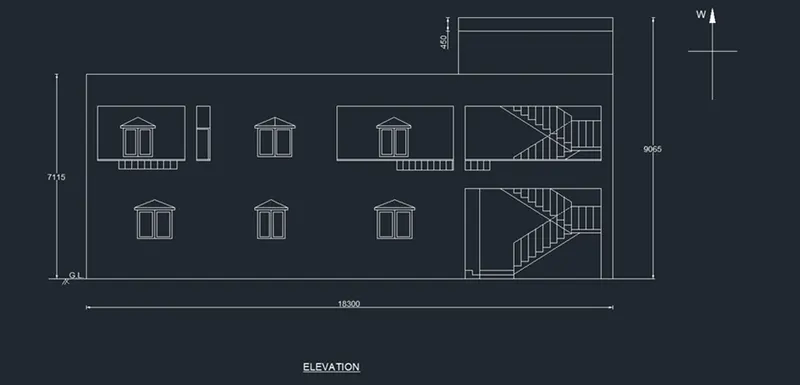
Elevation of building
- Type XL in command box and press enter.
- Select the vertical option from command box and take projections from each component of plan such as windows and doors from the ground floor and first floor plans which is visible in the front elevation.
- Again, type XL in command box, select horizontal option from command box and draw horizontal line intersecting the projected lines which acts as a ground level.
- Type O in command box and press enter,
- Specify offset distance as 300 to create plinth level.
- Using trim tool trim the portion of line which is not in the portico for creating the stairs in the portico.
- Again, type O in command box, press enter, specify offset distance 2850 units and take two offsets in upward direction to the just drawn offset.
- Type O in command box, press enter, specify offset distance as 1000 for creating parapet wall followed by offset of 2500 from the same line in upward direction to create the headroom.
- Type O in command box, press enter, specify offset distance as 2100 to create the lintel level followed by offset of 1100 unit to create the sill level from the same horizontal floor line for each floor.
- Using trim tool trim the extra lines to create the windows elevations of each floor.
- Type XL in command box and press enter.
- Select the vertical option from the command box and draw the projections to start and end point of stair case.
- Type CO in command box and select the staircase elevation from the section AA drawing, press enter, specify base point and copy it to the elevation by specifying appropriate second point.
- Using trim tool trim the extra unwanted lines and part of stairs which is not visible in the front elevation of house.
- Type E in command box and press enter.
- Select all the projected lines and erase it.
- Draw the handrail for staircase using the line tool having the height of 800 units.
- Also draw the handrail for balcony and passage using the line tool.
- Also draw the chhajja using the line tool
- Type DIMLIN in command box and press enter.
- Give the dimensions by specifying first extension line and second extension line origin as shown below.
Structural drawings:
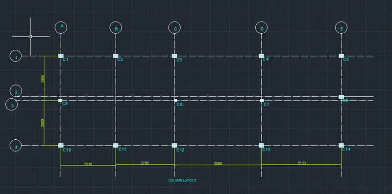
Drawing of layout of column
- Type CO in command box, press enter, select all the columns, along with the outer line of plot area, specify the base point as left top corner of first column and copy it to another position.
- Type LT in command box, press enter, select load option from line type manager dialog box and load centerline type of line.
- For drawing grid lines in property panel of home tab select line type as centerline with line type scale as 50 and draw the gridlines passing through columns and intersecting to each other using line tool.
- Type DIMLIN in command box, press enter and give dimensions for spacing between two grid lines.
- Type DIMCON in command box, press enter and continue the dimension for consecutive lines.
- Type CO in command box, press enter, select the base point and copy the text from ground floor plan and copy it to required position.
- Type ED in command box, press enter, select the text required to edit and edit it as per required content for naming the columns as C1, C2, C3,…, C14 and also give names to each grid lines using alphabets and number.
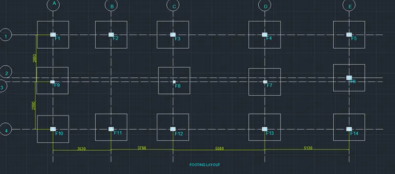
Drawing the layout of footing
- Type CO in command box, press enter, select all the columns along with the outer line of plot area, specify base point as left top corner of first column and copy it to another position.
- Type O in command box, press enter, specify offset distance 900 units and take offset in outward direction by selecting each rectangle which act as column.
- Using trim tool trim the extra projected footing portion.
- Type DIMLIN in command box, press enter and give dimensions for spacing between two grid lines.
- Type DIMCON in command box, press enter and continue the dimension for consecutive lines.
- Type CO in command box, press enter, select the base point and copy the text from ground floor plan and copy it to required position.
- Type ED in command box, press enter, select the text required to edit and edit it as per required content to give the name for each footing as F1, F2, F3,…, F14 as shown below.
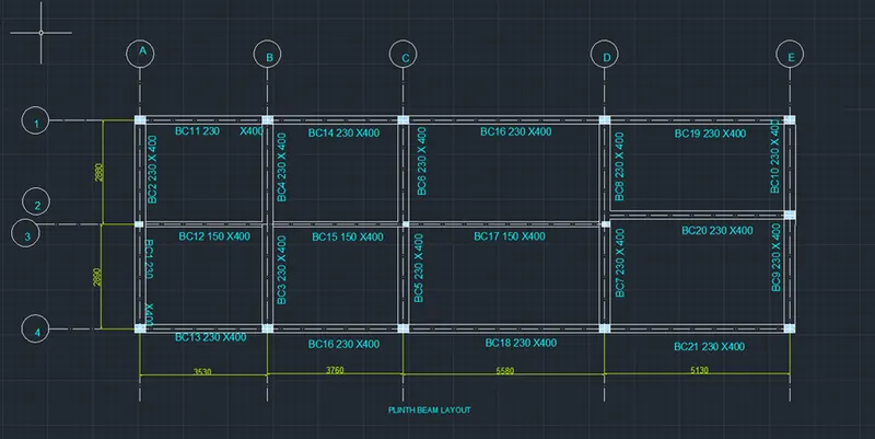
Drawing of Plinth beam and first floor beam layout:
- Type CO in command box, press enter, select the gridlines along with naming of grid lines and rectangles which acts as columns and press enter.
- Specify base point as right top corner of first column and copy it to another position.
- Type L in command box and press enter.
- Draw the lines joining the columns and as per positions of walls having the thickness 230 units and depth 350 units.
- Also draw the secondary beams wherever required using line tool joining the primary beams.
- Type CO in command box, press enter, select the base point and copy the text from upper drawing and copy it to required position to give the names for each beam.
- Type ED in command box, press enter and edit the text as per required content.
- For naming the beams first give names to horizontal beams starting from the bottommost beam followed by upper consecutive beams followed by vertical beams starting from leftmost beam as shown below.
Result:
Architectural drawings:
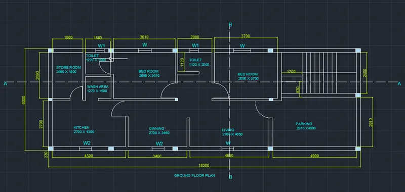
The ground floor plan using above mentioned procedure using AutoCAD software is shown below.
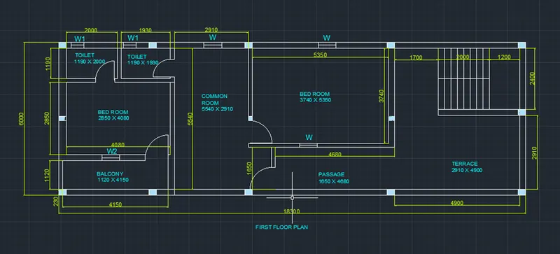
The First floor plan using AutoCAD software by using the above mentioned procedure is shown below.
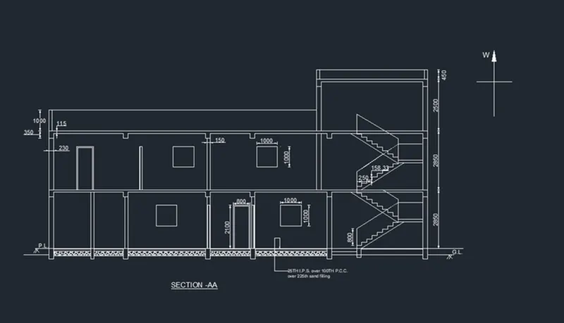
The drawing of section AA using AutoCAD software by using above mentioned procedure is shown below.
The drawing of section BB using AutoCAD software by using above mentioned procedure is shown below
The drawing of elevation using AutoCAD software by using above mentioned procedure is shown below
Structural drawings:
The drawing of column layout using AutoCAD software by using above mentioned procedure is shown below
The drawing of layout of footing using AutoCAD software by using above mentioned procedure is shown below
The drawing of layout of plinth beam using AutoCAD software by using above mentioned procedure is shown below
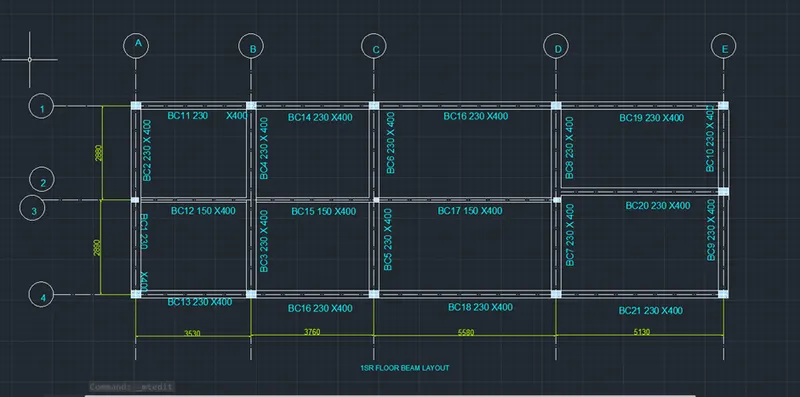
The drawing of layout of fist floor beams using AutoCAD software by using above mentioned procedure is shown below