Project 2_Creating a 3D rendered model for a Residential Building in AutoCad
AIM:
To Create a 3 dimensional model of the residential building with a rendered view using autocad command and tools.
INTRODUCTION:
Create a 3 dimensional model of the residential building with a rendered view.
PROCEDURE:
Under Drawing Units, select Architectural (feet and inches)
The lower limit is now set to 0 ', 0' and the upper limit to 100 ', 100'
Type Z enter to zoom in and A enter them all.
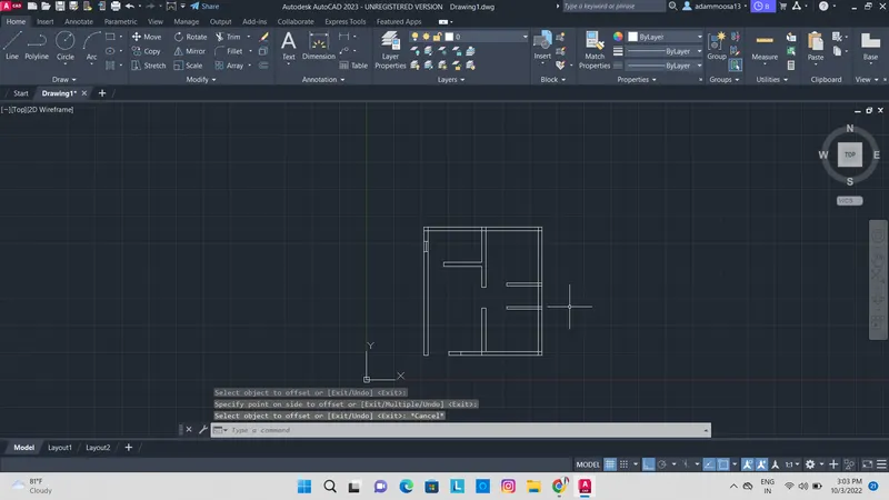
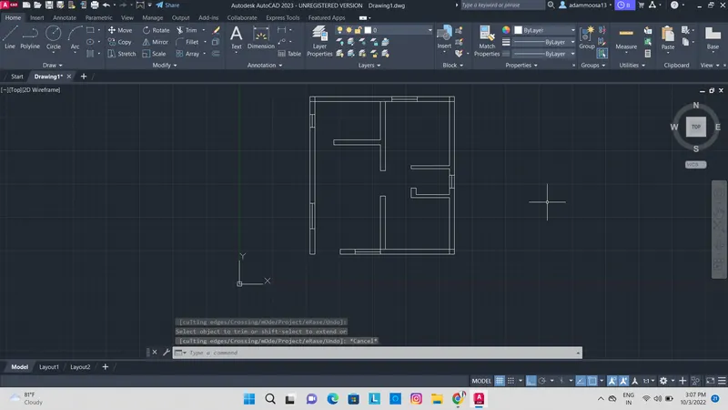
Automatic layers of objects such as walls, windows, grills, steps and stairs, size and text are created and given color.Using the line, rectangle, building lines the layout plan of a single residential building was prepared as indicated.
Doors and windows were provided in the required areas as indicated in the plan.By providing the right style all the necessary documentation is also done.Using the DIMLIM command the size is complete.
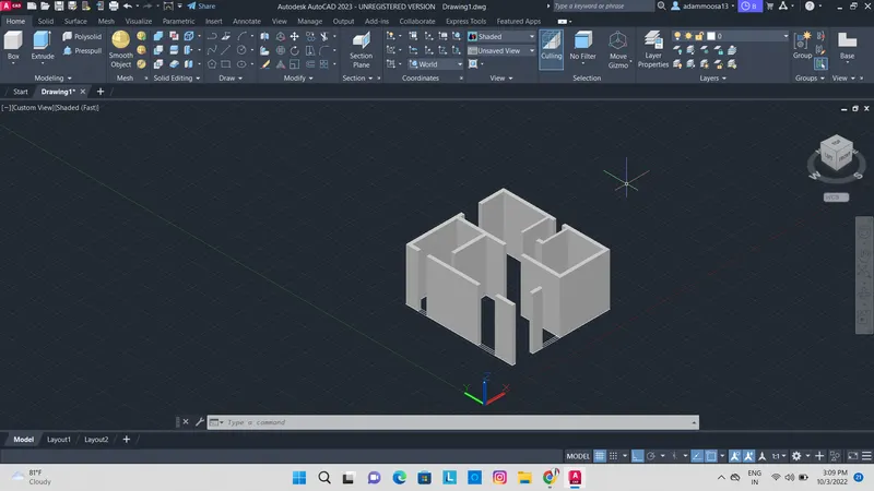
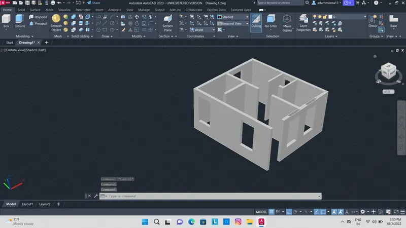
Now in the settings select 3D Modeling and visual style control in 2D wireframe to move to AutoCAD 3D.A copy of the apartment you live in is designed to work with you.Cover all layers except the wall layer.Select the whole drawing and type J to join the entire drawing.Now click the Extrude command on the Home tab and press enter, move mouse up and specify height as 9'6 ”and press enter. A 3D wall is now being built.
After drawing all the rectangles select the Extrude command on the home tab and press enter, move the mouse to the downside and specify height as 2'6 ”and press enter. 7 ’door cutters have now been built.It also means that the lintel beam will be 7 ’height from the plinth level.
Using a REC command rectangle is drawn across the entire window section at plinth level. Select all newly formed rectangles and move the rectangle upwards at 7 ’.All large windows are removed by 4 ’and small toilet windows are removed by 2’ on the floor.
An option is removed from the solid panel to arrange the rectangles of the window out of the wall so window cutting is done.Close the window layer and open the grill layer.In the same way the windows are made rectangular and painted on the level of the plinth on the grills on the balcony.They are then raised by 2'6 ”. Select all rectangles and subtract by 6 ’upwards.The option of removing from the solid editing panel grill cuboids is removed using a wall so a balcony section is made.
Polyline drawing lines are used to connect the outer wall of the building above.Now using the moving command, move the polished polyline down to the plinth level.Using the extrude command remove the polyline by 2 ’which is why you are doing the floor.
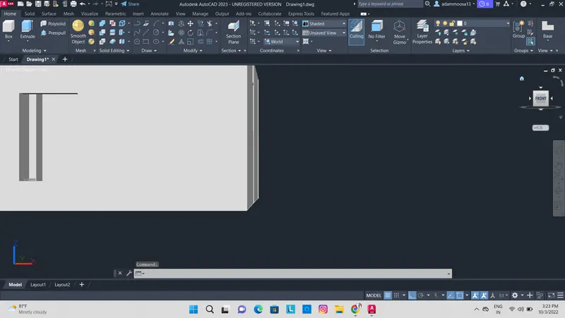
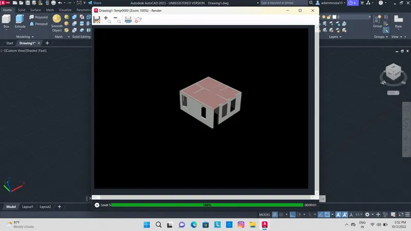
The 3D doors, swinging louver,sliding window, normal window and glass grill was designed using the tools polyline, sweep, extrude, union, 3D rotate, subtract command etc. Rendering was done and the resultant images
RESULT:
Create a 3 dimensional model of the residential building with a rendered view using autocad command and tools is obtained.