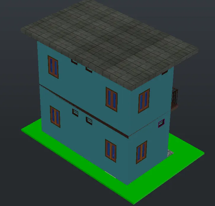
Project 2_Creating a 3D rendered model for a Residential Building in AutoCad
COMMAND USED IN CHALLENGE
- LINE
- RECTANGLE
- TRIM
- COPY
- MOVE
- EXPLODE
- CIRCLE
- MIRROR
- LAYER
- FILLET
- JOIN
- DIMLINEAR
- DIMCONTINUE
- UCS
- 3D ORBIT
- 3D ROTATE
- BOUNDARY
- EXTRUDE
- REGION
- UNION
- SUBTARCT
- CAMERA
- BLOCK
- RENDER RR
- SWEEP
- CREATE LIGHT
AIM :- To create a 3D rendered model for a residential building in AutoCAD.
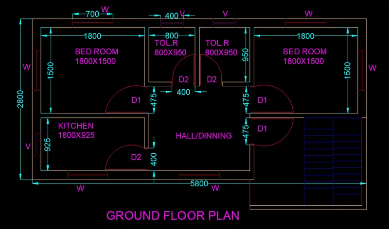
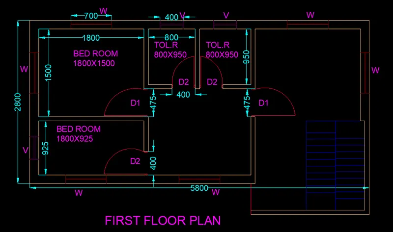
INTRODUCTION :- To create a 3D rendered model for a residential building in AutoCAD. The project is having length 5800mm & width 2800mm and the height of wall is 2800mm. the exterior wall & internal wall having thickness of 150mm & 75mm respectively. This drawing having 2 bed room & 1 kitchen, 2 toilet & hall, veranda near staircase. The size are 1800x1500 mm, 1800x925 mm, 800x950 mm respectively. 5 windows are provided there of 700x1000mm. and ventilator 3 size of 400x300mm. D1 & D2 is represented for door 1 & door 2. D1 = 475x1400mm & D2 = 400x1400mm. stairs are having treads 114.05 & riser 152.4. total length of stairs is 1526mm & width is 1000mm. materials are provided as shown below in procedure section briefly. All dimensions for the drawing is mm. step by step procedure is shown below. This drawing is created by the various command & tools in AutoCAD.
PROCEDURE :-
STEP 01.
- Go to START MENU select AutoCAD
- In Command prompt type STARTUP then enter
- Enter new value of startup as 1
- Go to application menu and select NEW
- Select METRIC, then ok
- Type UNIT command
- In drawing unit dialog box select DECIMAL
- In precision select 0-0
- MILIMETERS in insertion scale then ok
- Select 3D Modelling from the workplace
- Set limits by entering LIMIT command
- Lower-left corner 0,0 and upper-right corner 1000,1000
STEP 02.
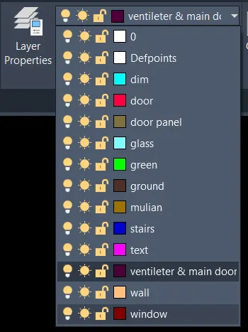
CREATING LAYER
- Create layers by clicking on ribbon tab to layer properties
- Then select the new layers according to your preference
- Layer created as follow shown
STEP 03.
2D VIEW OF PLAN
- Type LINE in command prompt
- Specify first point : click anywhere
- Specify next point : 5800 (X-axis)
- Specify next point : 2800 (Y-axis)
- Specify next point : 5800 (-X-axis)
- Specify next point : 2800 (-Y-axis)
- OFFSET in command prompt
- Offset distance 150
- Offset lines for external wall
- By using LINE command
- Draw internal rooms as shown at respective size
- Now trim unwanted lines
- Now again use LINE command and draw stairs at respective size
- DIMLINER in command prompt show all the dimension’s
- By using LINE & ARC command draw doors & there channels
- MTEXT command for showing there names
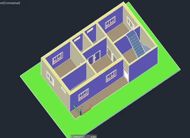
3D VIEW OF PLAN
- Change the view to 3D by clicking on home of view cube
- Create boundaries for the wall by using BO command
- EXTRUDE the boundaries to the height of 2800mm
- Create the boundaries for windows by using BO command
- Now EXTRUDE them to height of 900mm from bottom
- And EXTRUDE from top to height of -900 mm
- Create boundaries at ventilator section by using BO command
- EXTRUDE from bottom 2200mm & from top -300mm
- Now go to conceptual at view bar
- And now use UNION command and make them same section
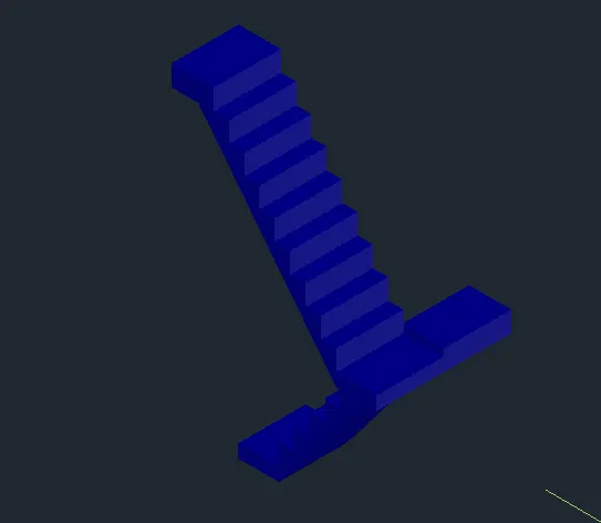
STAIR PLAN
- By using LINE command draw the stairs
- At the size of treads- 114.05 & riser- 152.4 mm
- Now EXTRUDE it to 300mm
- Same thing for 2nd section of stairs by using COPY & 3D rotate command
WINDOW PLAN
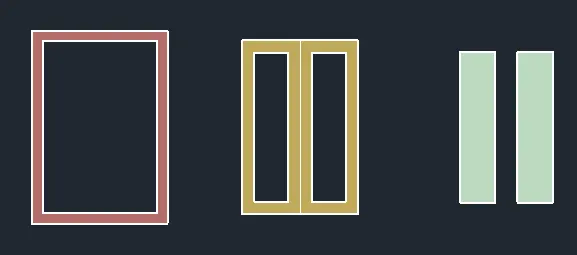
- By using LINE command draw the window section at respective size
- 700x1000mm and make them block or 2 other section like mullion & glass
- Now use BO command and make it as boundaries
- EXTRUDE it to some size at required
- Now use COPY command and make 2 copy of it
- Now use SUBTRACT command one by one for separate section of window
- Now MOVE them and make complete window
- Now use COPY & 3D ROTATE command & place them at respective space
VENTILATORS
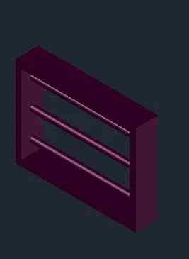
- By using LINE command draw the ventilator
- Size of 400x300mm
- Now use BO command and make it as boundaries
- EXTRUDE it to some height at required size
- Now use COPY command and make 2 copy of it
- Now use SUBTRACT command one by one for separate section of window
- Now MOVE them and make complete window
- Now use COPY & 3D ROTATE command & place them at respective space
- SWEEP command for making rode in ventilator
DOORS
- By using LINE command draw the doors
- Size of D1 = 475x1400mm & D2 = 400 x1400mm
- Now use BO command and make it as boundaries
- EXTRUDE it to some height at required size
- Now use COPY command and make 2 copy of it
- Now use SUBTRACT command one by one for separate section of window
- Now MOVE them and make complete window
- Now use COPY & 3D ROTATE command & place them at respective space
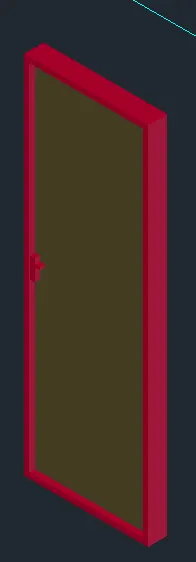
MAIN DOOR
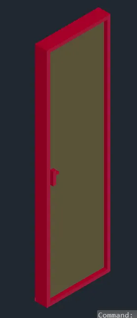
- By using LINE command draw the frame of main door
- Size is 451x1200mm
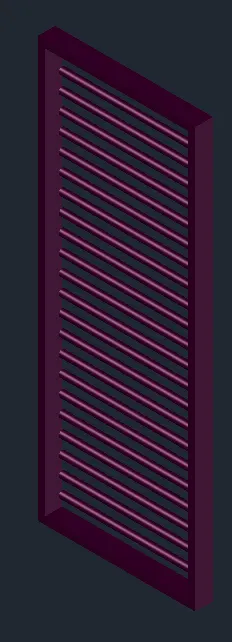
- Now make an horizontal LINE distance from frame 100mm
- Now draw a CIRCLE of Dia-20mm
- And sweep it to the LINE
- now copy at distance of 100 from last cylindrical road
- Now use BO command and make it as boundaries
- EXTRUDE it to some height at required size
- Now use COPY command and make 2 copy of it
- Now use SUBTRACT command one by one for separate section of window
- Now MOVE them and make complete window
- Now use COPY & 3D ROTATE command & place them at respective space
DO THE SAME THING FOR THE FIRST FLOOR BY MAKING SOME CHANGES IN PLAN
RENDERING
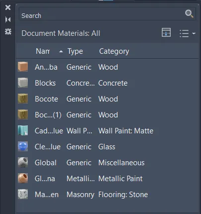
- Select material browser from ribbon
- The material added for component is show below
- Box mapping is done to adjust the texture of the wall
LIGHTS
- Select from the ribbon
- Spot light is placed in front of door at certain distance
- With fall of angle as 50 and hotspot angle as 80
- Distance of light is used to mange the spot light torch
CAMERA
- Select camera from ribbon
- And place it accordingly view direction
- Now watch the view and adjust the camera accordingly
- View comes clear then enter
NOW FOR RENDERING VIEW
- Type RENDER in command prompt
- I was unable to show rendered image cause I have cracked version of AutoCAD.
RESULT :-
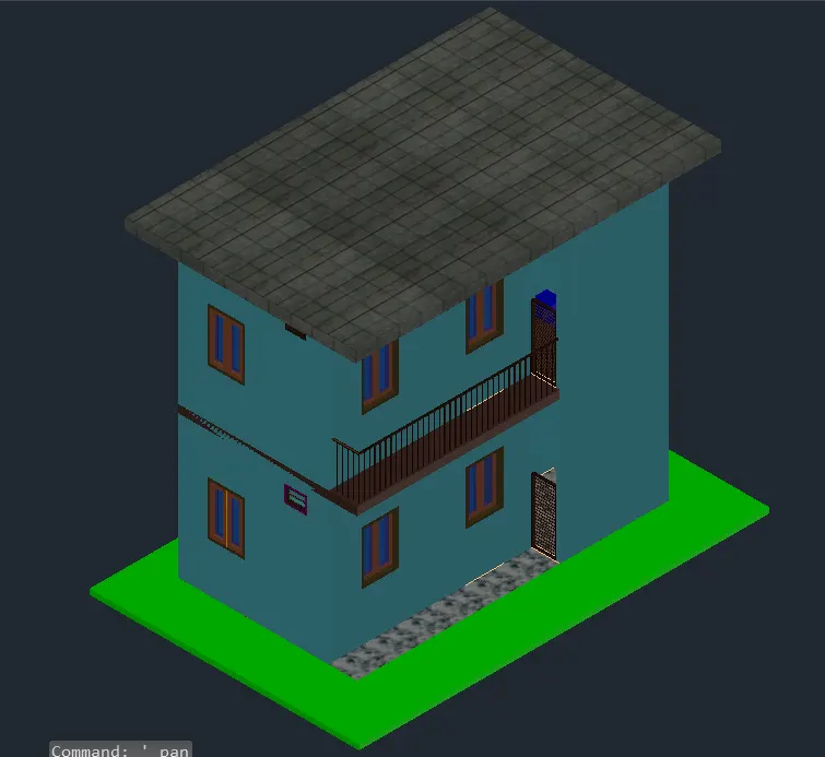
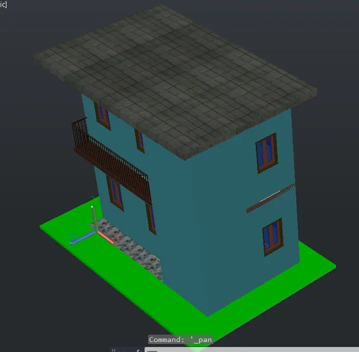
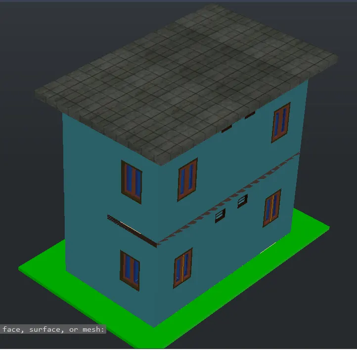
- Created a 3D rendered model of residential building size of 5800mmx2800mm.
- All dimensions are in mm for the drawings.
- The drawing is completed by the using various tools which are mentioned above.
- All drawing & projection is created with the help of AutoCAD software.
SW VIEW
SE VIEW
NE VIEW
NW VIEW