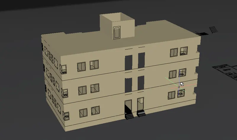
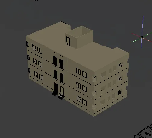
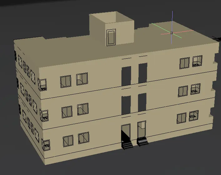
Project 2_Creating a 3D rendered model for a Residential Building in AutoCad
Create a 3 dimensional model of the residential building with a rendered view.
AIM: To create a 3 dimensional model of the residential building with a rendered view.
INTRODUCTION: AutoCAD software provides user to create the 3D models using the various tools and the various commands like the pan command,UCS command and the various commands can be used in the 3D AutoCAD. A user is allowed to use the 3D in AutoCad using the 3D modelling workspace. The 3D AutoCAD makes the 3D creation much easier for the user who are willing to create 3D using the commands and the tools used in the AutoCAD software. In this section we will be able to understand how to create the isometric views in the 3D modelling space using the various tools and the various commands that are helpful in creating the 3D model. The detailed process have been discussed below.
PROCEDURE:
- So in order to create the 3D model of the residential building with the rendered view,first of all go to the AutoCAD software.
- Open the software and then select the option scratch and then open a new file option and then press Enter.
- After opening the new file we have to set the units and the limits.
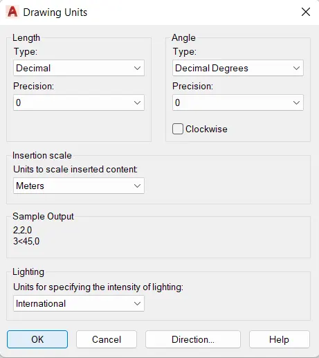
- So in order to set the units just type UN in the command line and then press Enter.
- A new dialouge box appears on the screen, in that dialouge box there will be an option called Length.
- In that option there are two more option called Type so in that box Select the type as Decimal and the other option is Precision so in the precision option give the precision option as 0.
- There will be another option called Insertion scale, so put Meters in that option and then press OK as shown in the below figure:
- So after setting the Units we have to set the limits.
- So in order to change the limits just type LIM in the command line and then press Enter.
- Now set the lower left corner as the 0,0 and the upper right corner as the 20000,20000 and then press Enter.
- After setting the limits and the units we have to zoom out so in order to do so,just type z in the command line and then type e in the command line and then press enter. Now the workspace have been zoomed out.
- Now we have to create the plan,first of all select the top view because we have to create the 2D floor plan first and in order to create the 2D plan we need to set the 3D modelling space into the Top view.
- So draw the plan using the different AutoCAD tools or various commands that are available to make our work more easier.
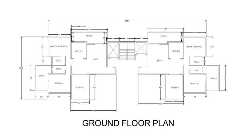
- I have already drawn the plan as shown in the below figure:
- GROUND FLOOR PLAN:
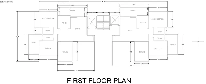
- FIRST FLOOR PLAN:
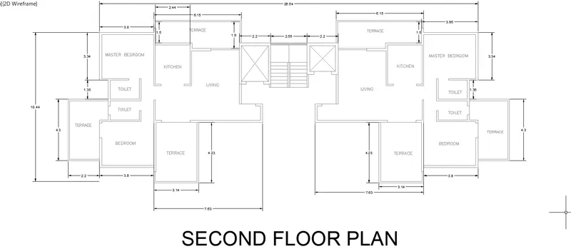
- SECOND FLOOR PLAN:
- TERRACE PLAN:
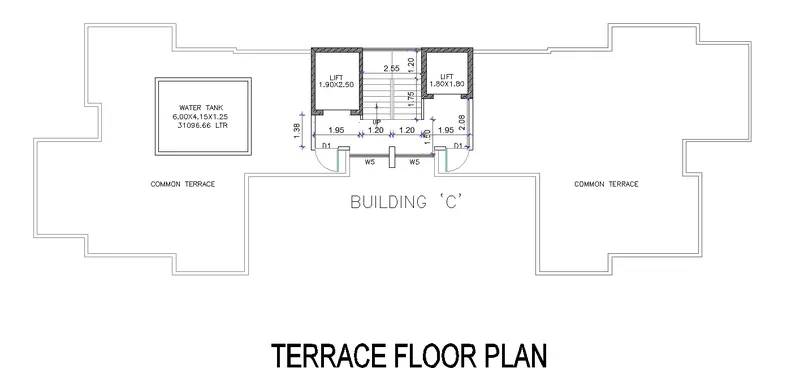
- This is the G+2 residential plan,the ground floor,first floor,second floor and the terrace plan.
- So after creating the plans we have to give the wall and the door schedules also as i have provided in the below table:
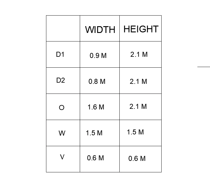
- Now after providing the doors and windows schedule we will start working on the 3D plane in order to create the 3 dimensional residential building.
- Now the plan view is ready as we can see in the above figures.
- Now using this plan view we have to create the 3D view.
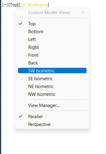
- Now after creating the plan in the top view now we have to change the view into the SW isometric view.
- And to change the SW isometric view we just need to click on the option 2D wireframe which is at the left upper corner of the screen,just from there choose option SW isometric as shown in the below figure:
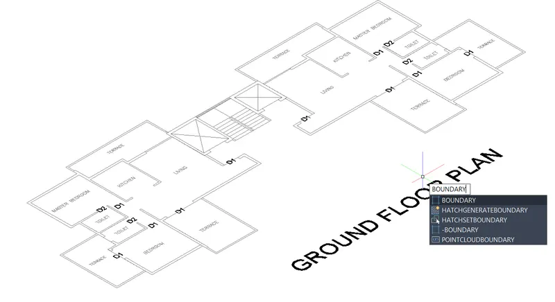
- After changing the view into 3D isometric view,we have to set the boundaries to create the 3D wall.
- And in order to set the boundary we need to just type BOUNDARY in the command line and then press Enter.
- A new dialouge box appears on the screen as shown in the below figure:
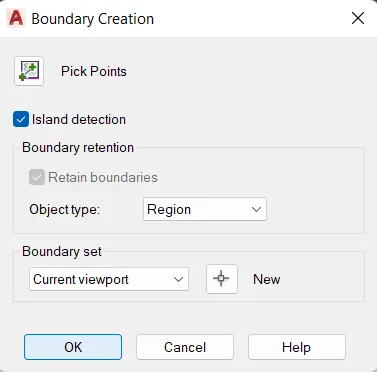
- And after clicking on the OK option just pick the points where we want to set the boundaries,i have selected the boundaries as shown in the below figure:
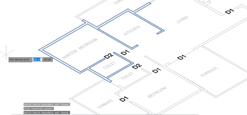
- The selected area above is the area where we want to set the boundaries and to create the wall.
- In the above figure a very small area i have selected in order to show how to pick the boundaries,but we have to do the same procedure for whole plan.
- Similary do the same procedure on all the walls which we want to create the wall.
- And to create the wall we will be using the Extrude command, in order to use the Extrude command just type EXT in the command line and then press Enter and place the cursor where we want to do the extrution as shown in the below figure:
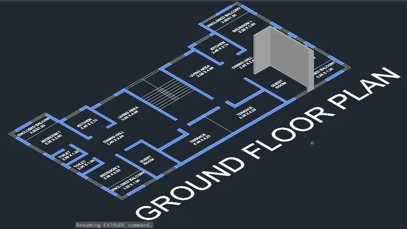
-And then press Enter.
- After pressing the enter give the dimensions to upto which level we want to extrude the walls.
- So here i am giving the height of 3 m as shown in the below figure:
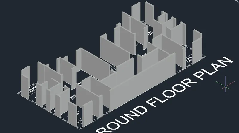
- Now the extrution of the walls have been done using the Extrude command as shown in the above figure.
- Now the walls have been created now we have to draw the windows.
- So in order to draw the windows first of all we need to use the Rectangle command and to use the rectangle command first we need to invoke the rectangle command just by typing REC in the command line and then press Enter.
- So after that just draw a rectangle on the windows that we had created before,draw a rectangle.
- After creating rectangle command just use the Extrude command once again in order to create the window.
- So to use the Extrude command just type EXT in the command line and then press Enter and place the cursor where we want to do the extrution, so place the cursor on the rectangle which we have created over the window.And do the extrusion.
- First give the height of 0.9m from the bottom in the upward direction as the sill level and the 0.9 from the top in the inward direction as the lintel level just as shown in the below figure:
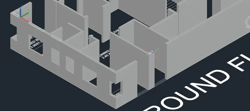
- Now we have to draw the windows,in order to draw the windows on both the walls first of all we need to use the UCS option and to invoke the UCS command just type UCS in the command line and from the command line there is another option called FACE select that option.
- And now select the desired face of the wall and draw the window.
- In order to draw the window we need to need to use the rectangle command and to invoke the rectangle command just type REC in the command line and then press Enter.
- Now specify the first point.
- And type d in the command line and then press Enter.
- Now give the dimensions as the size of the window is 3' X 4'.
- After creating the rectangle of 3' X 4' we need to use the offset tool to create the inner rectangle using the offset command.
- In order to use the offset command just type OFF in the command line and then press enter and give the offset diatnace as 3" and then select the rectangle and give the offset of 3" in the inner side of the rectangle which we have just created of dimension 3' X 4'.
- Then again use the offset command and give the offset distance as the 3" and offset the last created rectangle in the inward direction and then press enter.
- Now after creating the offsets the boundaries of the windows have been created.
- After creating the boundaries we need to use the hatch command in order to create a good aesthetical look for the window.
- So in order to use the Hatch command just type HATCH in the command line and then enter. After that a new dialouge box opens in that dialouge box select the suitable hatch to provide at the window and use the pick point option to create hatches in the windows.
- So now as we can see in the below figure that the windows and the walls have been created successfully using the extrude and the boundary options.
- So below is the given picture of the completed walls and the windows:
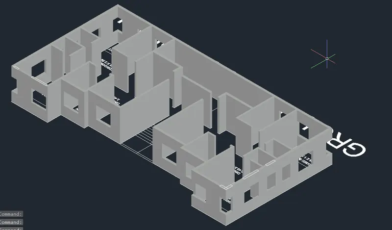
- And similarly do the same procedure for the first and the second floor.
- Now as we can see that the walls and windows are not connected to each other,uptil now they are seperated blocks because i have created them separately.
- So in order to create the walls and the windows as one unit we must use the union command here.
- So in order to use the union command just go to the Home tab and there we will be able to find the option called Union just click on that option as we can see in the below picture:

- After clicking the union option select the area or the elements which we want to make it as single element and then press Enter.
- Now after clicking the Enter evedry single block that are not combined with each other now works as a single unit as shown in the below figure:
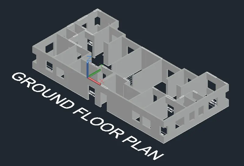
- Now after creating the walls and the windows now we have to create the stairs.
- Now using this plan view we have to create the 3D view.
- Now after creating the plan in the top view now we have to change the view into the SW isometric view.
- After changing the view into 3D isometric view,we have to set the boundaries to create the staircase.
- In order to set the boundary we need to just type BOUNDARY in the command line and then press Enter.
- And then press Enter.
- After pressing the enter give the dimensions to upto which level we want to extrude the stairs.
- So here i am giving the height of 0.15.
- Again use the extrude command and give the height of 0.3.
- Similarly again use the extrude command and give the height of 0.45 for the third tread.
- Do the same procedure untill the last step including the landing as shown in the below figure:
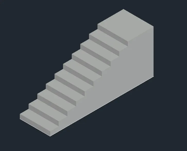
- Now use the option command Solid union.
- Just go to the Home tab, there we will be able to find the option solid union as shown in the below image:
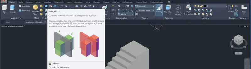
- We use the solid union option to combines the 3D solids so if we select the stairs we can see in the below image all the blocks are separate, so in order to combine them we need to use the solid union option.
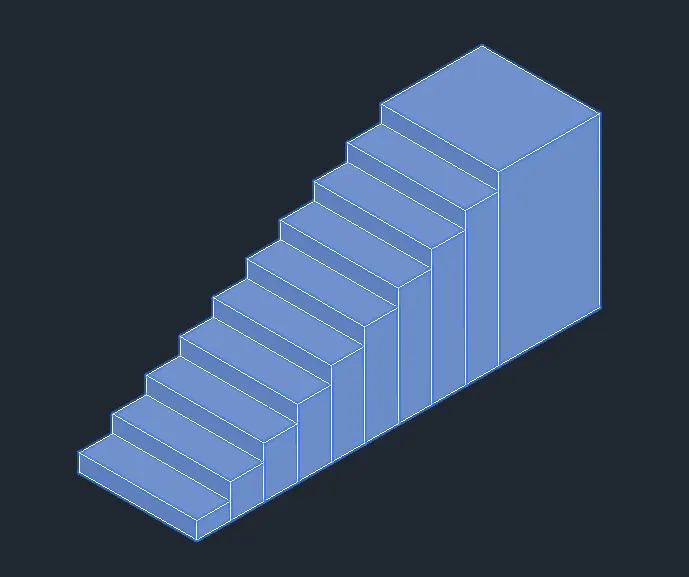
- So in order to do that just select the whole 3D solid i.e, staircase and just click on the option solid union and now all the blocks that are separated before are now combined as shown in the below figure:
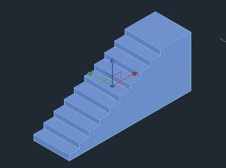
- After combining all the blocks, now we are going to use the Presspull command to pull out the extra part of the stair.
- So to use the presspull command just go to the Home tab there we will be able to find the option presspull as shown in the below image:
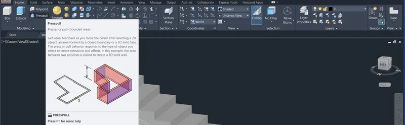
- By using the presspull command we can pull out the extra part of the staircase as shown in the below image:
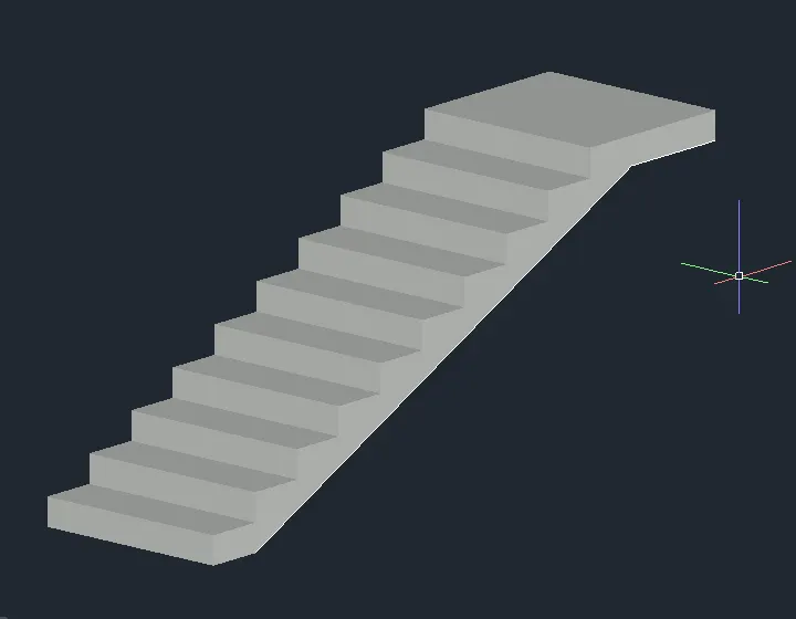
- Do the same procedure for the next flight of stairs as shown in the below figure:
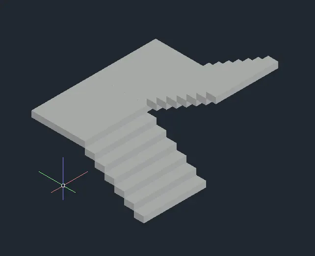
- After that we have to create the railings we need to use the 3D polyline. And we can find the polyline in the Home tab as shown in the below figure:
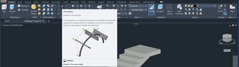
- Now draw a line at the edge of the stair using the 3D polyline.
- Now that we have created the stairs with the proper railings and everything.
- Now we have to create the floors.
- In order to create the floor we will be using the 3D polyline in order to create the boundaries for the floor.
- So to use the 3D polyline to create the boundaries we just need to type 3DPOLY in the command line and then press Enter.
- The 3D polyline invokes, after invoking the 3D polyline we first need to create the boundaries for each floor so first lets see how to create the floor of first floor.
- So go to the first floor plan,then specify the first point there and create the polyline untill the endpoint of the plan. And finish the boundary of the floor using the 3D polyline.
- Now after creating the boundary of the floor,now use the command BOUNDARY to create the boundaries of the created floor plan boundaries as shown in te below figure:
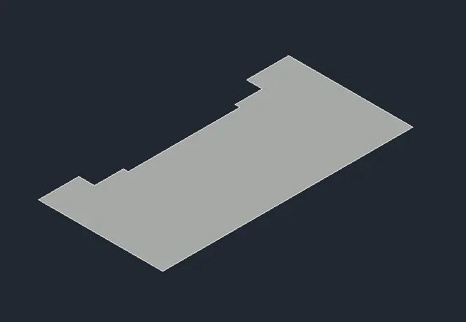
- And to create the floor we will be using the Extrude command, in order to use the Extrude command just type EXT in the command line and then press Enter and place the cursor where we want to do the extrution as shown in the below figure:
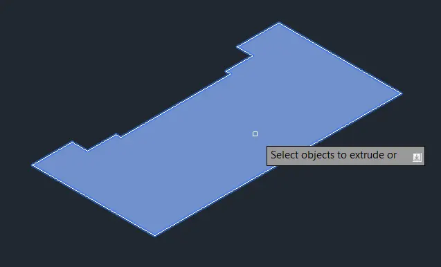
- The above figure shows the object which we want to extrude is selected.
- Now after selecting the object which has to be extruded now we will be able to extrude the object.
- I am giving the extruded height as 0.5 m as shown in the below figure:
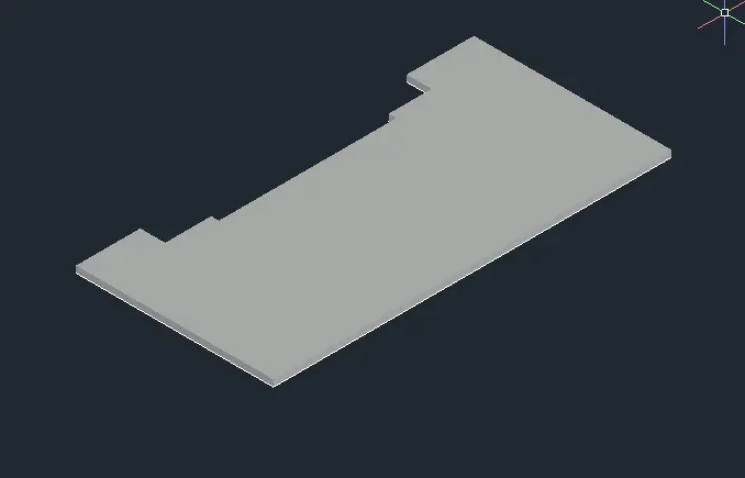
- Now the floor has been created using various commands like Extrude command,3D polyline,boundary etc.
- Now we have to use the copy command in order to put the floor at the desired place.
- So in order to use the copy command just type CO in the command line and then press Enter.
- Select the object and then Enter.
- Now specify the base point and place the floor slab at their required places.
- Do the same procedure for all the floors as shown in the below figure:
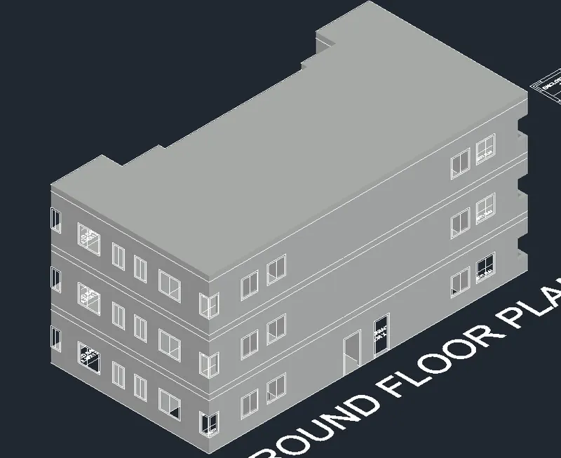
- Now after creating the floor slab and the copying the first floor over the ground floor and the second floor over the first floor no we need to create the roof and the head room.
- So in order to create the head room at the roof we first need to draw the otline of the floor using the 3D polyline.
- So in order to invoke the 3D polyline just type 3DPOLY in the command line and then press Enter.
- Now create the outline using the command and then create the headroom in 2D and then just use the Boundary command.
- So go to the ground floor plan,then specify the first point there and create the polyline untill the endpoint of the plan. And finish the boundary of the floor using the 3D polyline.
- Now after creating the boundary of the floor,now use the command BOUNDARY to create the boundaries of the created floor plan boundaries as shown in the below figure:
- And to create the floor we will be using the Extrude command, in order to use the Extrude command just type EXT in the command line and then press Enter and place the cursor where we want to do the extrution as shown in the below figure:
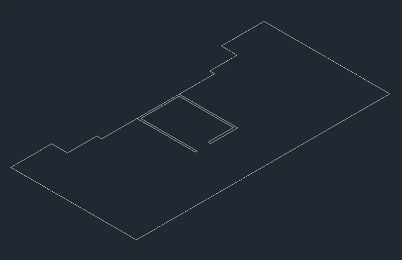
- The above figure shows the object which we want to extrude is selected.
- And now extrude the walls for creating the head room.
- Just type Boundary in the command line and then press Enter.
- After clicking on the boundary command there will be another dialouge box in that dialouge box choose the option region and then click OK.
- After that go to the floor plan just click in the middle of the plan and the outline will become blue if it will get selected.
- Now the floor plan has been selected as boundary just click on that and the boundary has been made.
- Now do the same procedure for creating the head room walls,just make the boundaries and then extrude the wall upto the required height.
- In order to use the Extrude command we just go to the Home toolbar where we can see the option Extrude or we can just type EXT in the command line and then press Enter.
- In either way we can invoke the Extrude command.
- Now that the extrude command is invoked just do the extrusion for the wall and the floor slab.
- Just give the height of 3m for the head room wall and the 0.6 m for the floor slab now we have done creating the floor slab for the terrace and the head room as shown in the below figure:
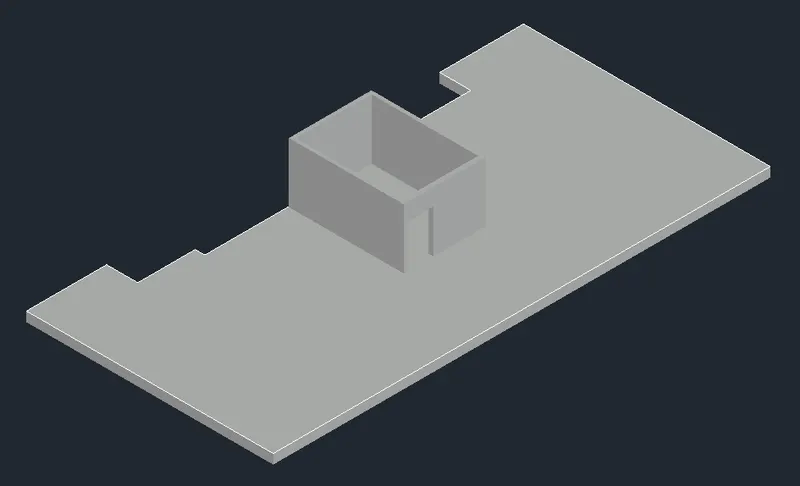
- So now use the move command to move the floor slab and the headroom.
- In order to use the move command just type MOVE in the command line and then press Enter.
- Now specify the base point and move it to the desired location as shown in the below figure:
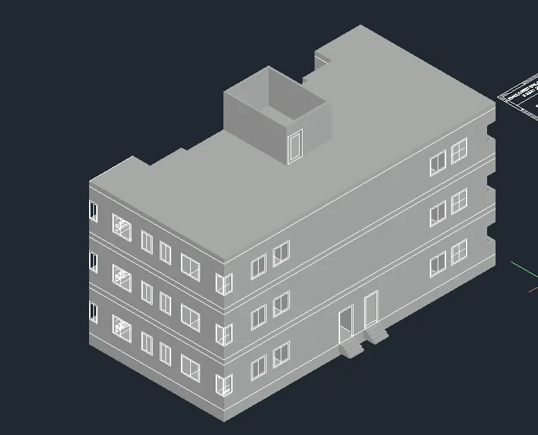
- Now this is how it will be looking like after creating the floor plan.
- Now we have to use the camera view also.
- So in order to create a camera view, just draw a circle anywhere and place the camera on that.
- So in order to draw a circle just type C in the command line and then press Enter.
- Now draw a circle of suitable size and after creating the circle just type CAMERA in the command line and then press Enter. As shown in the below figure:
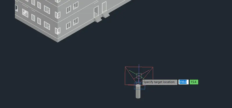
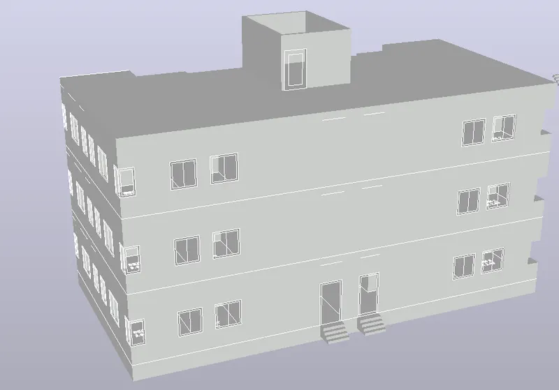
- And now place the camera on that circle and just click on the option Camera view and then enter after clicking on the enter button the result of the camera view has been shown in the below picture:
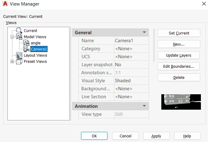
- After this just set the View,and to set the view we must type V in the command line and then press Enter.
- A new dialouge box appears on the screen called View manager in that box just select the option Cam 1 as this is the first picture using the camera so thats why its came 1 as shown in the below figure:
- We can also use the Navigation wheel in order to adjust the views of our project.
- And with different angle we can save the view as Cam 2,Cam3 and so on.
- Now after setting the views we have to assign the materials also.
- So in order to do so just type MAT in the command line and then press Enter.
- A new dialouge box appears on the screen as Material browser as shown in the below image:
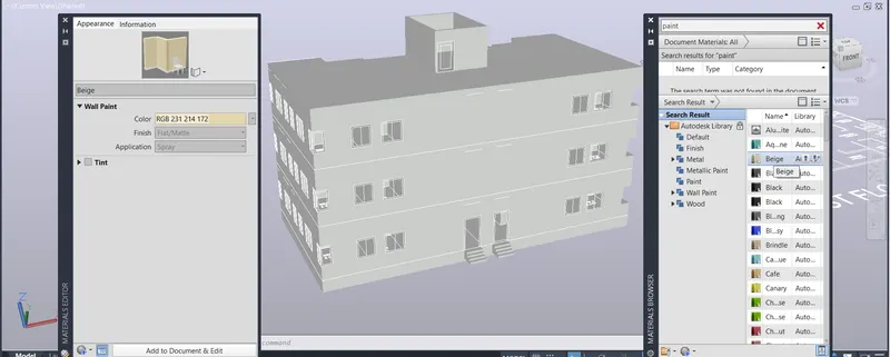
- So using these options we can assign the materials to our project in a very easy way as shown in the below figure:
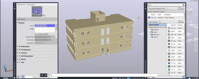
- Now after applying the material we have to render the project also.
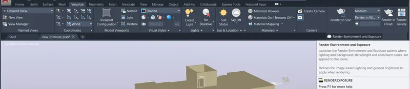
- So in order to render the project we first need to go to the VISUALIZE tab and then there will be another option named as Render Environment and exposure as shown in the below figure:
- Go to the Image based lightning option there we will be able to find the lot of options as we can see in the below image:
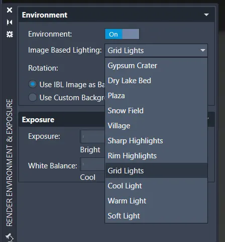
- Now the rendering has been complete.
FINAL RESULT: