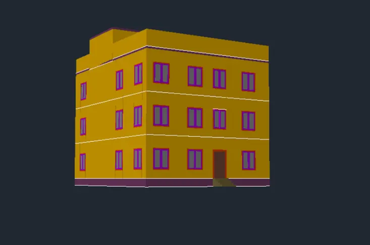
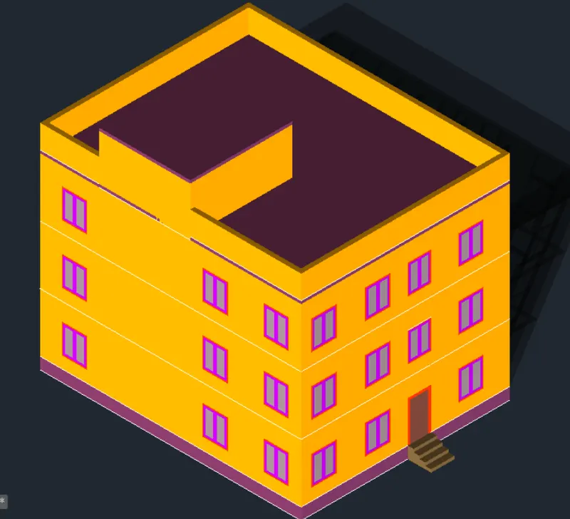
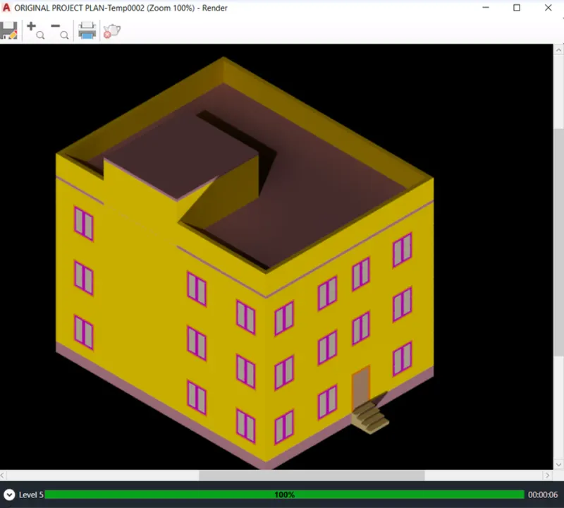
Project 2_Creating a 3D rendered model for a Residential Building in AutoCad
AIM:
To Create a 3D rendered model for a Residential Building in AutoCad
INTRODUCTION:
The main object of this project is to understand about to create a plan in 2D, then convert in into 3D using AutoCAD 3D, applying materials and rendering.
2D Tools:
- Line- Draw lines in AutoCAD.
- Polygon- Draws polygons with three or more sides.
- Rectangle- Used to draw rectangles.
- Circle- Command used to draw circles.
- Ellipse- Used to draw ellipse.
- Erase - Erase object in the drawing area.
- Copy- Used to copy one or more objects
- Mirror- Command used to mirror an exact duplicate of an object
- Offset- Used to offset one object from another a distance you specify
- Extend- Used to one line to another line
- Array- Use make a rectangular or ploar aray of an object
- Move- Used to move objects around in the drawing area
- Rotate- Used to Rotate an object around base point
- Scale- Command used to make an object larger or smaller
- Trim- Command used to trim an object from another object
- Chamfer- Used to put a chamfer between two lines
- Fillet- Used to fillet between two lines of a radius you specify
3D Tools:
Revolve
Draw>Modelling>Revlove
Extrude
Draw>Modelling>Extrude
This AutoCAD 3D Extrude command allows the user to create a 3D object by extruding a 2D face along a line or path.
Sweep
Draw>Modilling>Sweep
This command helps the user to extrude the 2D objects without the 2D face being orthogonal them into the beginning of the plan.
Union
Modify>Solids Editing>Union
This AutoCAD 3D command allows the user to combine two objects converting them into onle single object.
Subtract
Modify>Solid Editing>Subtract
This command is opposite to the union command.
Intersect
Modify>Soilid Editing>Intersect
With this AutoCAD 3D command, the user is left with the area that is comman to both the objects.
Rendering
Rendering is the process of creating a raster image based on the 3D objects in a same.
Applying Materials
- Click visualize tab Materials Browser. Find
- Select the objects wich you want to assign the material
- In the materials browser, right- click the material to assign and choose assign to selection.
PROCEDURE:
- Open Auto Cad
- In the right angle left corner click on the settings icon of workspace.
- Select 3d Modelling
- Enter UN (Units) command in the command box and change the type as decimal and select precision as 0.0
- Now enter Dim style in command box modify the settings and select primary units as decimal and give precisions as 0.0
- Select line command and draw in top or 2d mode
- Line command is used to draw the plan
- Command x line and draw line in x direction as well as in y direction
- Trim the unwanted lines
- Line command is used to draw the plan
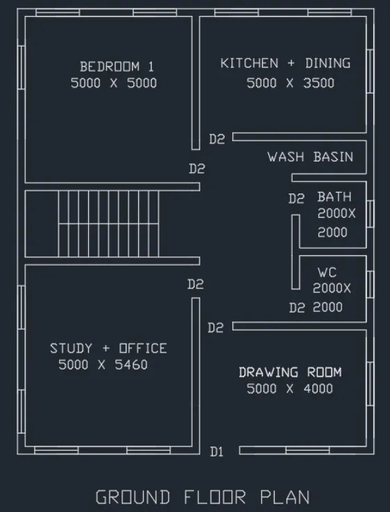
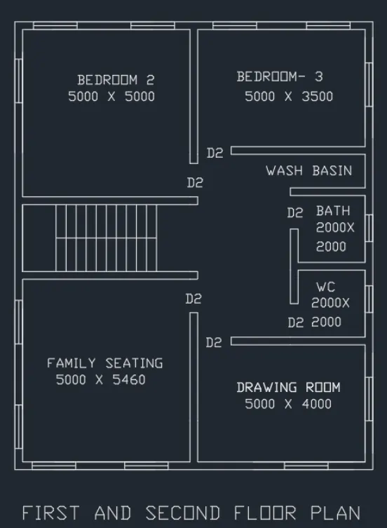
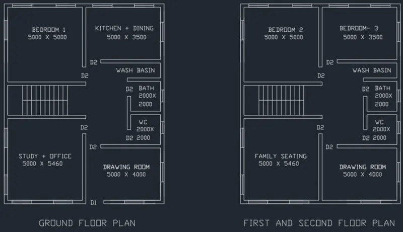
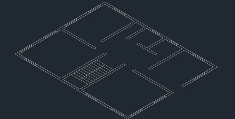
Procedure for creating the 3D plan
- In the right left corner click on the settings icon that is the icon of workspace
- Select 3D modeling
- Command boundary and in that select region
- Create boundarries as well as regions of the plan
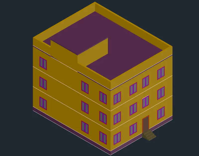
- Extrude the regions that are the walls to the height of 3000 from bottom
- Floor to floor height of the building is 3000
- Create differnt type of layers using layer properties like 3D Walls, windows frame, slab, doors ect...
- Assign colors to each layers separately
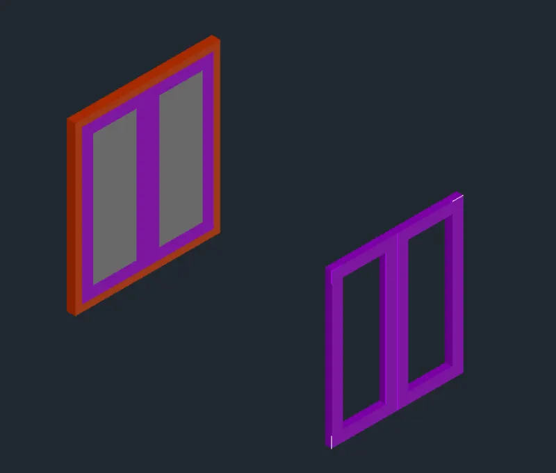
- Line command is used to draw the windows and doors
- Rotated 3D is used to rotate the objects as in window and doors
- Move and copy command is used to move the windows to their desired locations
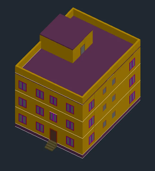
- Command polyline at the terrace and create the parapet wall at the top of the building
- Command polyline and create the plinth of the building of 600 at the bottom
- Create the staircase and extrude it to the distance of 1200
- Create the mumty separately and place it on the top of the building
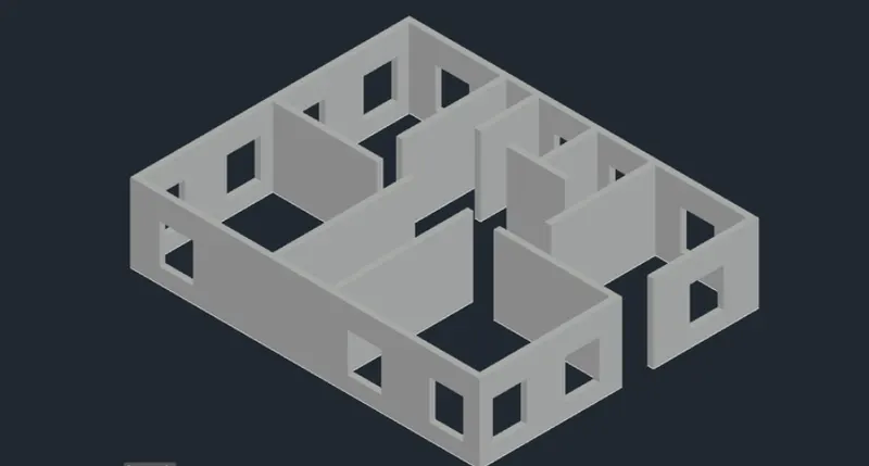
STEPS FOR RENDERING
- Go to the visualize tab from the fibbon
- This will give access to the panels like light, sunlight, camera, Animations, Render and Views
- Create differnt views using the camera and render the building
- Place the lights at desired locations