Creating a Floor plan, Footing detail and Isometric view using AutoCad
AIM:
To Creat a Floor plan, Footing detail and Isometric view using AutoCad.
Commands:
- Line (L)
- Rectangle (Rec)
- Trim (Tr)
Procedure:
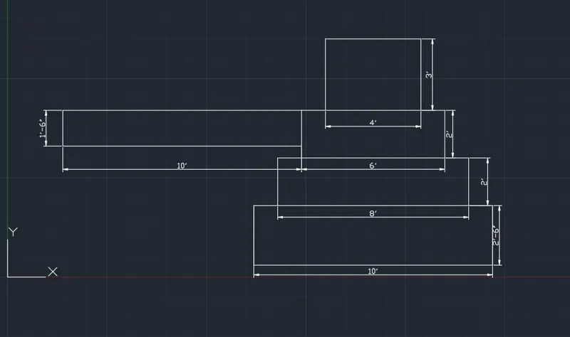
Step 1:
- Create a rectangle by command using Rec.
- First Point 6,6
- Length of Rectangle 10 feet
- Width of the Rectangle 2.5 feet
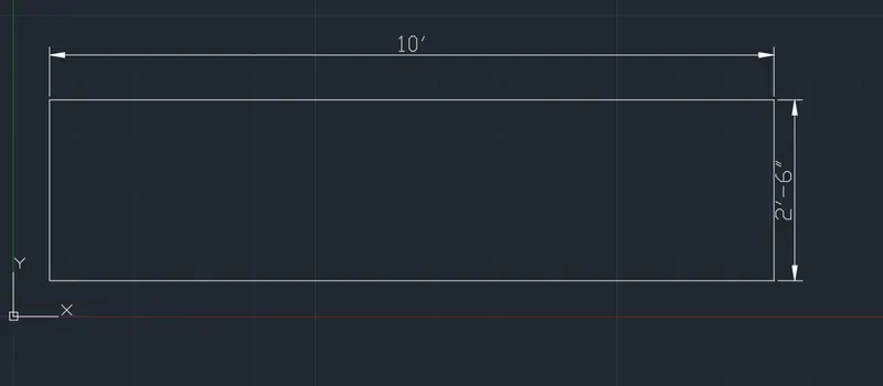
Step 2:
- Creat a next rectangle
- Size of 8 feet length and 2 feet width
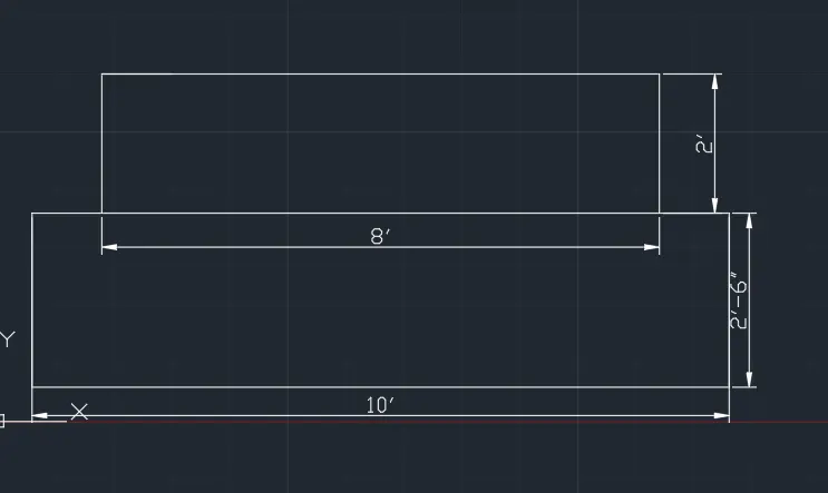
Step 3:
- Creat a next rectangle
- Size of 6 feet length and 2 feet width
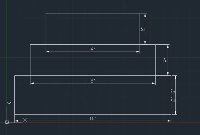
Step 4:
- Line draw the croner of last rectangle, by using the command of L
- Line length of 10 feet and with of 1.5 feet
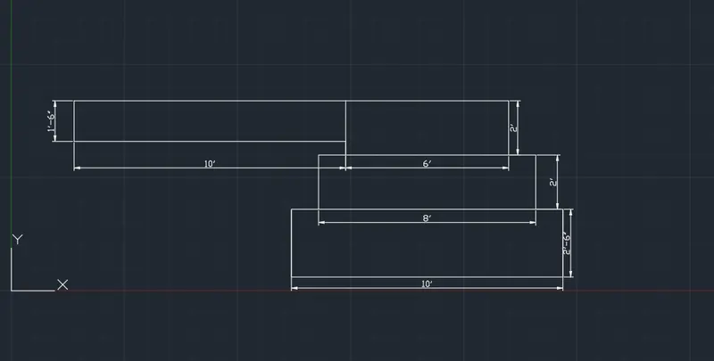
Step 5:
- Next rectangle drawn the centre of the previous rectangle.
- BY the size of 4 feet length and 3 feet width.
Step 6:
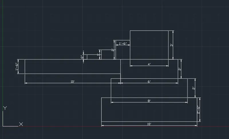
- Floor steps creat by using the command of L (line)
Step 7:
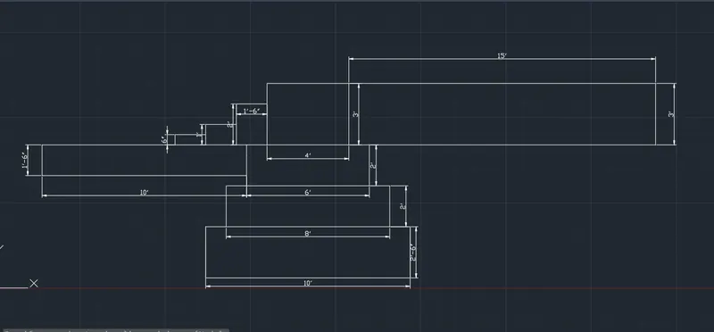
- Draw the floor by use the command of line.
Step 7:
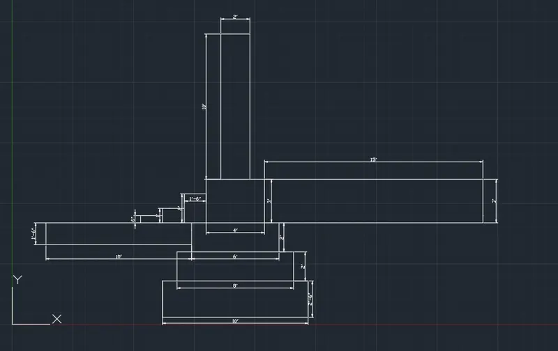
- Draw the wall to the base of footing with the thickness of 2 feet.
Result:
The cross section of load bearing wall over spread footing is drawn by using Autocadd software.
- AIM:
To Draw THE Isometric view of steps.
Commands:
- Line
- Isometric plane
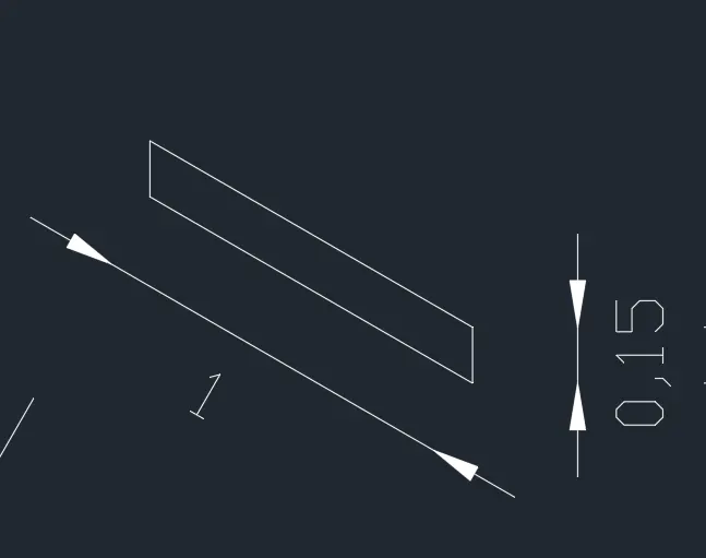
Step: 1
- X direction give 1 unit
- Y direction give 0.15
Step 2:
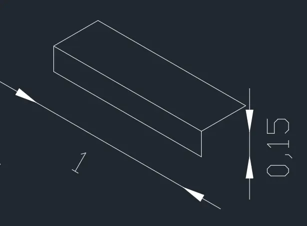
- 0.3 unit from last down points
- Move last to right direction 1 unit
- front give 0.3 unit
Step: 3
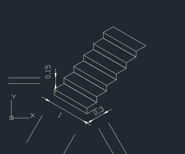
- Copy the right object ortho off
- Command co and specify the base point and place it at a new point.
- Repeat unit 5 steps are drawn.
Step 4:
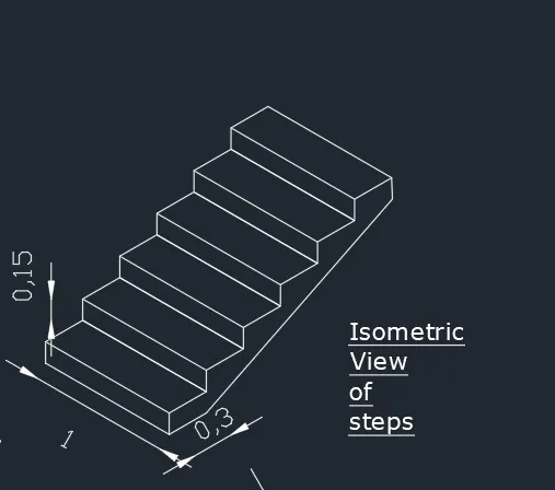
- With iso plane right to join the two ends with ortho off.
Result:
- The Isometric view steps are drawn by using Autocad software.