Project 2_Creating a 3D rendered model for a Residential Building in AutoCad
AIM: To create a 3D rendered model for a Residential Building in AutoCAD
Commands Used in this challenge
Line
Rectangle
Trim
Move
Copy
Explode
Circle
Dimlinear
Dimcontinue
Boundary
3Dorbit
3D rotate
Extrude
Region
UCS
Camera
Block
Render RR
Sweep
Create Light
Open AutoCAD
In Startup settings start from scratch select Imperial (Feet and Inches)
Open grid and snap settings
Change snap and grid spacing to 1’
Change major line every grid line to 10
Turnoff adaptive grid
Type ‘un’ in command box and press enter
Change units’ type to decimal and precision to 1’1/16” and insertion scale to inches
Change the workspace setting of AutoCAD from ‘drafting and annotation’ to ‘3D Modeling’
Step 1: Creating Layers
Open Layer properties and create new layers by clicking on new layer or right click on any layer and select new layer to create new
layer
Step 2: Creating Layers
Change the current layer to 3D_Wall
Create a rectangle of dimensions 10’9”X10’9” at any point on the screen
Offset the rectangle to inside to distance of 9” as wall thickness
Delete the left and bottom lines and extend them to the edges as shown in figure
Creating Views
Click on home button of the view cuble and zoom for better view
Go to visuvilise tab and click on new view
Set view name as VIEW 1
Click on current view and press ok
Click on the NE isometric view of the view cube and zoom for better view
Go to visuvilise tab and click on new view
Set view name as VIEW 2
Click on current view and press ok
Click on the Top view of the view cube and zoom for better view
Go to visuvilise tab and click on new view
Set view name as VIEW 3
Click on current view and press ok
Result:
Initially all the layers necessary are created with respective line types and line weights. Then plan view is drawn as shown in step 2.
Then from step 3 the 3D view is created with respective layers assigned. The UCS view is changed accordingly to make changes to
the 3D view and 3D dimensions.Boundary command is used for creating regions along the boundaries and extruding them. After this
view are created for showing result.The result consists of different views of the 3D model such as top view(View 3), SW isometric(View
1), NE isometric(View 2), Windows.
All dimensions are in Feet and Inches
Text and dimensions are added with respective layers
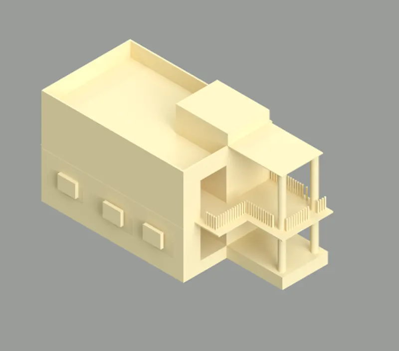
Render view
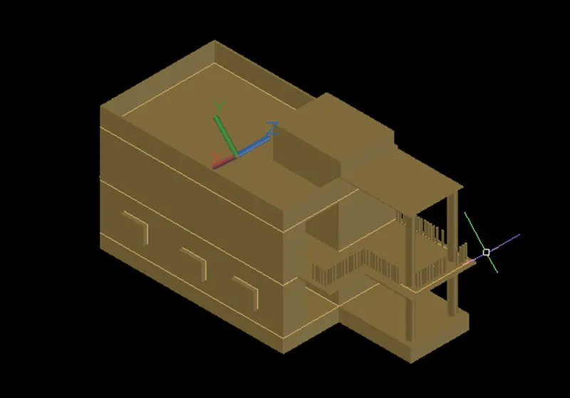
Realstic view
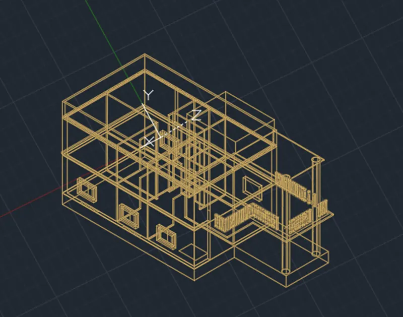
2d wire frame