Creating a Floor plan, Footing detail and Isometric view using AutoCad
Aim-Creating a Floor plan, Footing detail and Isometric view using AutoCad.
PROCEDURE:
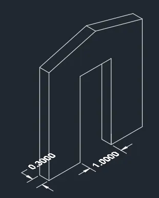
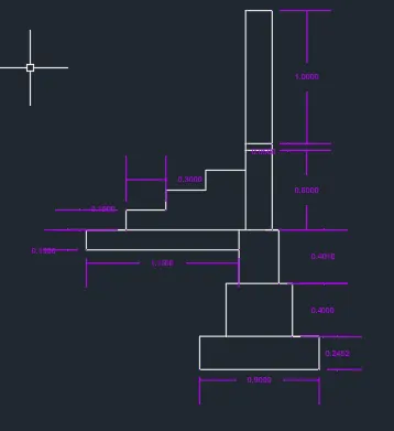
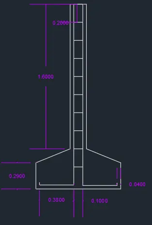
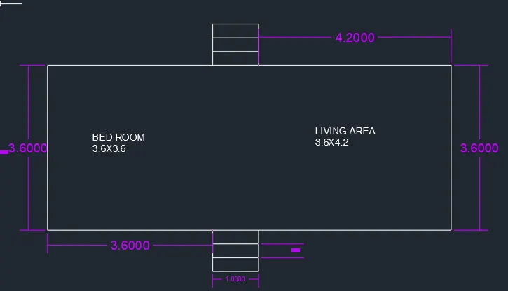
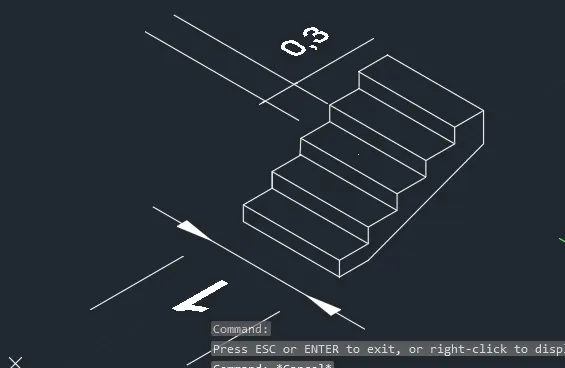
1. Type „U‟ ◄┘ (enter) and set up the units in meters.
2. Type „L‟ ◄┘ give the dimensions for line as 5.0 ◄┘ and indicate the direction of line if ortho is
ON
3. Proceed the above procedure for all the walls.
4. By typing „O‟◄┘give offset distance as ◄┘ for external LINE and ◄┘for internal LINE
5. Type „Tr‟ double enter ◄┘◄┘for trim command then trim the extra and unnecessary lines.
6. By typing A ◄┘ give arc command to indicate or give doors.
7. Type DLI ◄┘ to give the dimensions for the plan.
8. Type DT ◄┘ to give text in each part of the plan.
9. Using the above commands section and elevation is also drawn by following same procedure.
10. Type „H‟ ◄┘ for batch command and indicate the cross section and indicate brick work,
concrete and sand filling etc.,
11. Thus by following above steps required plan is obtained.
RESULT: The given plan, section and elevation of a single storeyed building is drawn as per
specifications using software AUTOCAD.