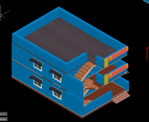
Project 2_Creating a 3D rendered model for a Residential Building in AutoCad
1.
Aim: To create a 3D rendered model for a residential building in AUTOCAD
Commands used:
LINE, OFFSET, PLINE, TRIM, RECTANGLE
commands are used to draw the plan and Windows with its dimensions in 3D modelling
1. REGION is used to create the region of the plan walls
2. REGION is used to create the region of the Floor
3. BOUNDARY is used to create the boundary of the region created by picking the points.
4. EXTRUDE is used to extrude the walls created as a boundary to a height of 12'
5. EXTRUDE is used to extrude the Floor created as a boundary to a height of 150mm
6. EXTRUDE is used to extrude the Ceiling created as a boundary to a height of 150mm
7. LAYER is used to crate the layer of different components like 3D Wall, 3D Window,3D window mullion, 3D Glass etc
8. 3D ORBIT is used to see the 3D plan in the desired direction
9. SLICE is used to cut the model using the 3points with desired axis
10. 3D ROTATE is used to rotate the window created in the xz plane to xy plane
11. EXTRUDE is used to extrude the window created as a boundary to a height of 15"
12. EXTRUDE is used to extrude the window glass created as a boundary to a height of 9"
13. MATERIAL BROWSER is used to browse the appropriate materials to different components and assign it to create a rendering view
14. RENDER TO SIZE is use to select the quality of the rendering view and selecting FULL HD resolution 1920X1080p
Procedure:
1. Open AutoCad set UN(units) and selecting Engineering feets and inches
2. Using command line draw a line 40' and length 60' ( 40' X 60')
3. Offset the line by using the offset command 15"
4. Next trim the unwanted lines
5. With the help of the line command draw the rooms kitchen , living room , bedroom that the dimensions are mentioned in the diagram .
6. Draw the doors and windows and trim the unwanted menbers
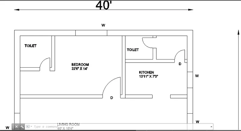
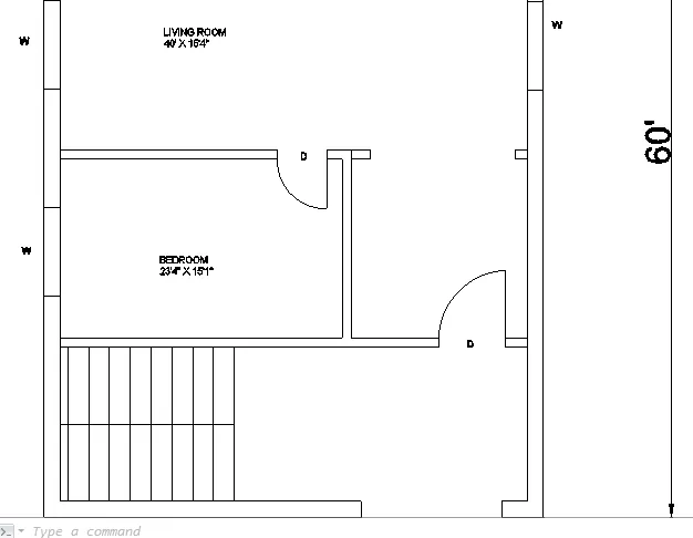
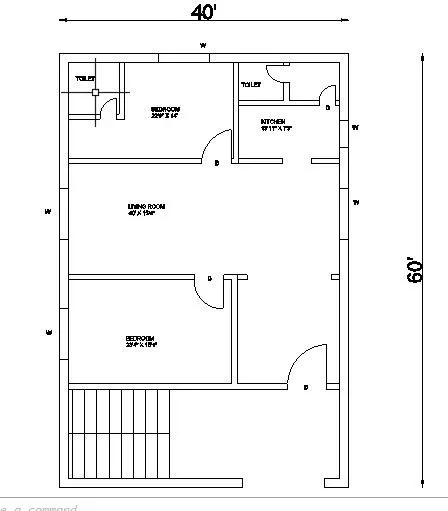
Step by Step Procedure by Picture
Step 1: Create a Plinth level by using Region and Boundary
Step 2: Creating a wall extrude wall from plinth level to 12'
Step 3: Creating Wall with opening of Window and Door
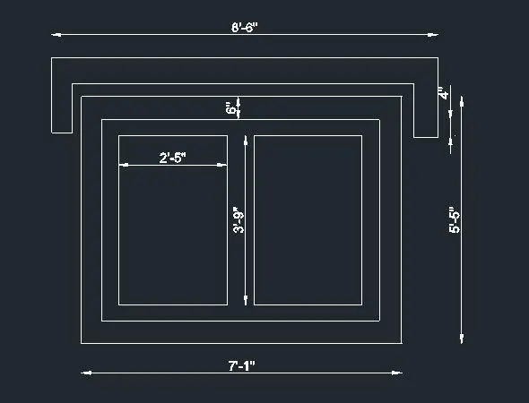
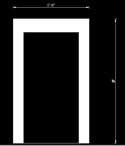
Step 4: Creating Window and Door and placing it in a place
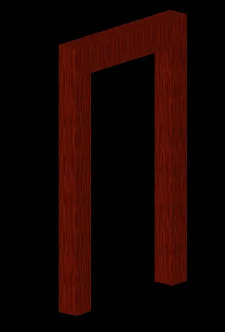
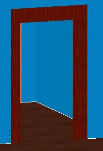
Step 5: Placing Walls, Door and Windows all together
Step 6: Diagram of Window, Doors
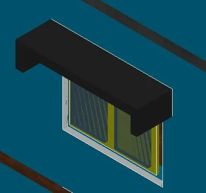
Step7: Placing Ceiling over the Ground
Step 8: Creating the Same that is created in Ground Floor to the First Floor
Step 9: Creating the Ceiling of the First Floor and creating the Parapet Wall
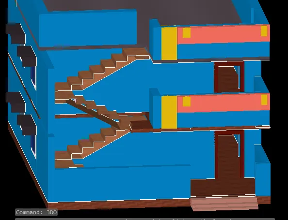
Step 10: Creating the Stairs and Balcony on the First Floor
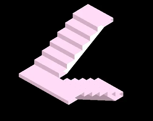
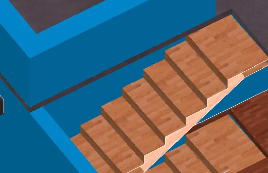
Step 11: The Image after assigning the Materials to the to the different components
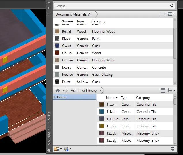
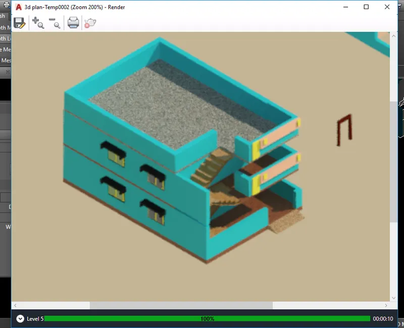
STEP 12: The environment condition in rendered view
Result:
Rendered Image of the 3D modelled Building: