Creating a Floor plan, Footing detail and Isometric view using AutoCad
1.
Creating a floor plan , footing detail and isometric view
Based upon the footing i created the load bearing which is above the plinth beam it is in between the columns
coming to the load bearing wall
AIM: To draw the cross section of load bearing wall in 2D using autocad software
Commands i used
Line tool , rectangle , trim
Procedure:
- Creating a rectangle i use the RECT option In command box first corner points (5,5) length is 0.9 and width is 0.25 ( NOTE : units in Decimal)
- After creating the rectangle again i want to create another rectangle on above of the first rectangle corner point 0.2from starting point and its dimensions is length is 0.5 and width 0.4
- Simillarly create a third rectangle from the first corner point which is 0.05 from start point of second rectangle dimensions length 0.4 and width 0.4
- Line is drawn form the crorner of the third rectangle and line length is 1.15 drawn to left side and downwards 0.15
- Simillarly line is drawn from the corner of the second rectangle and length is 1.15 to the left side and downwards 0.15
- Create a steps from the second rectangle dimensions vertically 0.15 and horizantally 0.30 upto three steps
- Draw another rectangle above the 4th rectangle dimensions is length is 0.3 and width 0.05
- Draw the 5th rectangle and its dimensions length 0.3 and width 1
- Trim the unwanted lines
Result
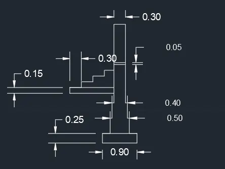
Cross section of Isolated footing
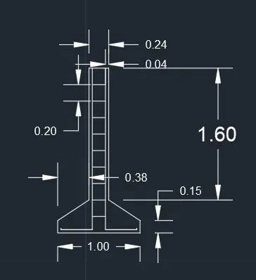
AIM: To draw the isolated footing
Commands:
line , off set , trim
PROCEDURE:
Draw aline command L and give units 1
1. Specify the start point and end point of the line segment by clicking in the drawing area length is 1
- Given relative coordinate as 0,0.15 Using command Line
- next coordinate 0,1.6
- Give 0.28,0
- Next coordinate 0,-1.6
- next coordinate 0.38,-0.25
- next 0, -0.15
2.Draw the oof setd distance 0.04 from bottom of the line to upwards
- Command "o" slelect the object and crate a offsets distance 0.04
- same applicable to right and left bottom end
- trim the unwanted lines
3.Again the same command offsets from the topline distance 0.2
Result
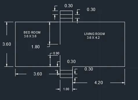
2D Line diagram of a two bedroom building by using line command
AIM: To draw a line diagram of 2 bedroom building
COMMANDS
Line , Rectangle , Offsets , Trim
PROCEDURE:
1. Create a bed room 8.2x3.6 by using rectangle
2. Draw a offset at a distamce 4.2 from right bottom end and left bottom end 3.6
3.Extend two lines in top and bottom distance 0.3 and repeat the same and create two off sets
4. Using line command draw a line distace 3.2 from left bottom and end upwards 0.9 , downwards 1.8
Result
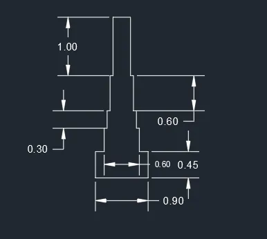
Load bearing wall showing foundation details
AIM: To fraw cross section of load bearing wall showing foundation details
COMMANDS:
Line , Rectangle , Trim
PROCEDURE:
1. Create a rectangle using command box and specify first corner point 5,5 and length 0.9 width 0.45
2. Create another rectangle first corner point 0.15 from the staring point of first rectangle and enter length 0.6 width 0.4
3. Create third rectangle from the first corner point is 0.05 from the staring point of the second rectangle length 0.5 and width 0.3
4. same as above points create a fourth rectangle first corner point is 0.05 from the starting point of second rectangle length is 0.4 and width 0.6
5. coming to the fifth rectangle corner point of the fourth rectangle and the dimensions length as 0.3 width as 1
6. Trim the unwanted lines
Results
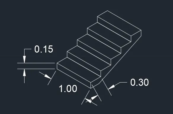
Isometric view of steps
AIM: TO draw the isometric view of steps
COMMANDS:
Line , Isometric plane
PROCEDURE:
1. While we work with isometric view command ds , snapoff , grid off put isometric snap on . Make ortho mode is on
2. From isometric drafting select iso plane left moving the cursor to y direction top 0.5 same as in x direction 1 and to y direction downwards -0.15
3. Change isometric drafting to iso plane top move the cursor back and give 0.3 from last drawn point and to right direction give 1unitfrom front 0.3
4. Change drafting to right ortho off and copy the element and select the base point and place new point until 4 steps formed
5. With iso plane right join the two ends
Result:
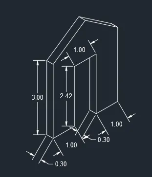
Isometric view of gable wall
AIM:To draw the isometric view of gable wall
COMMANDS:
Line , ISometric plane
PROCEDURE:
1. While we work with isometric view command ds , snapoff , grid off put isometric snap on . Make ortho mode is on
2. From isomteric drafting iso plane left moving the cursor to right give 1 unit and upwards 3
3. Draw 0.3 units to left and 3 units downwards and 0.3 units to left
4. Using isometric right take line command and draw upward 2.42 from the staring point
5. Draw 1 unit towards the right and 2.42 units downwards
6. Using isometric left again and draw 0.3 to left side and draw a line which intersects the top line
7. Using isometric right draw 1 to right side 3 upwards
8. Using the line command from bottom left corner 1.5 and extend line 4 upwards total 3.25 from bottom
9. Draw it to the other side slso it meets the right corner
10. Draw the vertical line with ortho on 0.3 and join the vertical using left and right same as above point and trim the unwanted lines
Results: