Creation of geometries by Coordinate system methods using AutoCad
1.
AIM:
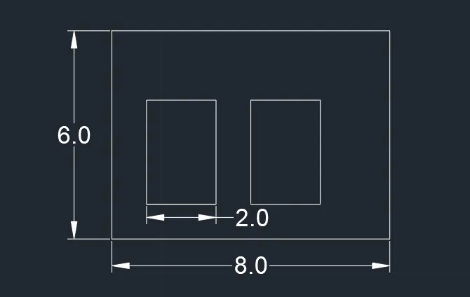
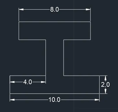
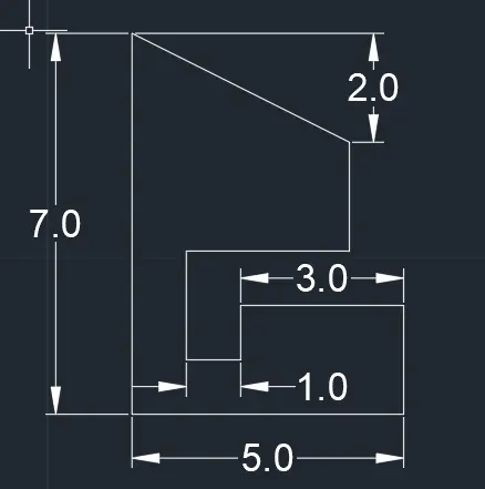
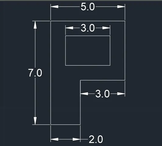
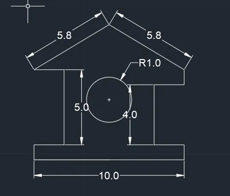
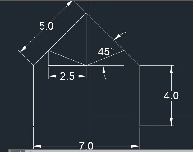
Using the AUTOCAD software he geometries from P1 to P2 using all the coordinates system methods.
By using the Line tool to create the geometries. Where required you need to use the circle tool.
INTRODUCTION:
With the help of AUTOCAD software i drawn the diagrams that give in the questions by using coordinste system method.
In the given questions the dimensions are given i mentioned the dimensions in autocad i calculated the dimenions by coordinate system method and gird format method.
- specify the start point and end point of the line segment by clicking in the drawing area specific dimensions.
- Continue specifying additional line segments and draw a line.
To undo the previous line segment, enter u at the prompt. Click Undo on the Quick Access toolbar to cancel the entire series of line segments:
- Press Enter or Esc when done or enter c to close a series of line segments.
This procedure is similar to all diagrams in some diagrams we use circle and angles
- Specify the start point.
- Enter the left angle bracket (<) and the angle, for example <45, and move the cursor to indicate the direction.
- Move the cursor to indicate the approximate angle.
- Specify the second point.
- Press the Spacebar or Enter.
1.
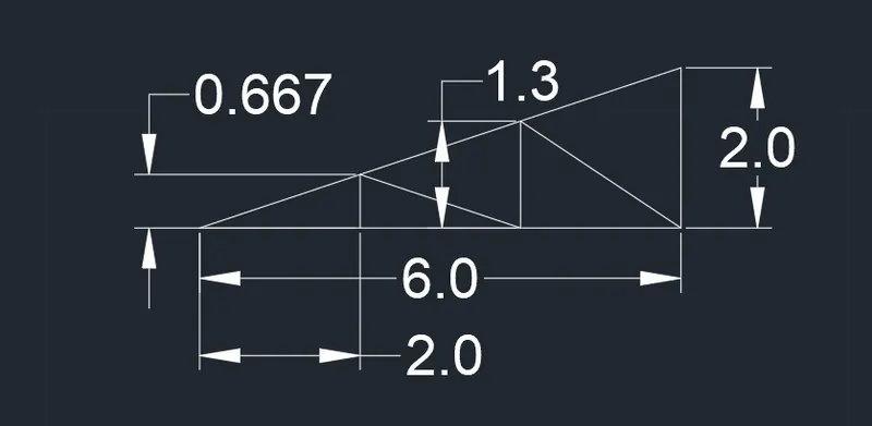
Coming to the First diagram P 1 for example
we start the points from X axis and y axis actually the facings are east 0`degrees` north 90 , west 180 , south 270 degress by using this facings of angles we drawn the diagram.
Simillarlly same all applicable to other diagrams also
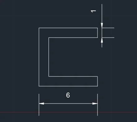
2.
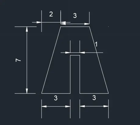
3.

4.
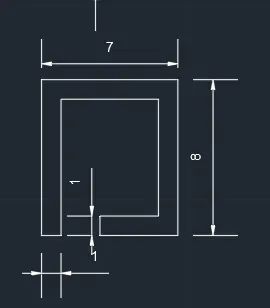
5.
6.
7.
8.
9.
10.
11.