Project 2_Analyze and Design the RC office building as per IS standard code in TEKLA STRUCTURAL DESIGNER
Question. Develop general arrangement for the RC office building. Analyze and design the building as per IS standard code in TEKLA STRUCTURAL DESIGNER. Refer the attached plan and elevation. The building to be designed for dead, live, wind and seismic loading.
Report of each member to be generated and extract drawings for structural plans, beam reinforcement details from the software.
Solution.
AIM:- To develop general arrangement for the RC office building. Also, to analyze and design the building as per IS standard code in TSD software from the attachment. Also, to generate report of each member and extract drawings for structural plans, beam reinforcement details from the software.
PROCEDURE:-
- The very first step in order to develop a general arrangement of the RC office building. First, open the TSD software.
- Then go to the home tab, in that tab there will be an option named as the Settings just click on that option just as shown in the below given image:

- Then there will be a dialouge box named as the Settings and in that dialouge box set to Indian Standard code and set the design code just as shown in the below given image:
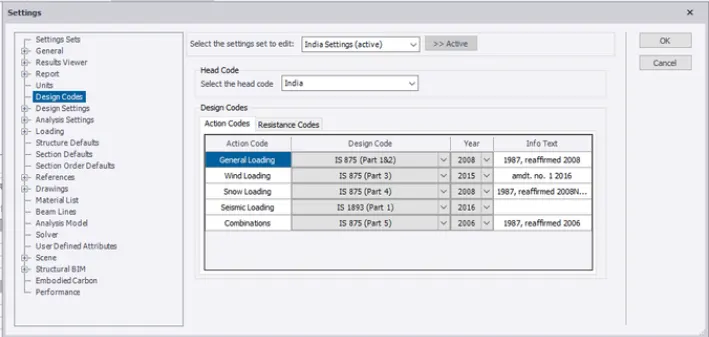
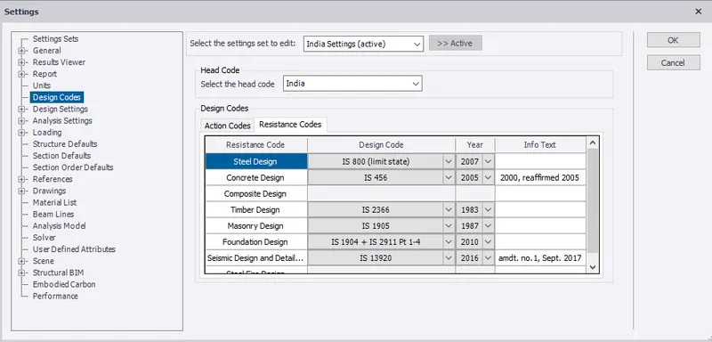
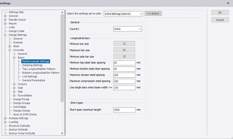
- Next step is to set the reinforcement settings for concrete beam just as shown in the below given image:
- Next set the top longitudinal bar pattern details for continuous beam and the cantilever beam just as shown in the below given image:
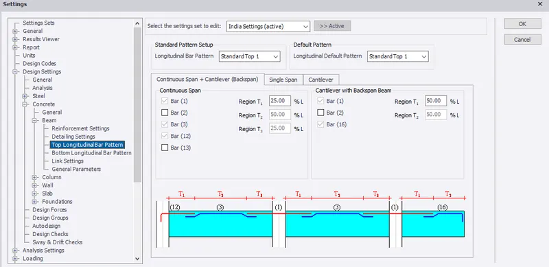
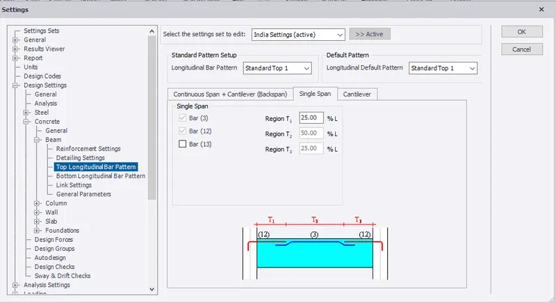
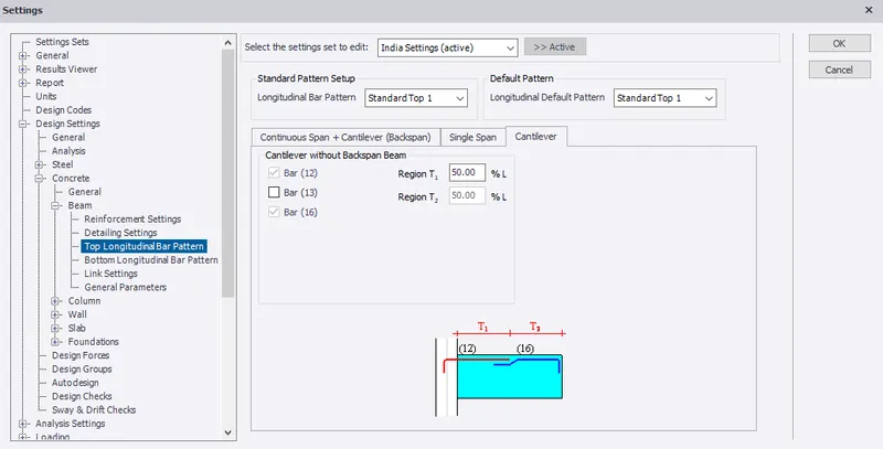
- Now next we will be setting the top longitudinal bar pattern details for single and the cantilever beam just as shown in the below given image:
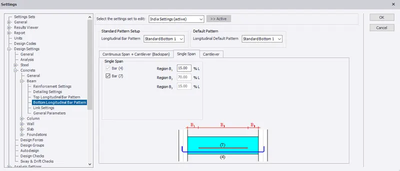
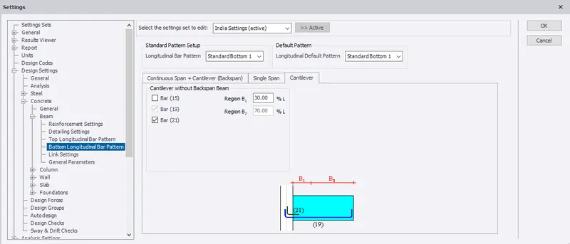
- Similarly, set the bottom longitudinal bar pattern details for single and the cantilever beam just as shown in the below given image:
- Now, we will be setting the link bars for the shear design in beam just as shown in the b elow given image:

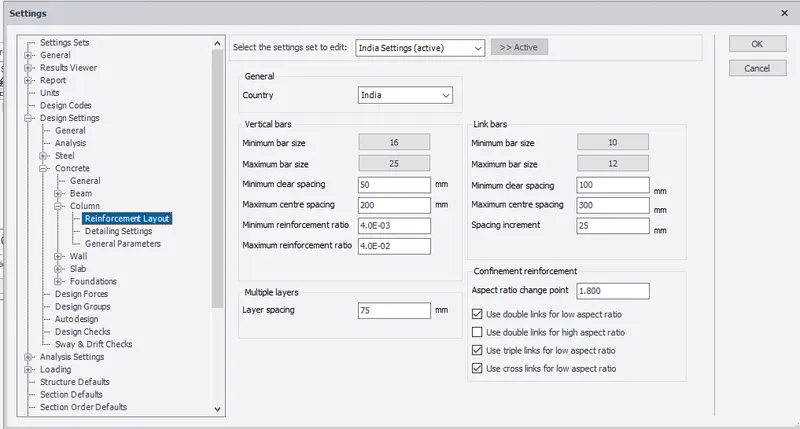
- And then set the reinforcement layout for column just as shown in the below given image:
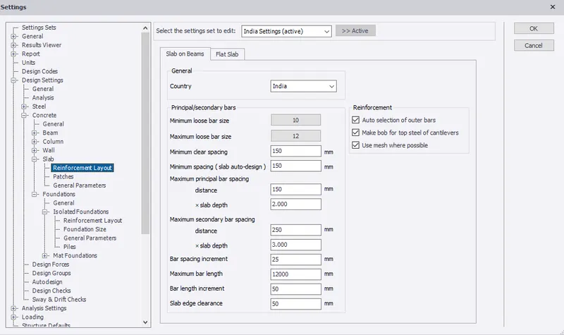
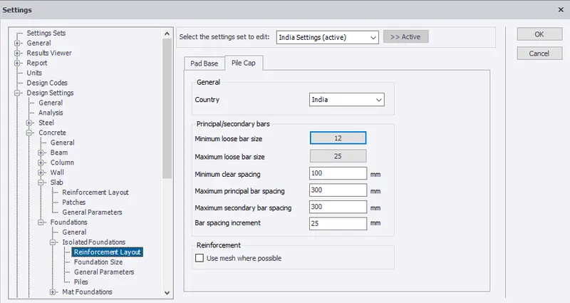
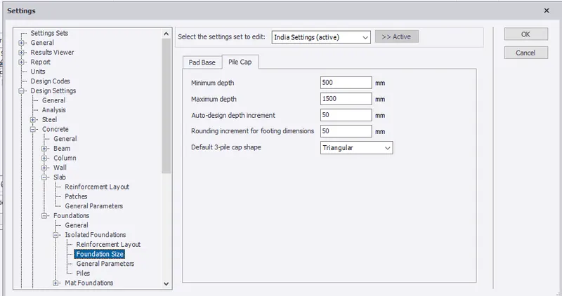
- Similarly, set the other parameters for slab on beam just as shown in the below given image:
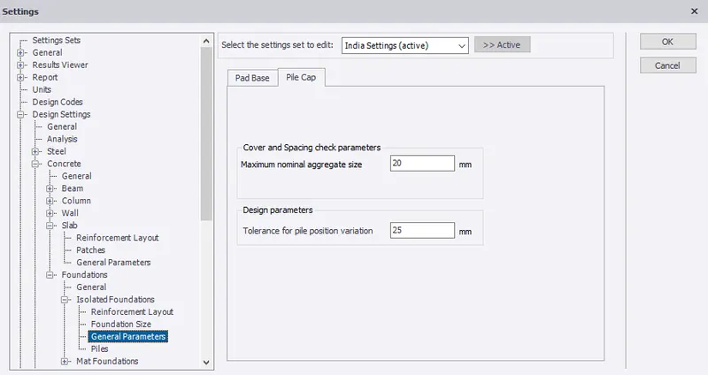
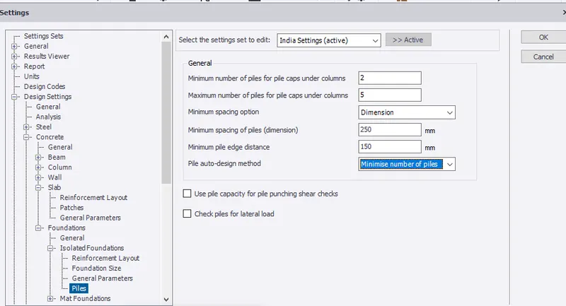
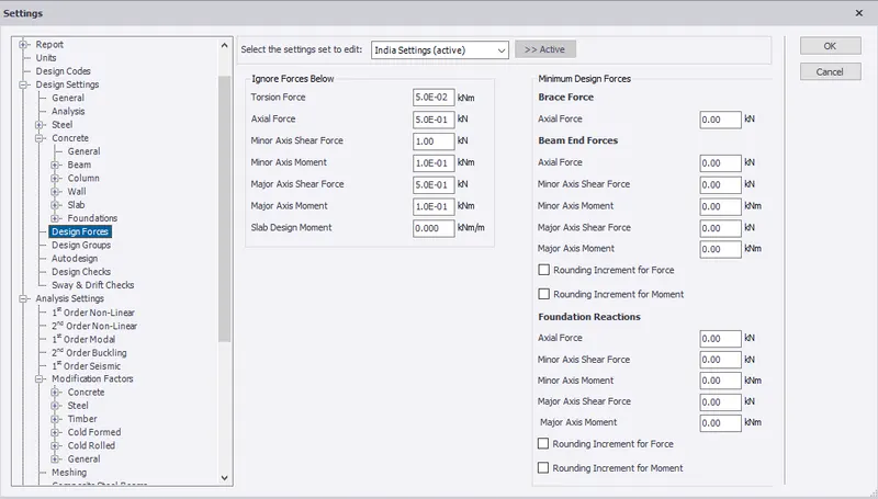
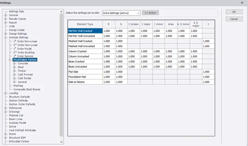
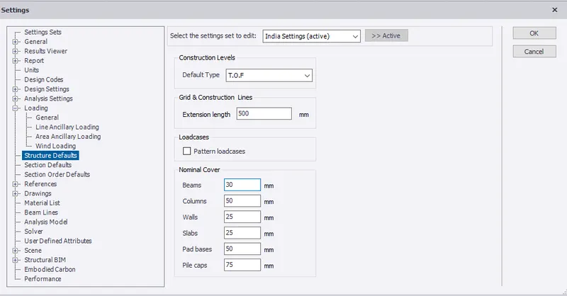
MODELLING:
Construction Level and grid line:
- Next we will be modelling the levels and the grid lines.
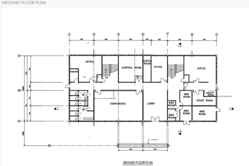
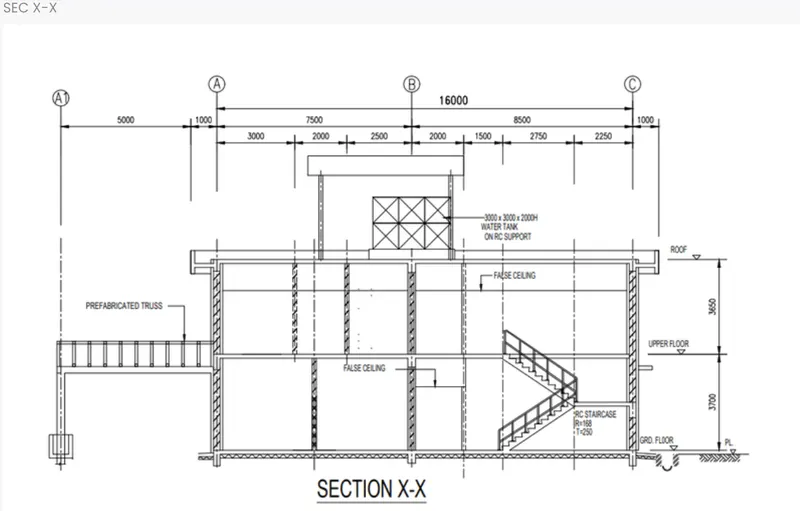
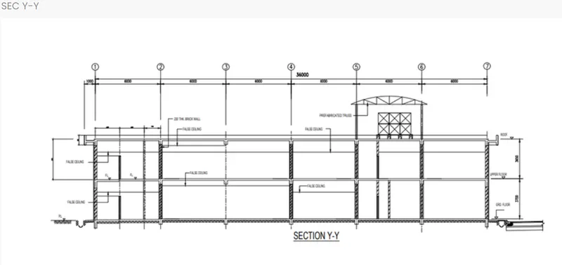
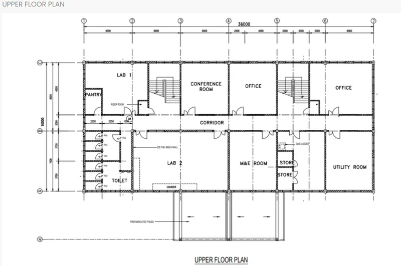
- So in order to draw the levels and the grid lines refer the plan and section drawings which is provided in the assignment just as shown in the below given image:
Ground Floor plan:
Section X-X:
Section Y-Y:
Upper Floor Plan:
Construction Level:
- First we will be creating the construction level. And in order to assign the Construction level go to the Model tha and in that tab there will be an option named as the Construction Level just click on that option as we can see in the below given image:

- Then there will be a dialouge box named as the Construction level, and in that dialouge box create the levels according to the sections given in the assignment, so create the construction level just as shown in the below given image:
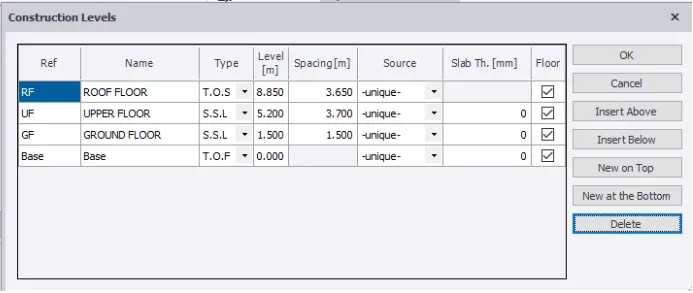
- The construction levels have been created in the Construction level dialouge box and now we will be creating the grid lines.
Grid Lines:
- Next we will be creating the grid lines and in order to create the grid lines go to the model tab and in that tab there will be an option named as the Grids just select that option just as shown in the below given image:

- Next, add the grid line by picking the points on the scene view in the base level just as shown in the below given image:
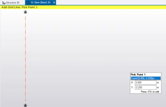
- Next select the reference line to add quick parallel line by specifying the distance just as shown in the below given image:
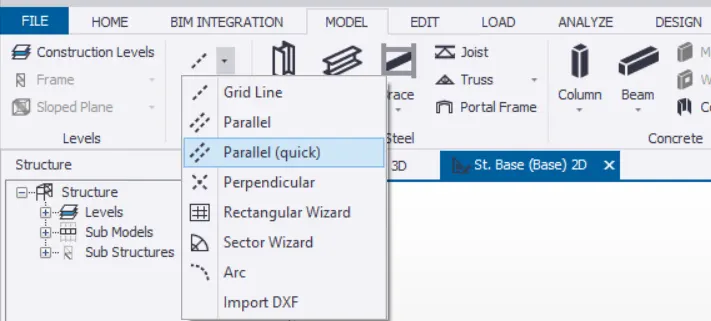
- Next draw the remaining grid lines using the quick parallel line options just as shown in the below given image:
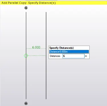
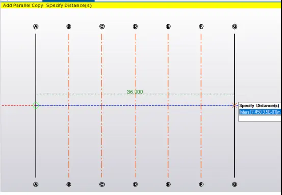
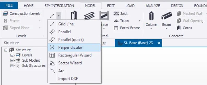
- Next we will be adding the horizontal grid lines so in oder to add the horizontal grid lines go to the Model ribbon tab there will be an option named as the Perpendicular just click on that option just as shown in the below given image:
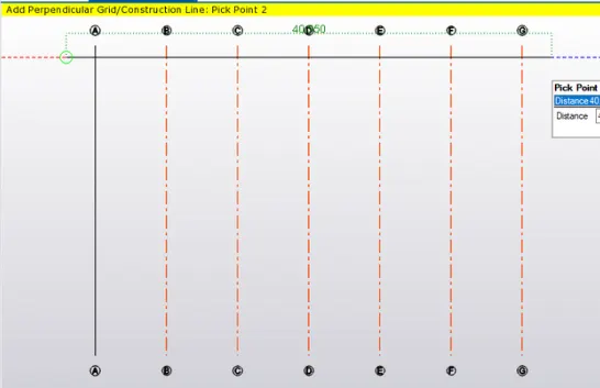
- Next draw the perpendicular grid line by specifying the reference line and point of intersection just as shown in the below given image:
- Do the same procedure to create the rest of the grid line just as shown in the below given image:
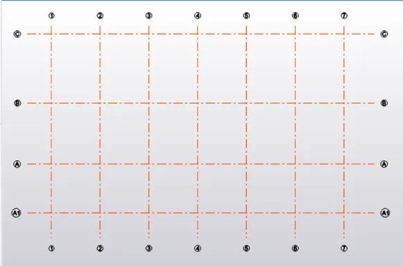
Concrete Column:
- Now next we will be designing the concrete columns and in order to create the concrete column we need to go to Manage Property Sets under the Home ribbon tab just click on that option just as shown in the below given image:

- After that there will be another dialouge box named as the Manage Property Sets and in that dialouge box there will be an option named as the New just click on that option then there will be a drop-down list and in that list there will be an option named as the Members click on that after that there will be another drop-down list and in that list there will be another option named as the Concrete column click on that option as well just as shown in the below given image:
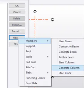
- After that in that dialouge box select the concrete column from members, set 400mm X 400mm concrete column with M30 grade concrete.
- Set nominal cover as 40mm and releases as fixed just as shown in the below given image:
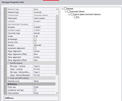
- Next go to the Model ribbon tab then there will be an option in that tab named as the Column click on that option just as shown in the below given image:

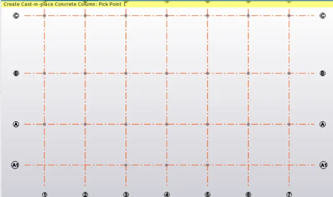
- Now select C1 from property window and set from base level to roof floor level, and then pick points to create concrete columns just as shown in the below given image:
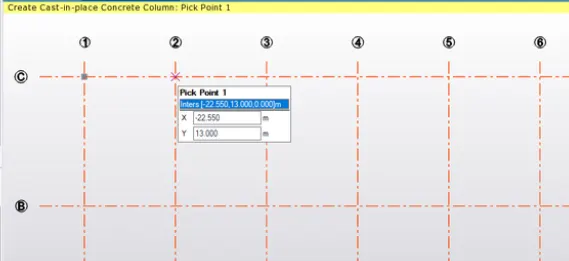
- Now do the same procedure as we have done in the previous step and place the concrete column at their respective places just as shown in the below given image:
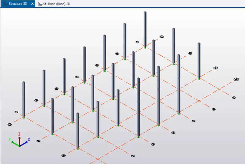
3D-VIEW:
Concrete beam:
- Next we will be designing the concrete beam and in order to design the beam go to the Home Ribbon tab then there will be an option named as the Manage Property Sets just click on that option just as shown in the below given image:
- After that there will be another dialouge box named as the Manage Property Sets and in that dialouge box there will be an option named as the New just click on that option then there will be a drop-down list and in that list there will be an option named as the Members click on that after that there will be another drop-down list and in that list there will be another option named as the Concrete beam click on that option as well just as shown in the below given image:
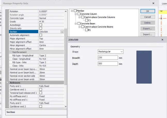
- Next select the concrete beam from members, set 230mm x 500mm concrete beam with M30 grade concrete.
- Set nominal cover as 30mm and releases as fully fixed just as we can see in the below given image:
Ground floor:
- After this go to ground floor in the scene view and then go to the Model ribbon tab click on that option then there will be an option named as the beam just click on that as well just as shown in the below given image:

- Now select B1 from property window and set to simply supported beam and pick points to create the concrete beam just as shown in the below given image:
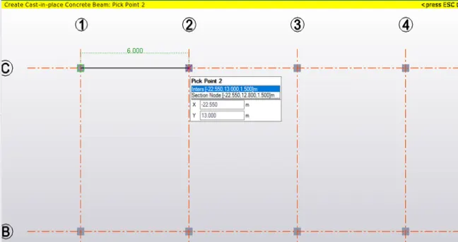
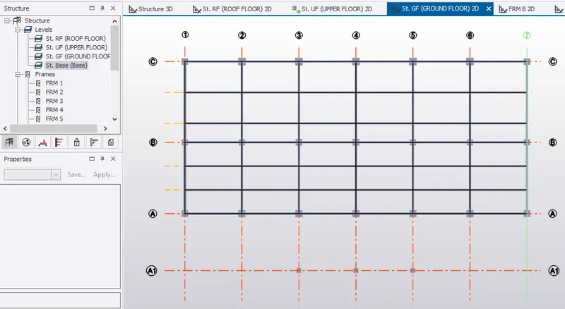
- Similarly, create the concrete beam till gridline 7 just as we can see in the below given image:

- Now for the other beams on the gridlines either do the same procedure as above or just copy the beam created to grid line B and A just by picking the reference node just as we can see in the below given image:
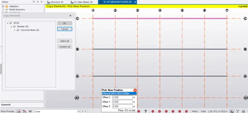
- Similarly, create and copy vertical beams just as we can see in the below given image:
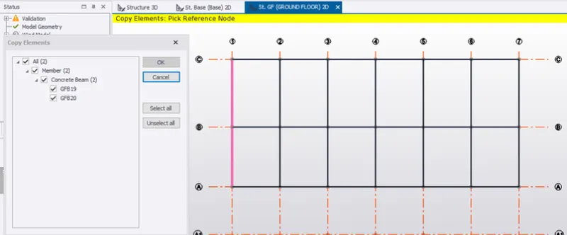
- Since the span size of the primary beams are large, ie, 8.5m and 7.5m so, select the quick parallel construction line by selecting the reference line create the construction line slightly away from the grid line 4,A and B respectively, just as we can see in the below given image:
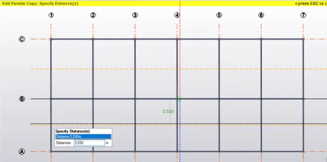
- Again using the copy command, copy the beam B1 from gridline C to newly constructed line just as shown in the below given image:
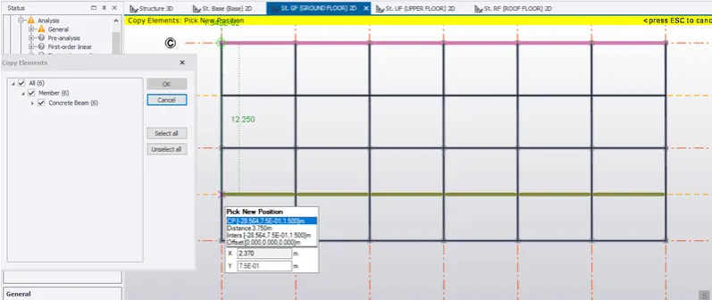
- Below is the image after contructing all the concrete beams in the ground floor:
First floor:
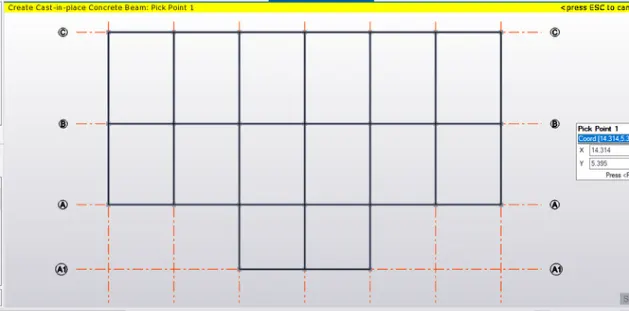
- Next go to the upper gloor i.e; first floor in the scene view.Select concrete beam from Model tab.Select B1 from property window and set to simply supported beam.Pick points in order to create concrete beam.Create concrete beam for gridline A,B and C as we can see in the below given image:
- Next step is to validate the model.And in order to validate the model go to the Model ribbon tab there will be an option named as the Validate just click on that option just as shown in the below given image:

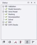
- So after validating the structure we can see that there are no errors so we can proceed further just as we can see in the below given image:
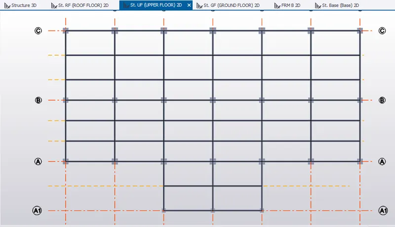
- As we can clearly see that the span size of the beam is large, more than 7.5m and 8.5m then we will be providing the secondary beams in between.
- And in order to design the secondary beam we will be copying the beam elements.
- So, copy beam B1 as secondary beam at 4.25m from gridline C and 3.75m from gridline B just as we can see in the below given image:
Roof Floor:
- Do the same procedure for the roof floor also just go to roof floor in the scene view.Select concrete beam from Model tab.Then select B1 from property window and set to simply supported beam.Pick points to create concrete beam.
- And create concrete beam for gridline C,B and A just as shown in the below given image:
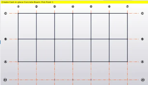
Cantilever concrete Beam for Roof Floor:
- In order to modelling the cantilivere concrete beam, go to the Home Ribbon tab then there will be an option named as the Manage Property Sets just click on that option just as shown in the below given image:
- Set nominal cover as 30mm and releases as fully fixed at one end and cantilever at other end just as shown in the below given image:
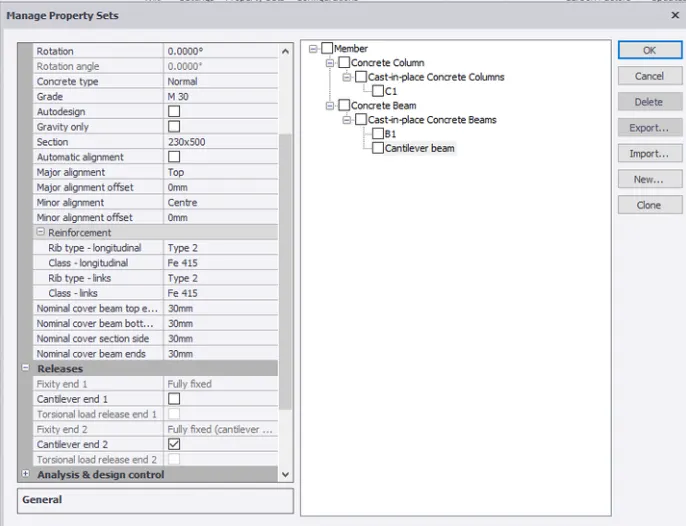
- After this go to ground floor in the scene view and then go to the Model ribbon tab click on that option then there will be an option named as the beam just click on that as well just as shown in the below given image:
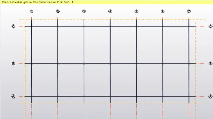
- Now select B1 from property window and set to simply supported beam and pick points to create the concrete beam. Go to roof floor in the scene view.Select concrete beam from Model tab.Select cantilever from property window. Pick points to create cantilever beam as shown below.
- Provide simply supported beam at the cantilever ends at 1.5m from gridline.Therefore, cantilever slabs are provided just as shown in the below given image:
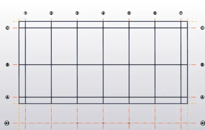
- Next, provide the secondary beams,B1 as we had provided for upper floor just as shown in the below given image:
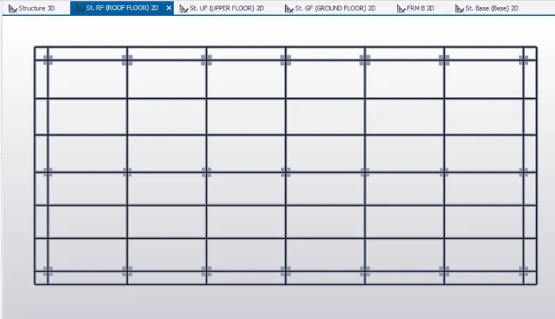
3D-VIEW:
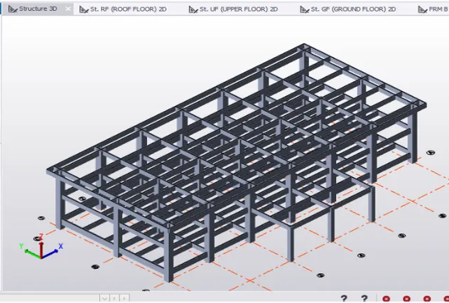
Concrete Slab:
- Next we will be designing the concrete slab and in order to design the slab go to the Home Ribbon tab then there will be an option named as the Manage Property Sets just click on that option just as shown in the below given image:
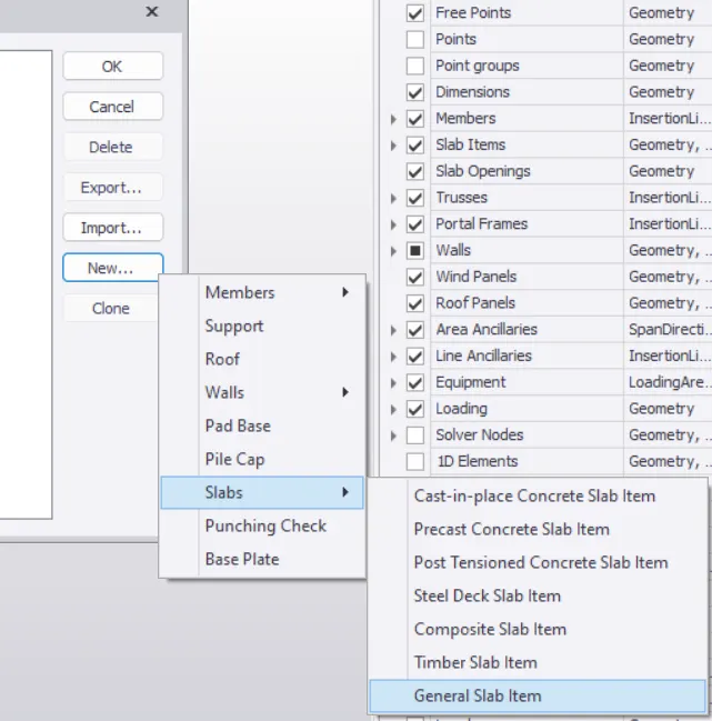
- After that there will be another dialouge box named as the Manage Property Sets and in that dialouge box there will be an option named as the New just click on that option then there will be a drop-down list and in that list there will be an option named as the Slabs click on that after that there will be another drop-down list and in that list there will be another option named as the General Slab Items click on that option as well just as shown in the below given image:
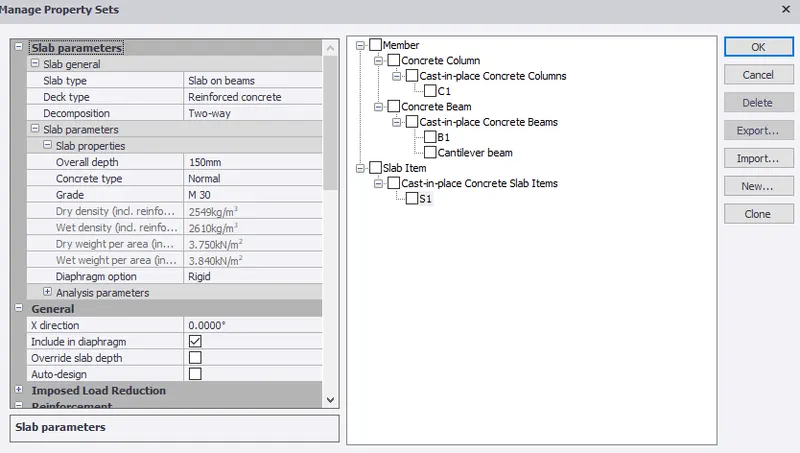
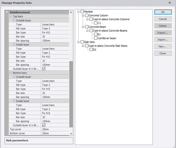
- Next, set the slab properties as the two-way slab type as slab on beams with M30 grade concrete and overall depth 150mm. Set cover as 25mm and provide 10mm diameter bars at 150mm c/c spacing just as we can see in the below given image:
- Go to upper floor in the scene view.Select slab on beam from Model tab just as we can see in the below given image:

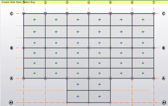
- Select S1 from property window. Create slab item by selecting bay just as we can see in the below given image:
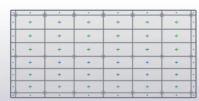
- Similarly, go to roof floor in the scene view.Select slab on beam from Model tab.Select S1 from property window. Create slab item by selecting bay just as we can see in the below given image:
LOADING:
Manual Calculations of Dead Loads:
1- Dead Loads:
Given Data:
Dead load of the slab is automatically designed by software and applyied to the beam.
Finishes - 50mm.
Brickwall - 230mm thickness.
Unit weight of brick =20kN/m3
Ceiling load - 0.3 kN/sq.m.
Roof load based on the Purlin size.
Slab load - Model slab in software.
Finishes Loading Calculations:
Finishes loading = Thickness of finishes * Density of Concrete.
Finishes loading = 0.05 x 24 = 1.2 kN/sq.m.
Finishes loading = 1.2 kN/sq.m.
Brickwall Load Calculations:
Brickwall with Cement Plaster = 230mm.
Unit weight of Brickwall = 20 kN/cub.m. (according to IS 875(Part 1), Table 1).
Floor Height (GF to FF) = 3.7m.
Brickwall loading = unit weight of brick x floor height from ground floor to first floor x brickwall thickness.
Brickwall loading = 20 kN/cub.m x 3.7m x 0.230 m.
Brickwall Loading = 17.02 kN/m.
Similary, Brickwall loading for first floor= 16.79 kN/m.
Ceiling load = 0.3 kN/sq.m.
Roof load = 1.5 kN/sq.m.
PROCEDURE:
Apply dead loads that we just calculated on the model:
- First, go to the Load Tab option click on that just as shown in the below given image:

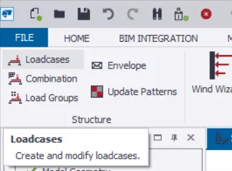
- There will be an option called Loadcases on the left hand side of the screen just click on that option just as shown in the below given image:
- After that there will be another dialouge box named as the load cases, in that dialouge box add more load cases according to our need just as shown in the below given image:
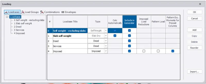
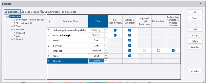
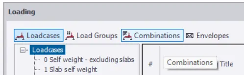
- After that create load combinations and to create load combination there will be another option named as the Load Combinations in that dialouge box just click on that option just as shown in the below given image:
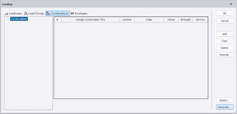
- After that at the end of the dialouge box there will be an option called Generate... click on that option just as shown in the below given image:
- After that just follow the instructions just as shown in the below given imge:
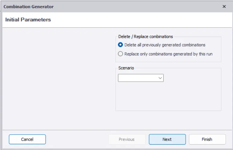
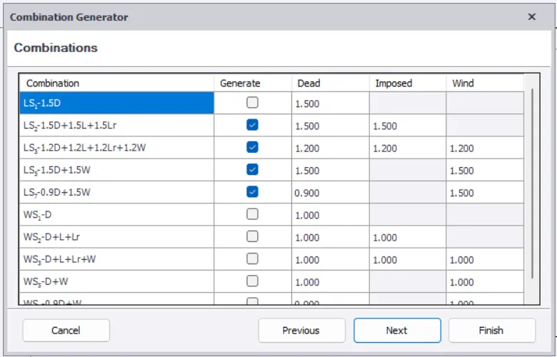
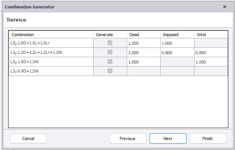
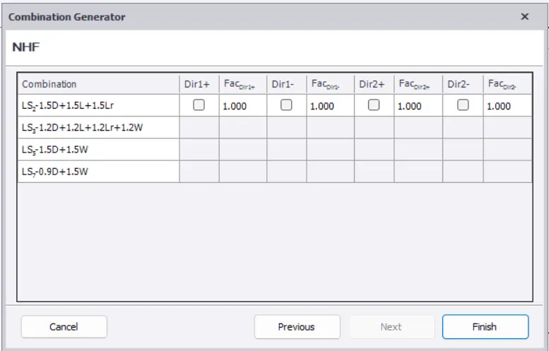
- Now there will be another window opens and in that window create the load combinations according to the need of the model just as shown in the below given image:
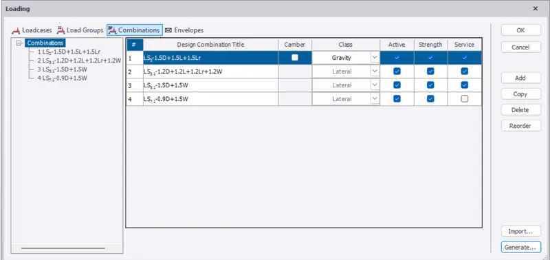
- Now select the levels where we want to add the loads and the load combinations just as shown in the below given image:
Ground Floor:
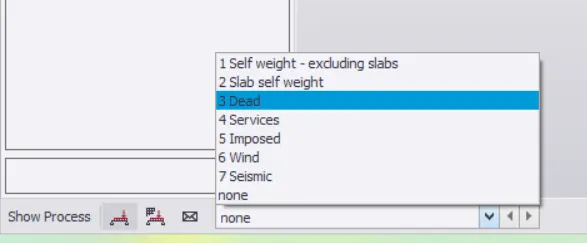
- Now go to the bottom left corner of screen where we will be selecting the loads. Just click on the option and select the Dead load option just as shown in the below given image:
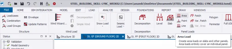
- And now go to the Load tab then there will be an option at the Panel loads tab Area just click on that option just as shown in the below given image:
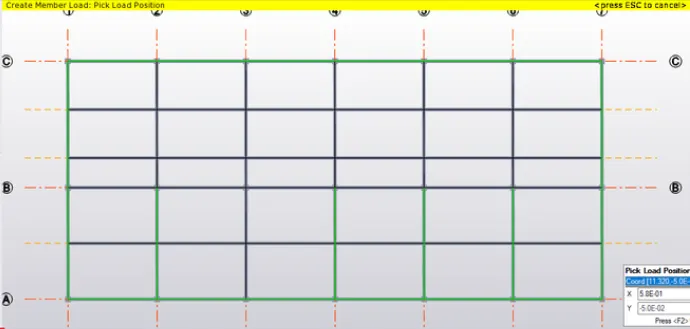
- Now change the load as the finish load and then apply the loadings just as shown in the below given image:
Second floor:
- Do the same procedure for the remaining floors. Below is the given image of the applied load on the second floor:
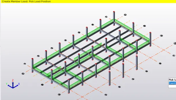
- Finally, dead load (ie, member load) is applied on the ground floor as shown below just as shown in the below given image:
First Floor:
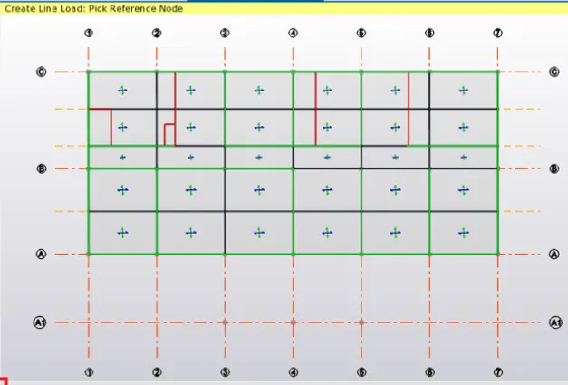
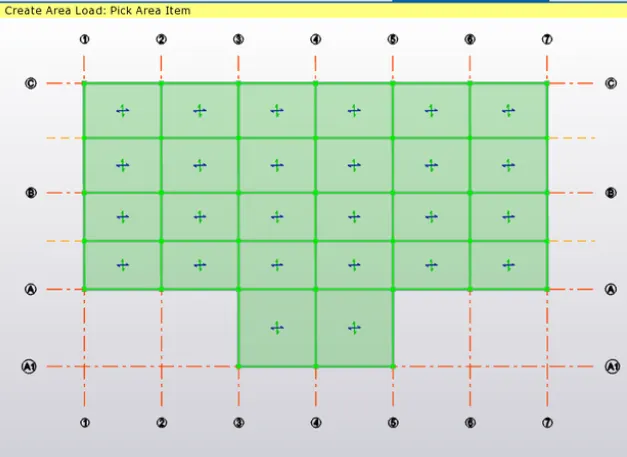
- Select the Dead loadcase from the loading tab.Select area load from ribbon window to provide floor finishes load on the slab.In property window, change load to 1.2 kN/m2 along global Z direction.
- Pick the area to create load area of 1.2 kN/m2 just as shown in the below given image:
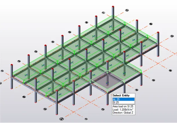
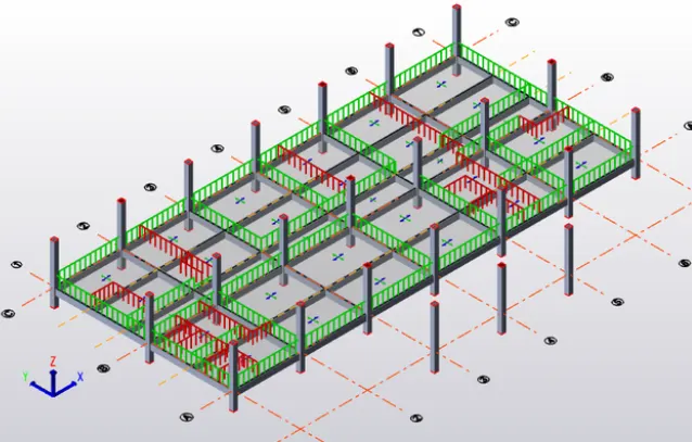
- Next apply brickwall load of 16.8 kN/m by selecting Full UDL and UDL from ribbon tab under member load.Then apply prefabricated load of 1 kN/m by selecting Full UDL just as we can see in the below given image:
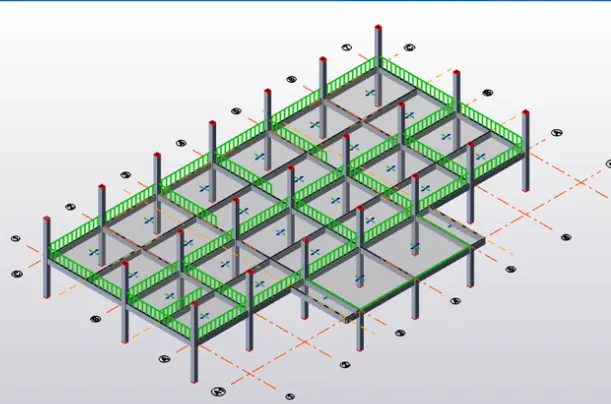
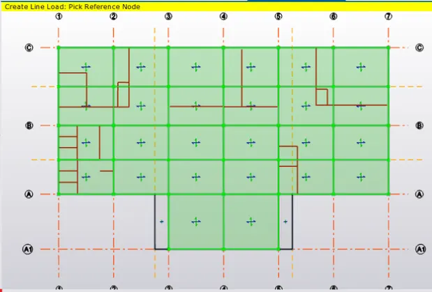
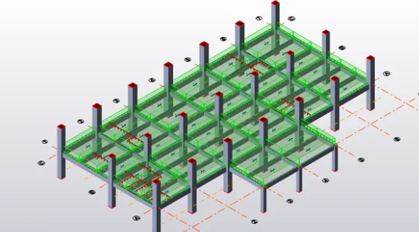
- Therefore, dead loads are applied on the first floor just as shown in the below given image:
Roof floor:
- Select the Dead loadcase from the loading tab.Select area load from ribbon window to provide floor finishes load on the slab.In property window, change load to 1.2 kN/sq.m along global Z direction.
- Pick the area to create load area of 1.2 kN/sq.m just as we can see in the below given image:
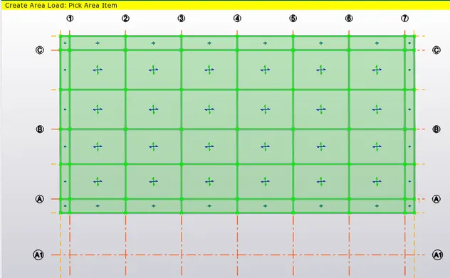
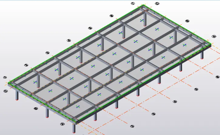
- Next, apply parapet load on the roof floor.Assume height of parapet as 1.1m, density of brick is 20kN/cub.m, thickness of the parapet wall is 150mm.Therefore, parapet wall load is 3.3kN/m.
- Parapet load is applied on the edges just as shown in the below given image:
2- Service Load:
Given Data:
- Service load on the slab for each floor = 0.3 kN/sq.m.
- Volume of the tank = 3m x 3m x 2m.
- Height of the tank = 2m.
- Take density of water = 10kN/cub.m.
- Weight of the water tank = 2m x 10kN/cub.m = 20 kN/sq.m.
PROCEDURE:
Apply service loads that we just calculated on the model:
Ground Floor:
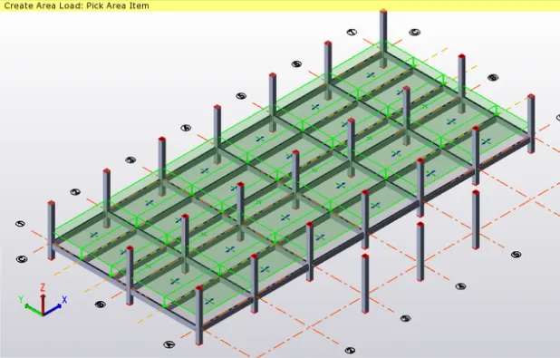
- Select the service loadcase from the loading tab.Select area load from ribbon window to provide floor finishes load on the slab.In property window, change load to 0.3 kN/sq.m. along global Z direction.
- Pick the area to create load area of 0.3 kN/sq.m just as we can see in the below given image:
First Floor:
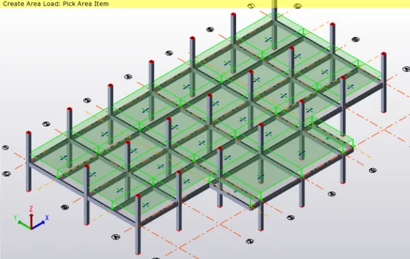
- Select the service loadcase from the loading tab.Select area load from ribbon window to provide floor finishes load on the slab.In property window, change load to 0.3 kN/sq.m along global Z direction.
- Pick the area to create load area of 0.3 kN/sq.m just as we can see in the below given image:
Roof Floor:
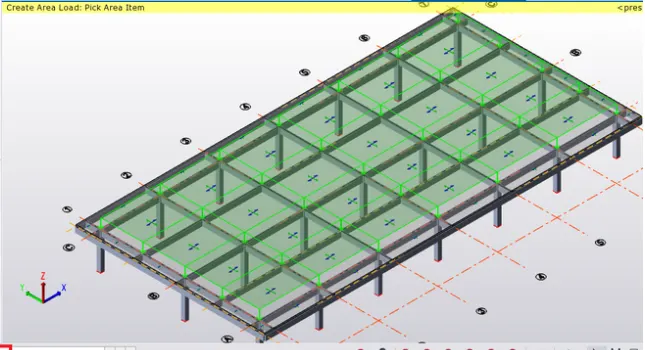
- Select the service loadcase from the loading tab.Select area load from ribbon window to provide floor finishes load on the slab.In property window, change load to 20 kN/sq.m. along global Z direction for the water tank load.
- Pick the area to create load area of 20 kN/sq.m just as we can see in the below given image:
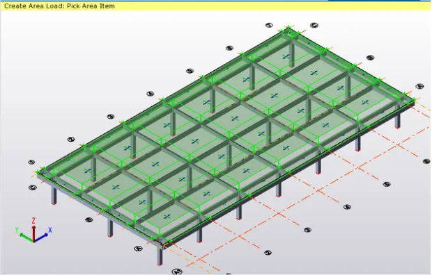
- Similarly, apply 0.3kN/sq.m service load for the cantilever portion just as we can see in the below given image:
3- Live Load:
Manual Calculations:
From IS 875 Part:2 ; Table 1 we take the live loads as:
- Workshop- 5 kN/sq.m.
- Staircase- 5 kN/sq.m.
- Administration room- 5 kN/sq.m.
- Store room- 5 kN/sq.m.
- Meeting room- 5 kN/sq.m.
- Conference room- 5 kN/sq.m.
- Corridor- 5 kN/sq.m.
- Toilet- 2 kN/sq.m.
- Rest Room - 2 kN/sq.m.
- Canteen- 3 kN/sq.m.
- Office room = 3 kN/sq.m.
- Equipment room = 10 kN/sq.m.
PROCEDURE:
Ground Floor:
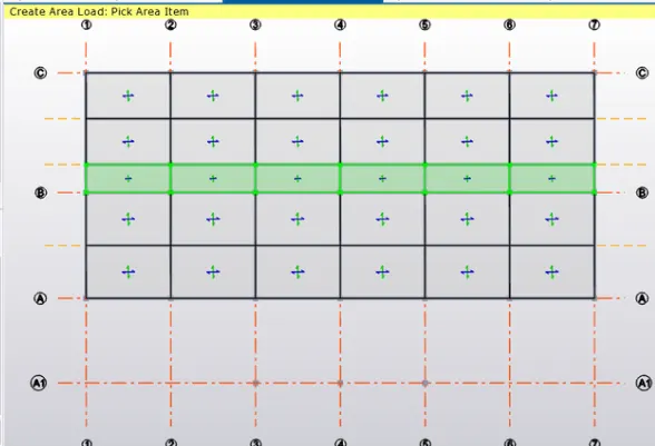
- Select the Imposed loadcase from the loading tab.Select area load from ribbon window to provide live load on the slab.In property window, change load to 4 kN/sq.m along global Z direction to apply load for corridor.
- Pick the area to create load area of 4 kN/sq.m just as we can see in the below given image:
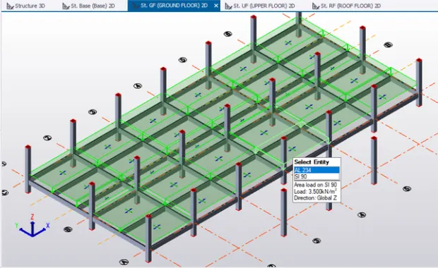
- Similarly, apply load to rest of the slab area based on the requiremements just as shown in the below given image:
First Floor:
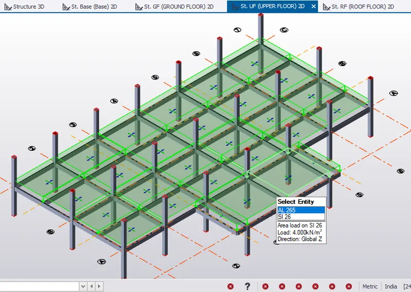
- Select the Imposed loadcase from the loading tab.Select area load from ribbon window to provide live load on the slab.In property window, change load to 2 kN/sq.m along global Z direction to apply load for toilet area.Pick the area to create load area of 2 kN/sq.m just as shown in the below given image:
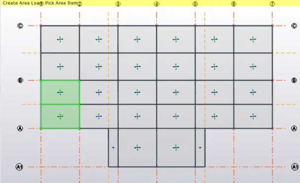
- Similarly, apply load to rest of the slab area based on the requirement as tabulated just as shown in the below given image:
Roof Floor:
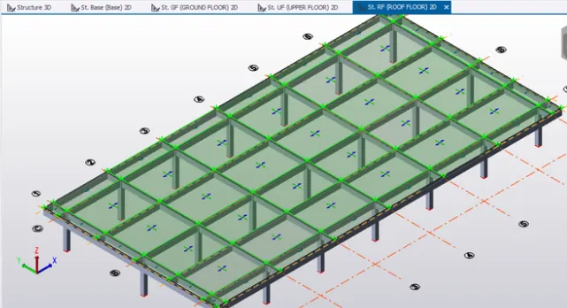
- Select the Imposed loadcase from the loading tab.Select area load from ribbon window to provide live load on the slab.In property window, change load to 2 kN/sq.m along global Z direction to apply load for toilet area.Pick the area to create load area of 2 kN/sq.m just as shown in the below given image:
4- Wind Load:
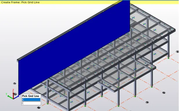
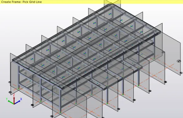
- Firstly, go to the Model tab then there will be an option named as the Frame just click on that option.Pick the grid line to create frames to create wind panels. Therefore, frames are created as shown in the below given image:
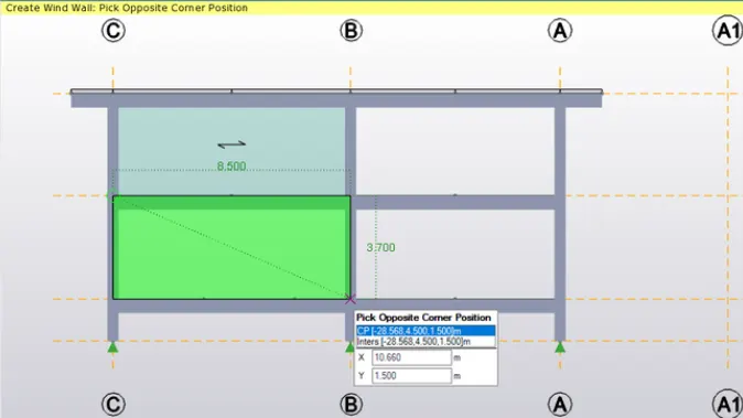
- Select frame 1 from project window to create wall panel for the structure.Select wall panel from ribbon tab.Pick the corners positions of the frames to create wind wall as shown below.
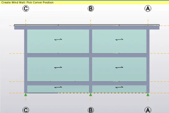
- Similarly, create wall panels for other frames also.After, create roof panel for structure.
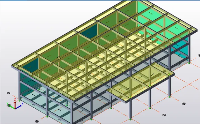
- Check in 3D scene view and the 3D-View is given in the below given image:
Manual Calculation for Wind Load:
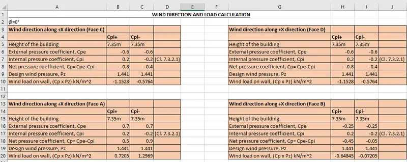
For wind load calculation, consider IS 875-3 (2015) for design report.
Given, basic wind speed as 50m/s and terrain category as 2.
Given Data:
Life of the structure= 50 years (Table 1, Cl. 5.3.1)
Class of structure = B (Cl. 5.3.2.2)
Total length of the building, l= 36 m
Total width of the building, w= 22 m
Total height of the building, h= 7.35 m
Therefore, l/w= 1.64 and h/w= 0.334.
Step 1:
External pressure cofficient, Cpe (As per IS 875-3, Table 5):
- Building height ratio= h/w< 1/2
- Also, Building plan ratio= 3/2< l/w< 4
Step 2:
Find factors (k1, k2, k3, k4)
- From table 1 for wind speed of 50 m/s, k1= 1
- From table 2 with terrain category 2 and class of the building B.
- Building height= 7.35m
- For 10m tall building, k2 value is 0.98.
- Therefore, 8.1 m tall building, k2= 0.98
- From Cl. 6.3.3, Topography Factor, k3= 1
- From Cl 6.3.4, Importance Factor, k4= 1 (for all other building)
Step 3:
To calculate Design Wind Speed (Vz) (from Cl 6.3):
Vz= Vb x k1 x k2 x k3 xk4= 50x 1 x 0.98 x 1 x 1.
Vz= 49 m/s.
Step 4:
Design wind Pressure (Pz) :
Pz = 0.6 x Vz^2 =0.6 x 49^2 = 1440.6 N/m^2
Pz =1.441 kN/m^2
Step 5:
Wind direction (upto roof level):
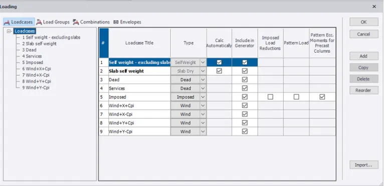
- To create wind load, select loadcase from load tab.
- Add loadcases Wind+Y+Cpi, Wind+Y-Cpi, Wind+X+Cpi and Wind+X-Cpi.
Wind+X+Cpi:
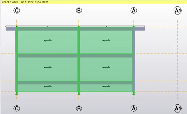
- Select frame 1 from project window.Also, select Wind+X+Cpi from the loading window.Select the area load, change load intensity to 0.73 kN/sq.m and change direction to global X.
- Pick the area to create area load just as shown in the below given image:
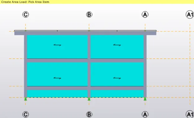
- Similary, select frame 7, select Wind+X+Cpi from the loading window.Select the area load, change load intensity to -0.65 kN/sq.m and change direction to global X just as shown in the below given image:
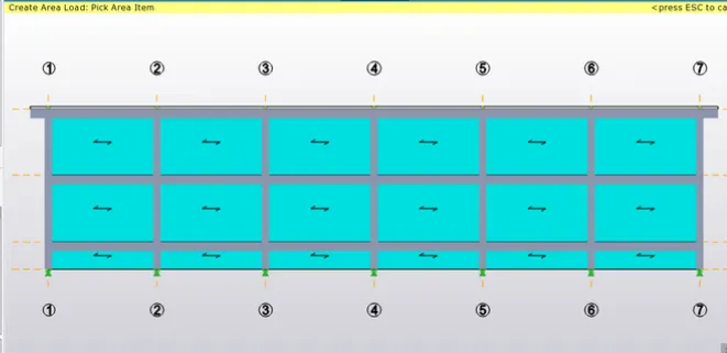
- Next to apply internal pressure, select frame C, select Wind+X+Cpi from the loading window.Next, select the area load, change load intensity to -1.2 kN/sq.m and change direction to global Y just as shown in the below given image:
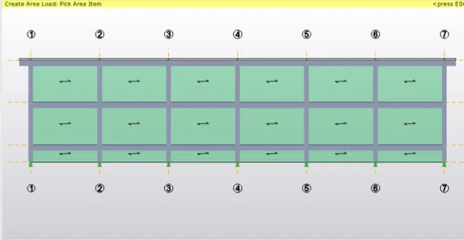
- Similarly, select frame A, select Wind+X+Cpi from the loading window.Select the area load, change load intensity to -1.2 kN/sq.m and change direction to Y just as shown in the below given image:
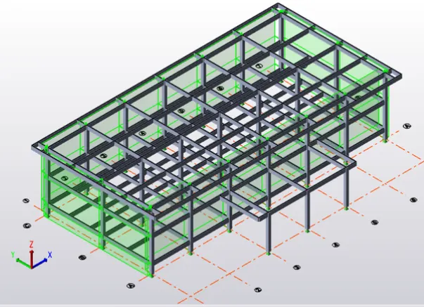
3D-VIEW:
4- Seismic Load:
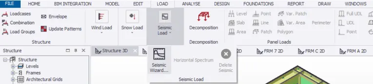
- The very first step in order to apply the seismic loading. First go to the Load Ribbon Tab then there will be an option named as the Seismic Load just click on that option just as shown in the below given image:
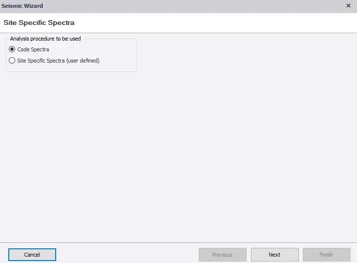
- Then there will be another dialouge box named as the Seismic Wizard and in that dialouge box there will be an option named as the Analysis procedure to be used and in that there will be another option Code Spectra, select Code spectra for analysis procedure and then click Next option just as shown in the below given image:
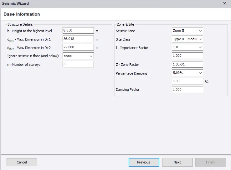
- Structural Details under base information is automatically inputed. Then set the seismic zone to 2 and site class to 2.
- Importance factor and percentage damping is obtained from Table 6 and 3 respectively of IS 1893-1 and zone factor from Table 2 just as shown in the below given image:
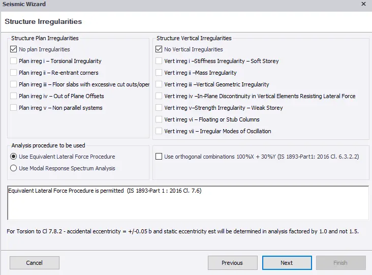
- No structural irregularity in the structure as mentioned in Table 4 and 5 just as shown in the below given image:
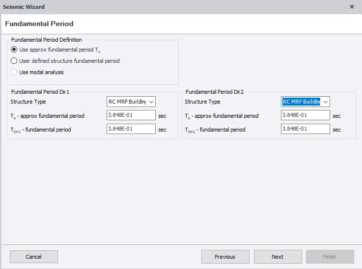
- Next use approxmiate fundamental period. Set RC MRF building without any masonry infill in both direction just as shown in the below given image:
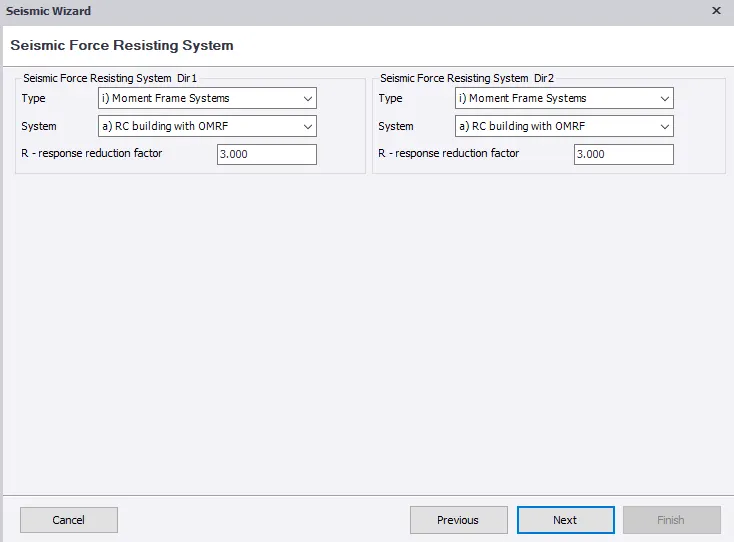
- Next set structure type to seismic force resisting system in both direction just as shown in the below given image:
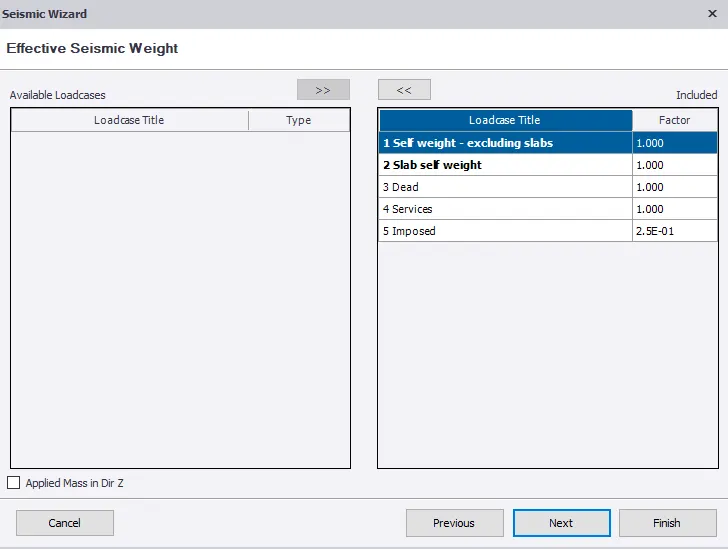
- Now, select all the loadcases and set factor for imposed load to 25% for refered from table 8 just as shown in the below given image:
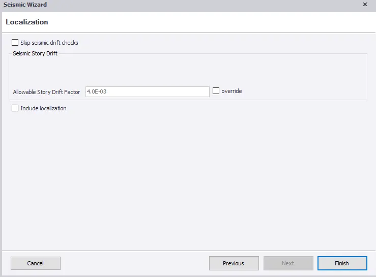
- Then set the allowable storey drift factor as 0.004 and then click finish just as shown in the below given image:
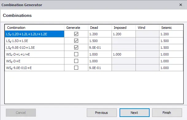
- Delete all previously generated combinations and select the combinations to be generated.Then click on Finish option just as shown in the below given image:
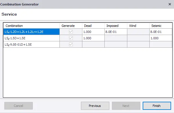
- Select the load combination from load tab to see the combinations generated just as shown in the below given image:

- After that there will be another dialouge box named as the Loading and in that dialouge box all the combinations have been generated just as shown in the below given image:
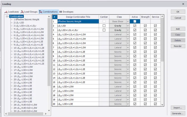
- Now validate the model to check any error.
ANALYSIS:
- Next we will be analysing the structure and to analyse the structure go to Analyse ribbon tab, and in that tab there will be an option named as the 1st order linear analyse just as shown in the below given image:

- Then there will be another dialouge box named as the Select Loading and in that dialouge box select all the load combinations to run analysis just as shown in the below given image:
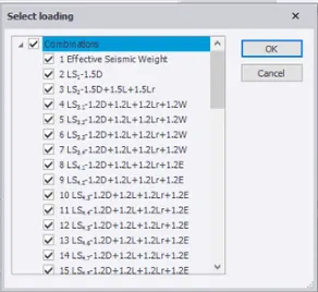
- Next, in project window, highlight the node with maximum positive displacement.Therefore, a node is picked in solver view just as shown in the below given image:
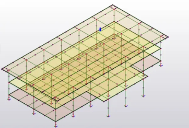
Deflection Diagram:
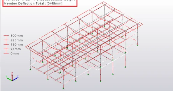
- In results view, under results tab select total deflections for different load combinations.Total deflection for effective seismic weight is 49mm just as shown in the below given image:
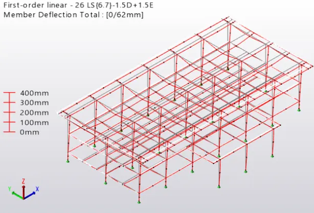
- Therefore, maximum deflection is shown in load combination 26 which is due to seismic load just as shown in the below given image:
- Select frame B from project window.Check deflection along Z direction in result view just as shown in the below given image:
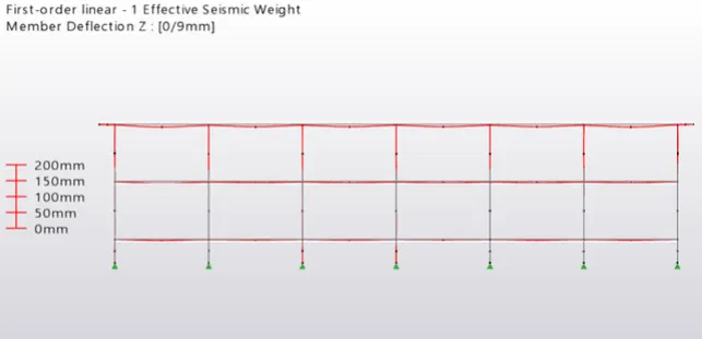
Deflection due to gravity in frame B:
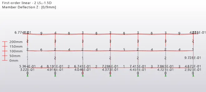
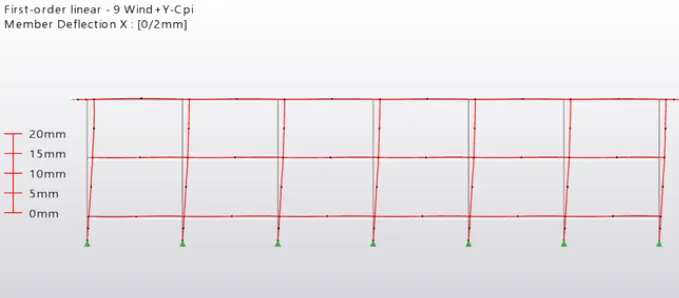
Deflection due to wind along X direction:
Axial Force Diagram:
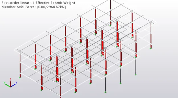
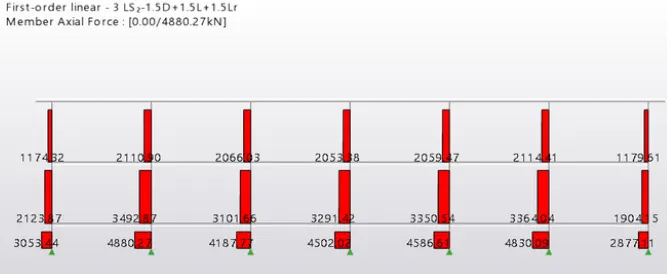
- Similarly, select frame B to check axial force diagram.Maximum axial force value is shown in load combination 3 as shown below. Also check for different load combinations as shown in the image below:
Shear Force Diagram:
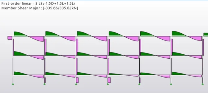
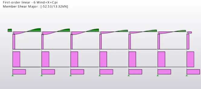
Shear major for wind load condition:
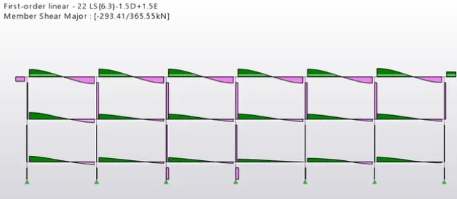
Shear major for load combination with seismic load:
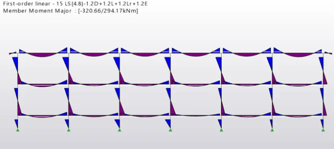
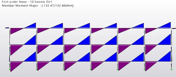
Bending Moment Diagram:
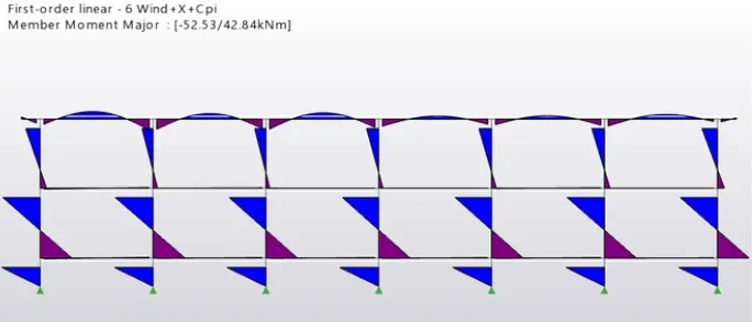
Bending major for wind load condition:
Bending major for seismic load condition:
Member Design:
1- Slab design:
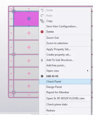
- In order to design the slab member, go to the roof floor in scene view and then select a panel to check the panel just as shown in the below given image:
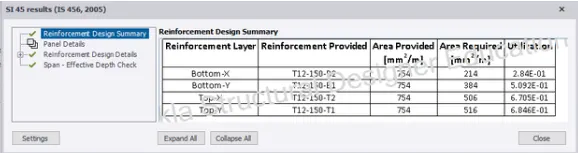
- Then there will be another dialouge box named as the SI 45 results (IS 456,2005) and in that dialouge box provide T12 bars at 150 mm centre to centre spacing as shown in the below given image:
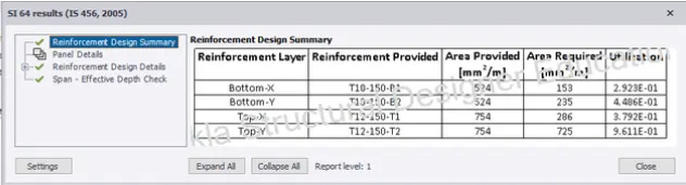
- Similarly, check all slab panels in roof floor. Check panel for SI64. Provide T10 at 150mm spacing as bottom reinforcement and T12 as top reinforcement just as shown in the below given image:
- Check in review view, the status of the roof slab just as shown in the below given image:
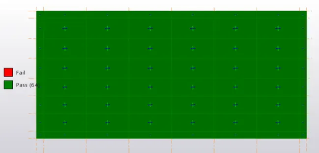
- Similarly, check slab panels for ground and first floor as shown in the below given image:
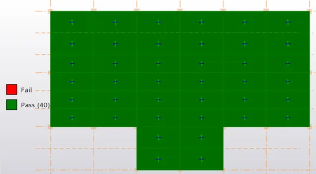
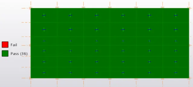 2- Beam design:
- For frame B, Check the maximum bending moment acting in the beam where maximum BM is acting in roof floor just as shown in the below given image:
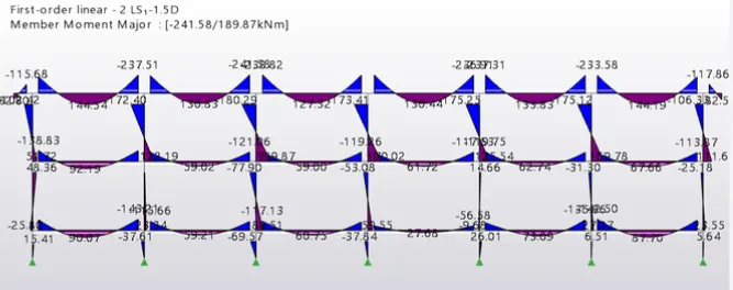
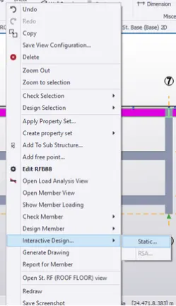
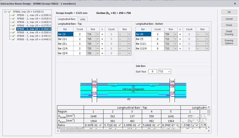
- Next select the beam RF-B88 for interactive design just as shown in the below given image:
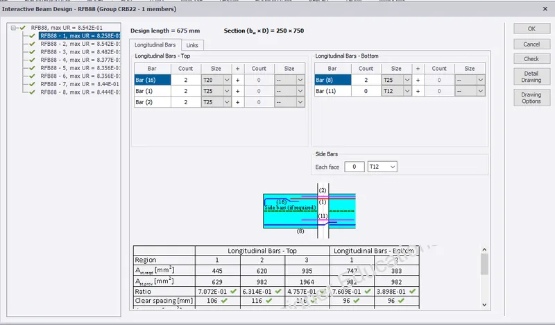
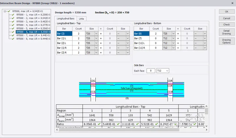
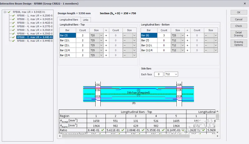
- The beam with section size 230mm x 500mm doesnot satisfy the design.Therefore, change the section to 250mm x750mm. Again, interactive design is done.Select the first span. Provide T20 and T25 bars.
- Therefore,UR=0.825Similarly, check for each span.
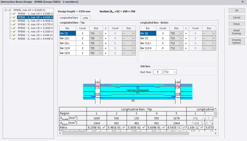
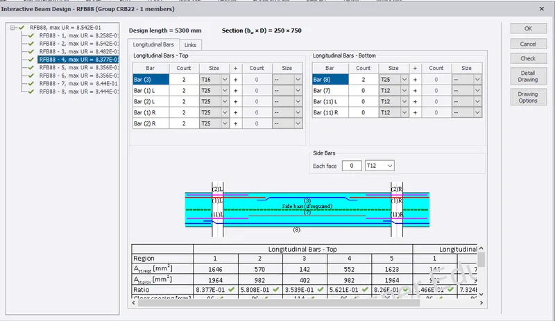
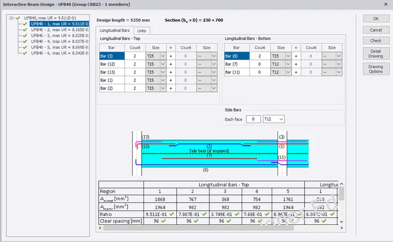
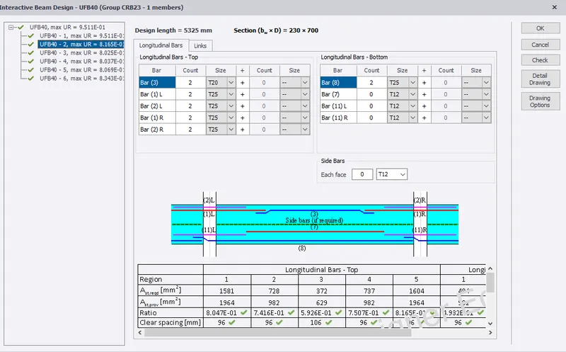
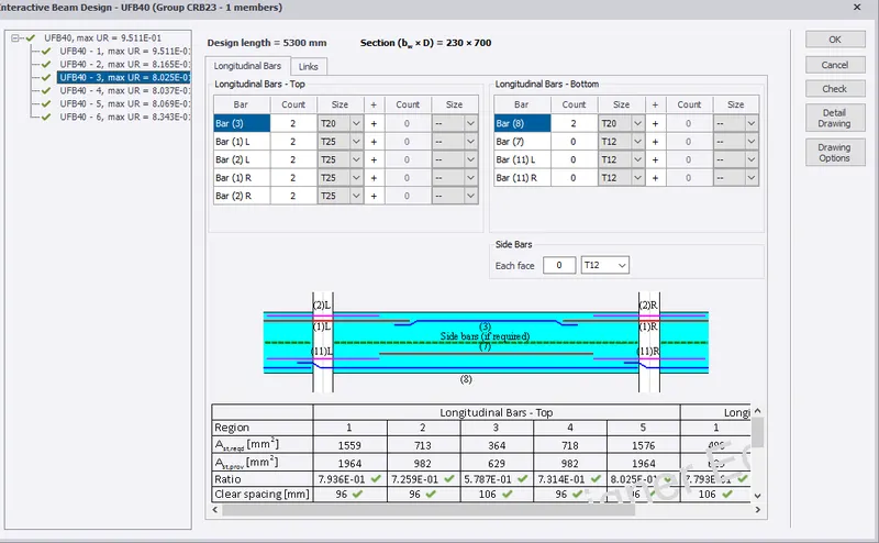
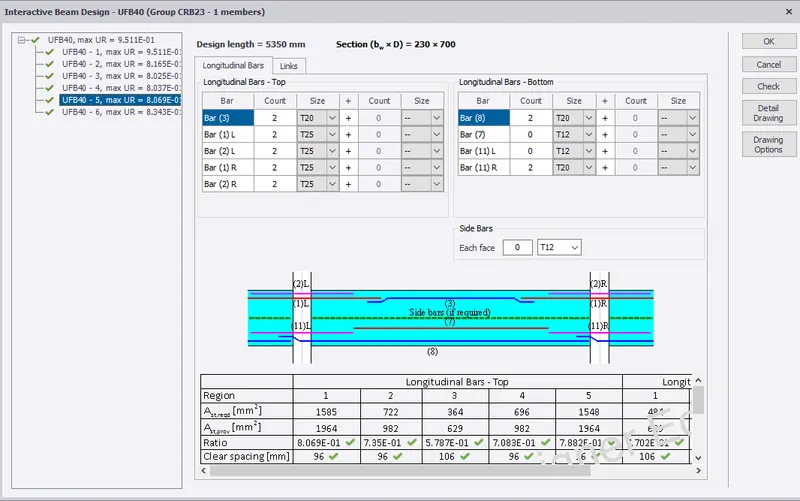
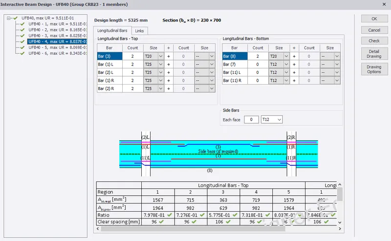
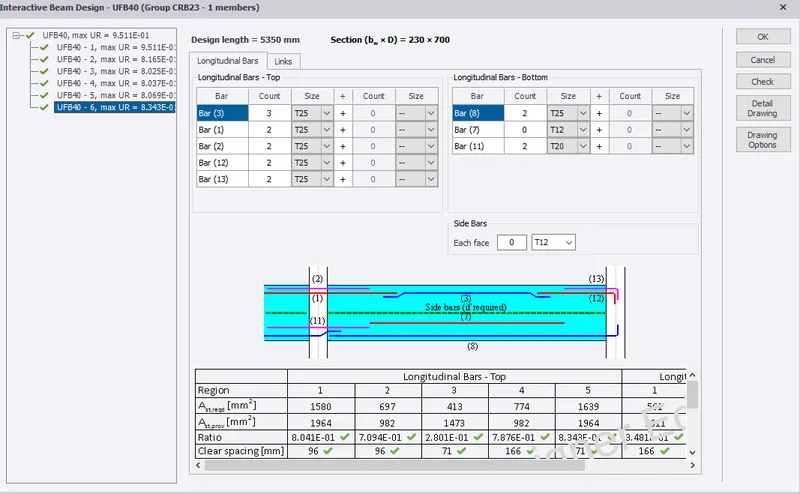
- Select first floor beam UFB40 for interactive design.Provide section size 230mm x 700mm just as shown in the below given image:
3- Column design:
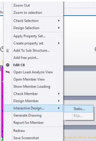
- Select frame B from project window.Select the column to be designed. Right click the member to select Interactive Design just as shown in the below given image:
- Then there will be another dialouge box named as the Interactive column design so in that dialouge box as we can see in the below dialouge box there are few errors as seen below:
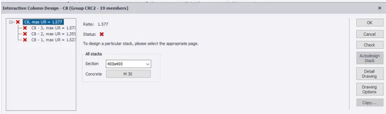
- Change the member section to 650mm x650mm.Select Stack 1 of C8 column as shown utility ratio is 0.917.Provide Torsional bars of 32mm diameter for both principle and intermediate bar and also T10 bars as link bars which pass the design criteria just as shown in the below given image:

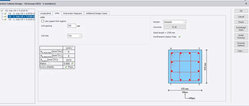
- Similarly for stack 2 and 3 provide both principle and intermediate bar as provided for Stack 1.
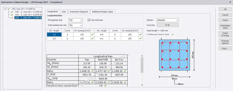
- Hence safe.Select column C39 for interactive design.Change the column section size to 650mm x650mm.Select stack 1, provide the bar size to T32 for both principle and intermediate bars and T10 for link bars.Similarly, for stack 2 and 3 provide T32 barsTherefore, UR change to 0.733, 0.64 and 0.91 for stack 1,2 and 3 respectively as we can see in the below given image:
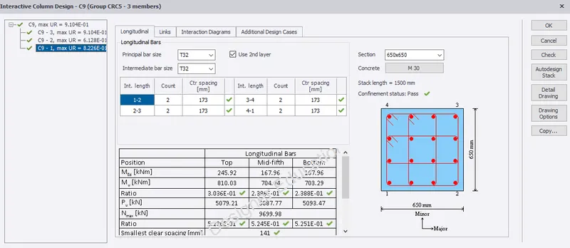
- Select column 9 for interactive design.Change the column section size to 650mm x650mm.Select stack 1, provide the bar size to T32 for both principle and intermediate bars and T10 for link bars.Therefore, UR for stack 1,2 and 3 are 0.83, 0.612 and 0.91 as shown in the below given image:
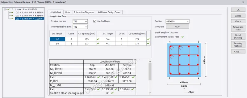
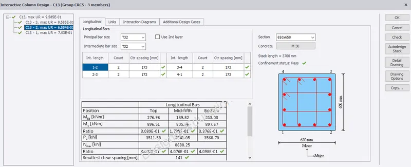
- Select column C13 for interactive design.Change the column section size to 650mm x650mm.Select stack 1, provide the bar size to T32 for both principle and intermediate bars and T10 for link bars.Therefore, UR for stack 1,2 and 3 are 0.73, 0.66 and 0.98 as shown in the below given image:
- Similarly, check interactive design for rest of the columns in the structure.
4- Foundation Design:
- Next we will be designing the foundation and in order to design the foundation just go to the Foundation ribbon tab and in that ribbon tab there will be an option named as the Catalouge just click on that option just as shown in the below given image:

- Then there will be another dialouge box named as the Pile Catalouge and in that dialouge box edit the base floor, set pile type in catalogue and Edit data, materials and pile capacity for piles just as shown in the below given image:
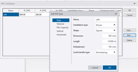
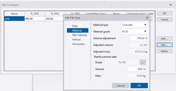
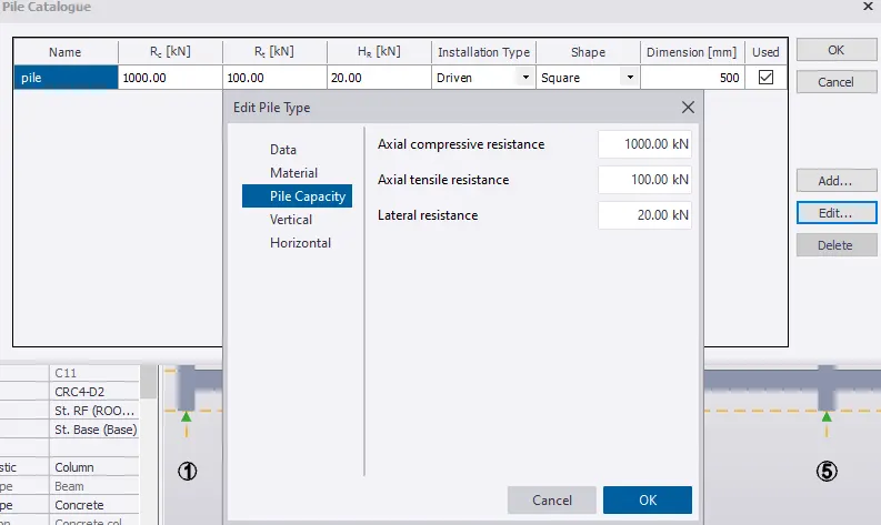
- Next go to the Foundation tab then there will be an option named as the Pile Cap Column just click on that option just as shown in the below given image:

- Pick the location to create column isolated pile cap position just as shown in the below given image:
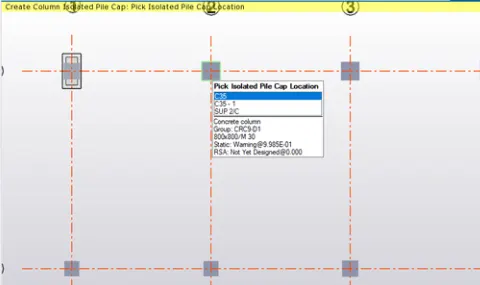
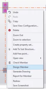
- Select to design the member just as shown in the below given image:
- Then there will be another dialouge box named as the PC1 results (IS 456,2005) and check the errors, so as we can see in the below given image that there are no errors it means it is good to go then just as shown in the below given image:
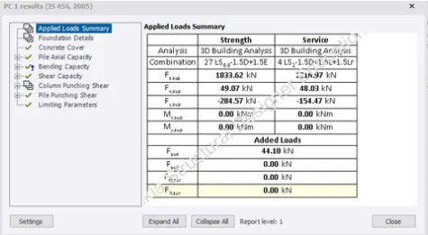
- Similarly, check design for all pile cap.
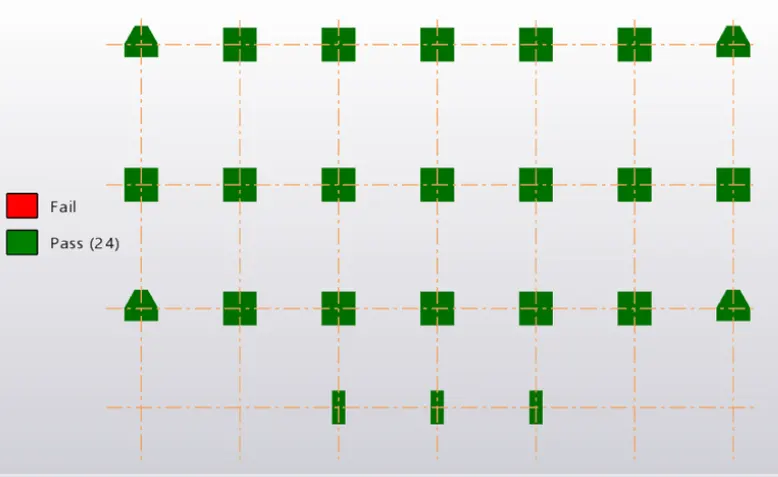
- In review view, check the status of the pile cap just as shown in the below given image:
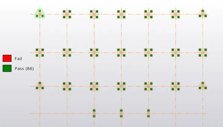
- Also, check status of pile in review view. Hence safe as shown below:
Report Generation:
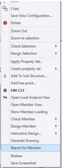
- Select a column to generate report for the member just as shown in the below given image:
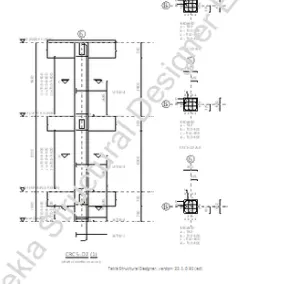
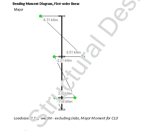
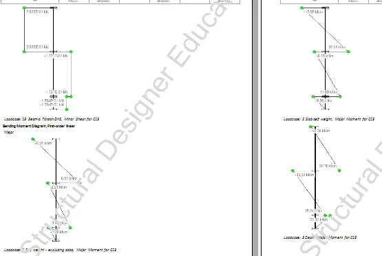
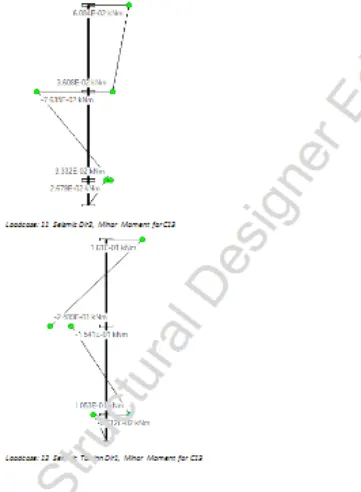
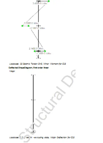
- Report for the particular column is generated with cross section.Select Member report to include loading, shear force, bending moment, deflection and axial force diagram along with design calculation and summary just as shown in the below given image:
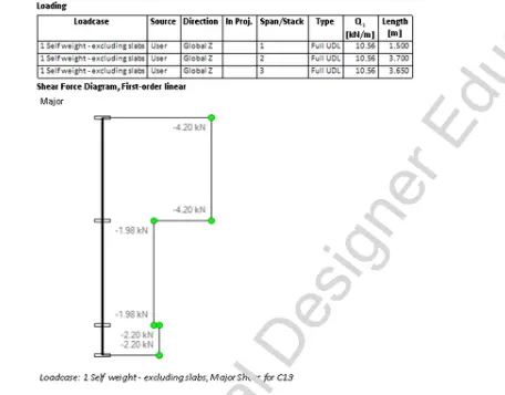
Report for loading and shear force diagram:
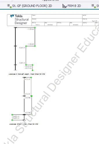
Bending moment diagram for both major and minor at different loadcases:
Deflection diagram for both major and minor at different loadcases:
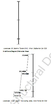
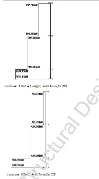
Axial force diagram for different loadcases:
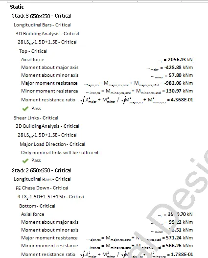
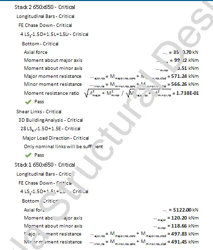
- Design Calculation and summary are shown below:
Concrete Beam Report:
- To generate report for RC beam, select Report for Member just as shown in the below given image:
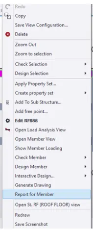
- Therefore, report for the beam is generated.
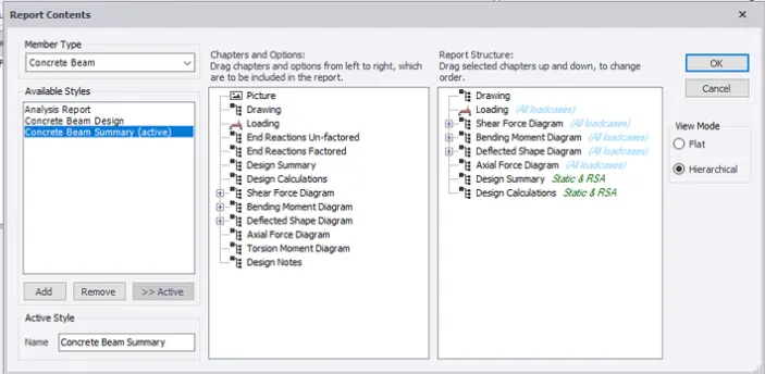
- Next, select Member report to edit the contents of the beam report.
- To create report, drag selected chapters under structures which includes drawings, loadings, shear force, bending moment, deflection and axial force diagram along with design calculation and summary. Click OK just as shown in the below given image:
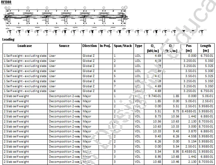
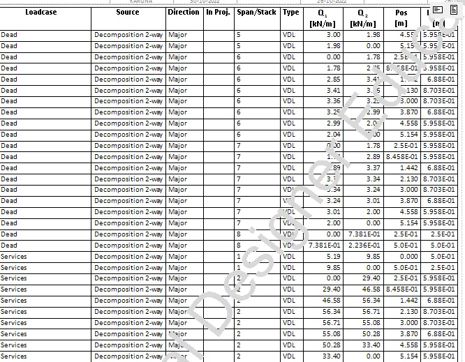
Roof beam (RFB88) drawing and loading for different loadcase:
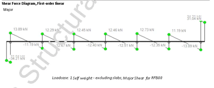
Shear force diagram:
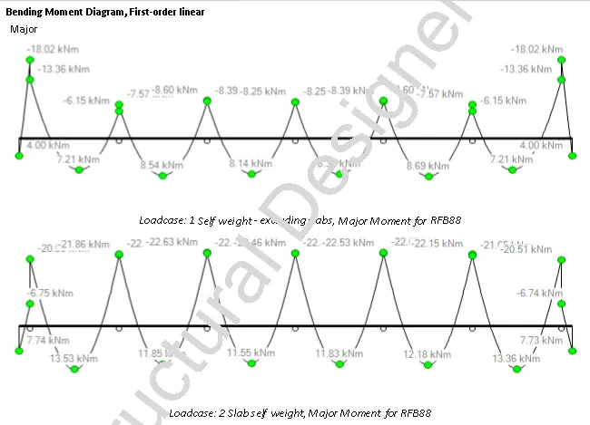
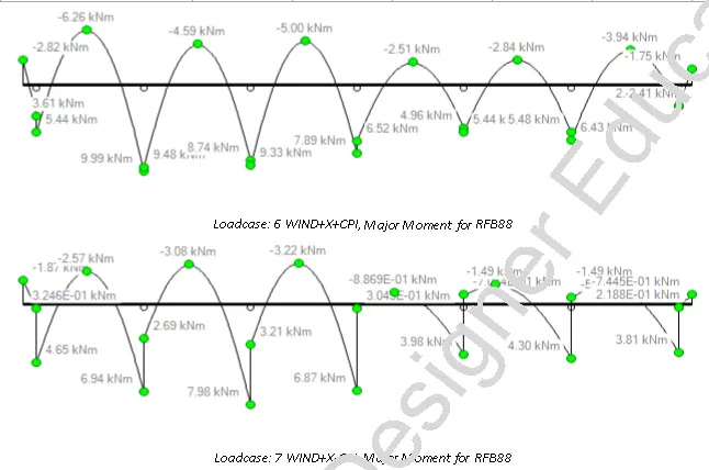
Bending moment diagram:
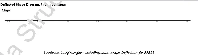
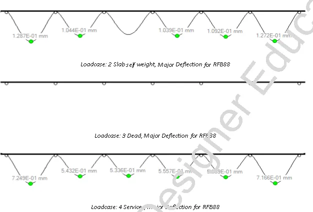
Deflection diagram:
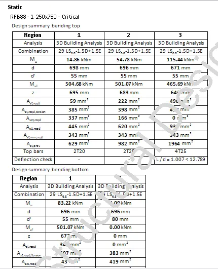
- Design summary for roof beam (RFB88-1, 2) is generated as shown in the below given image:
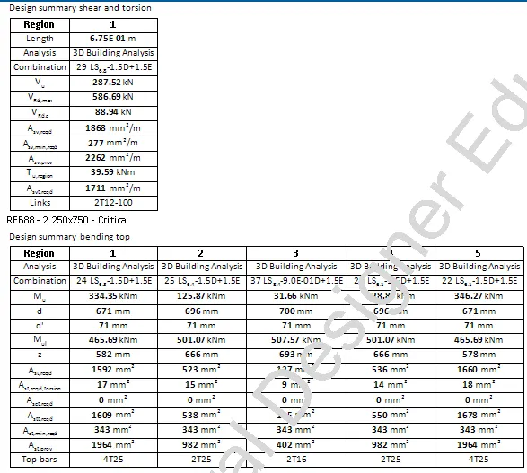
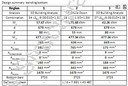
- Similarly, Design summary for roof beam (RFB88-3 till 8) is generated.
- Design calculation for roof beam (RFB88-1,2) is generated as shown below:
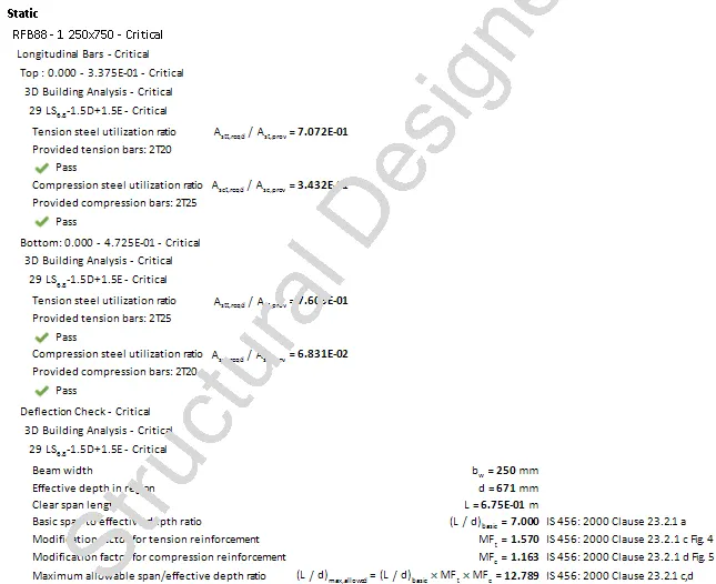
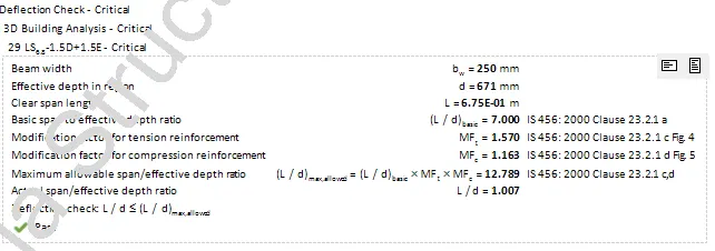
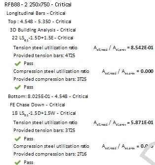
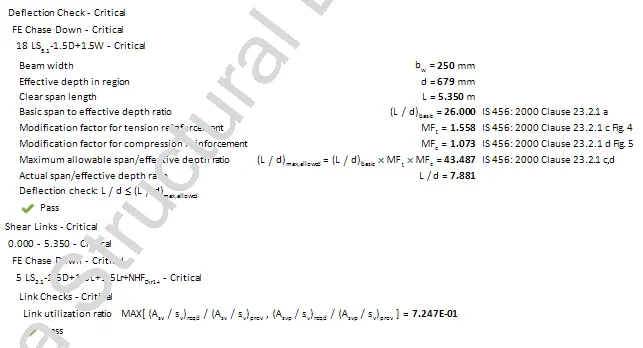
- Similarly, Design calculation for roof beam (RFB88-3 till 8) is generated.
Concrete Slab Report:
- Go to roof floor, To generate report for RC slab, select Report for Member as shown in the below given image:
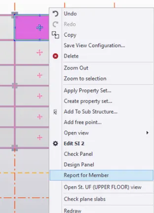
- Therefore, report for the slab is generated.
- Select Member report to edit the contents of the slab report.To create report, drag selected chapters under structures which includes design calculation and summary. Click OK just as shown in the below given image:
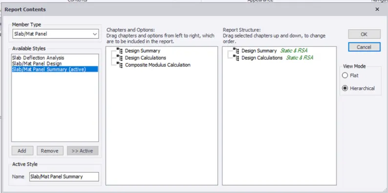
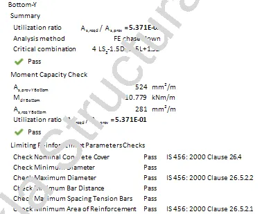
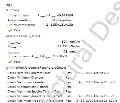
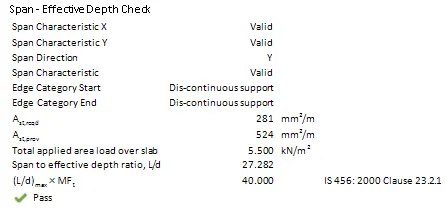
- Design summary and calculation for slab S1, Panel SL2 is generated just as shown in the below given image:
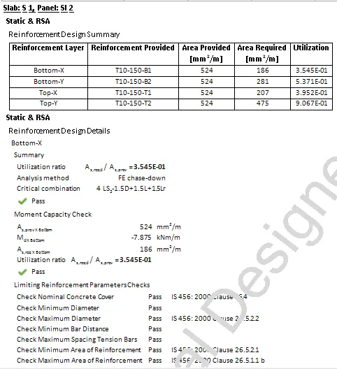
Foundation Report:
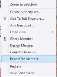
- Go to base floor, To generate report for RC pile cap, select Report for Member just as shown in the below given image:
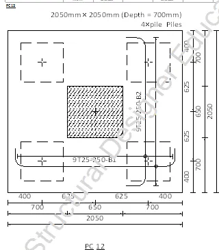
- Drawing of pile cap PC 8 is generated as shown in the below given image:
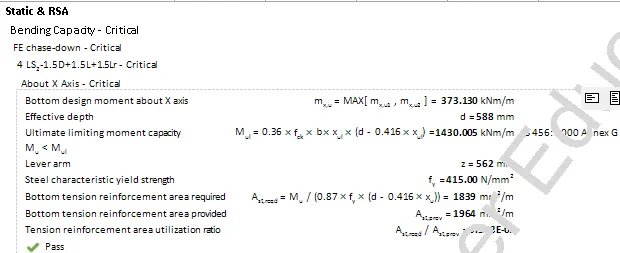
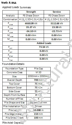
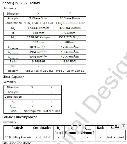
- Design calculation and summary for pile cap are generated as shown in the below given image:
Layers settings and generate drawings:
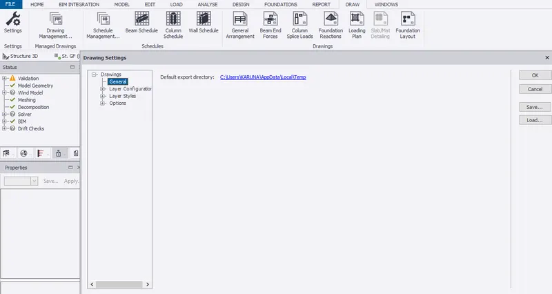
- Go to draw in tab window.
- Select drawing settings to set layers for the model so as to generate plan drawing just as shown in the below given image:
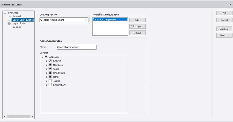
- Select layer configuration to modify the drawing category.
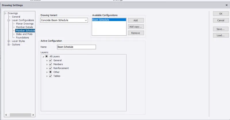
- Select member schedule to set layer configuration for beams and columns just as shown in the below given image:
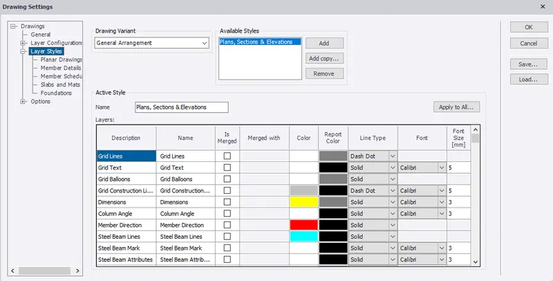
- Layer styles can be modified in drawing variant.
- Select Planar drawing from layar styles to change colour. Click ok just as shown in the below given image:
- Go to Frames in scene view.
- Select general arrangement from ribbon tab to create and save drawings in 2D view just as shown in the below given image: