Project 2 Adaptive Cruise Control
Aim of the project-
To design a system to reduce the stress on driver by automatically controlling the vehicle speed and by maintaining a predefined minimum distance from preceding vehicle using radar and camera input of both lead vehicle and driver vehicle.
Description-
Adaptive Cruise Control Feature adjust the speed of the car according to the lead vehicle which is rolling in same way to provide more comfort and safety to the passenger. As well as it helps to driver in traffic condition by keeping safer distance from other vehicles and move accordingly.
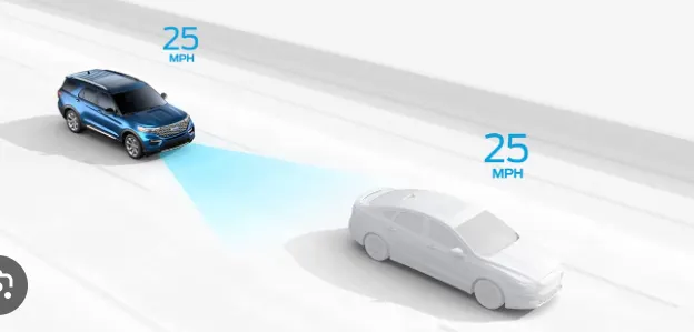
In this project we are going to design a system who can perform all these task
Model - Adaptive Cruise Control
Requirement No 1
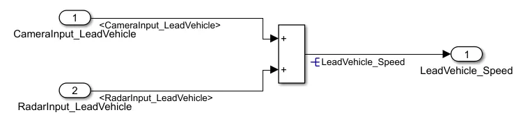
A separate subsystem is designed to fullfill this requirement. Input to this subsystem are taken from the Camera and Radar which sense the Lead vehicle data i.e. its position , its distsnce from drive vehicle. In general a algorithem is used to calcute the Radar and Camera input and give respective output to the control unit of Drive car but to reduce the complexity we are going to simply add this signals and give output to the next subsystem.
Blocks used in this subsystem_1-
1- Inports
2- Add block
3- Outport
Model-
Requirement No 2
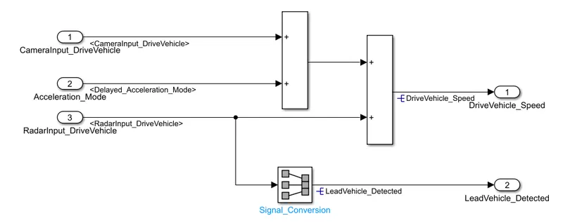
This subsystem is similar to the previous subsystem. According to the requirements providede Inputs to this block are Camera and Radar input of drive vehicle in addition to that a output of subsystem_3 is also provided to this system as an input. that means this block contain theree inputs.
After adding these signals one output is created and another output is created by performing signal conversion operation on Radar input then these two outputs are provided to next subsystem.
Blocks used in this subsystem_2-
1- Inports
2- Add block
3- Outports
4- Signal Conversion
Model-
Requirement No 3
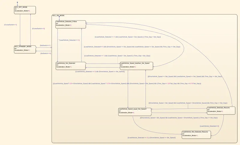
This requirement is done by using State Flow chart, state flow chart contain three other substates in it which decide the operation of ACC , that means in what state the ACC have to be operate for a perticular condition. Input to this subsystem are output of both previous subsystem 1 and 2 and other external inputs Time_Gap, Set_Speed, Set_Gap, CruiseSwitch, SeetSwitch.
Blocks used in this subsystem_2-
1- Inports
2- StateFlow
Model-
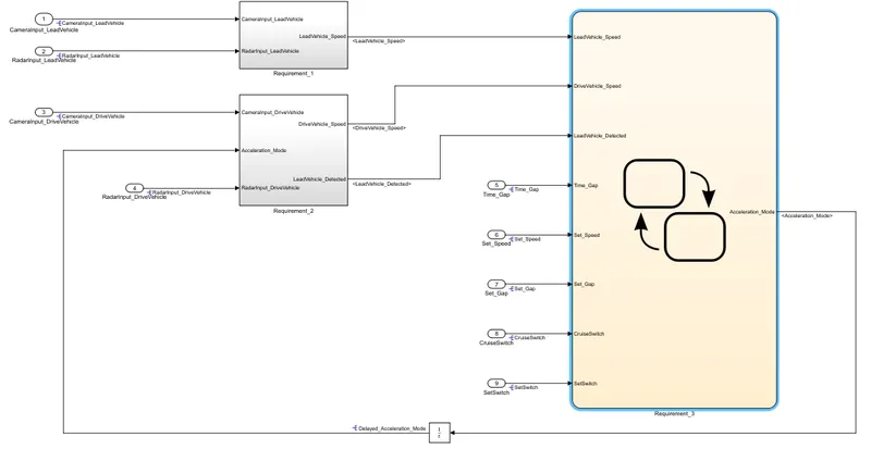
then according to the subrequirements of requirement_3 we have to design the internal structure by enclosing given mentioned signal conditions in requirements,
Requirement Tagging & Traceability
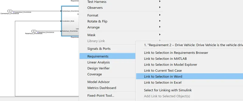
To tag the requirements to the respective subsystem firstly we have to Copy paste and save those requirements in a world format. then just select the single requirement> Go to the model> Right click on that respective block having the same copied requirement> Go to Requirements> link to selection in world. perform these steps to tag all the requirements.
SLDD creation
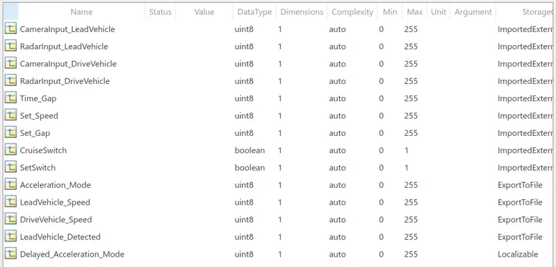
Storage class for Input signals: ImportedExtern; Storage class for Output signal: Export to File; Storage class for local signals: localizable; Storage class for calibration signals: Const.
Configuration Parameter changes
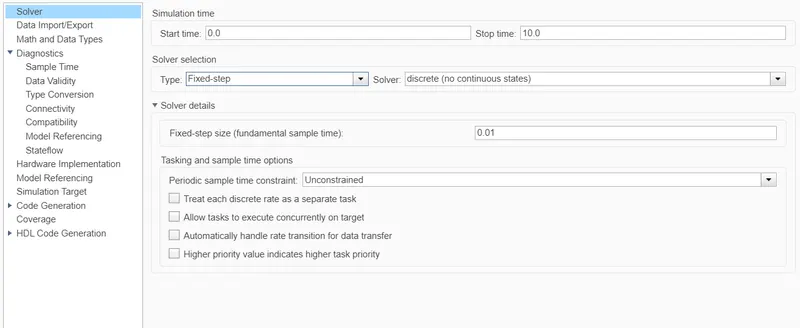
According to the requirement we have to keep step time as 0.01,
And in solver selection 'Type' we have to be select as 'Fixed time' and we have to select solver as to 'Discrete' then in code generstion setting we ahe to enable “Support Floating Numbers”
Code generation settings-
select system tsrget file as ert.tls
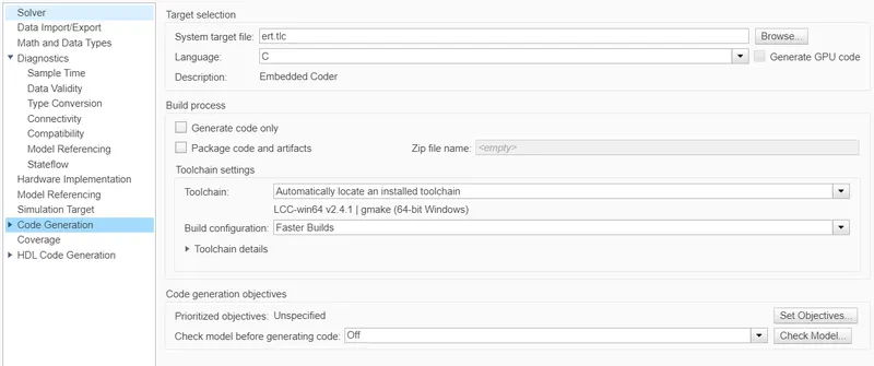
then make moel advisor report - modelling> Model advisor (upper left corner)
then as per reuirement by using Embeded coder do perform code generation task.
Result
This system gives output as Acceleration_Mode as per the input signals from camera and Radar of both vehicles i.e. Lead vehicle and Drive vehicle.