Project 2 Adaptive Cruise Control
Main Project – Adaptive Cruise Control (ACC)
Aim: To devlop adaptive cruise control feature as per the requirement document.
Objective :
- Developing Adaptive Cruise Control feature as per the Requirement Document using MATLAB Simulink.
- Follow all the MBD related processes: Requirement Tagging & Traceability, SLDD creation, Configuration Parameter changes, Model Advisor check & Code Generation.
- In Configuration Parameters: enable “Support Floating Numbers” under Code Generation settings.
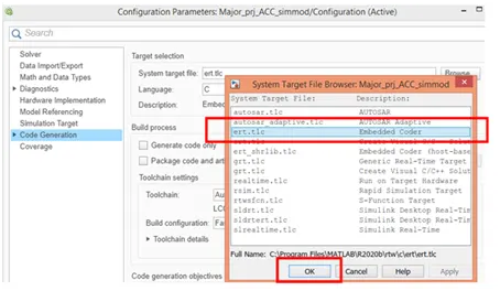
- Use Embedded Coder to generate the code.
Description:
Step 1. Devloping simulink data dictionary as per given requirement.
1.a. Creating .sldd
Go to Modeling → click on Link to Data Dictionary → type appropiate name for sldd → uncheck'Enable model access to base workspace' → click on 'Apply' , 'Ok' → save it in working folder
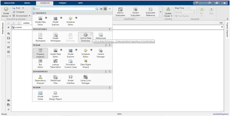
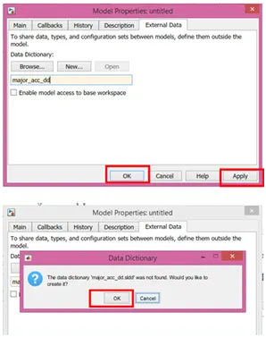
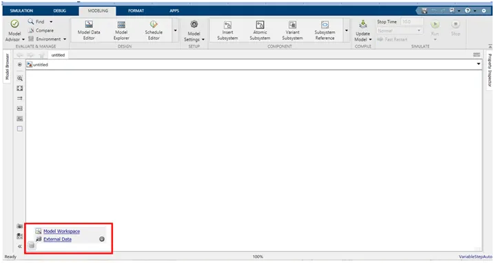
1.b Linked .sldd can be accessed as follows,
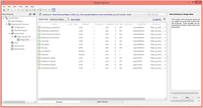
click on Model Data → External Data → Expand External Data → add signals and calibration data to create sldd
.SLDD for as per given requirement
Step2: Developing Adaptive Cruise Control feature as per the Requirement Document using MATLAB Simulink.
2.1 Devloping logic for Requirement 1 and creating its subsystem.
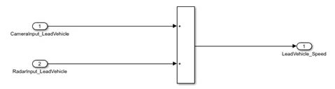
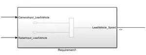
2.2 Devloping logic for Requirement 2 and creating its subsystem.
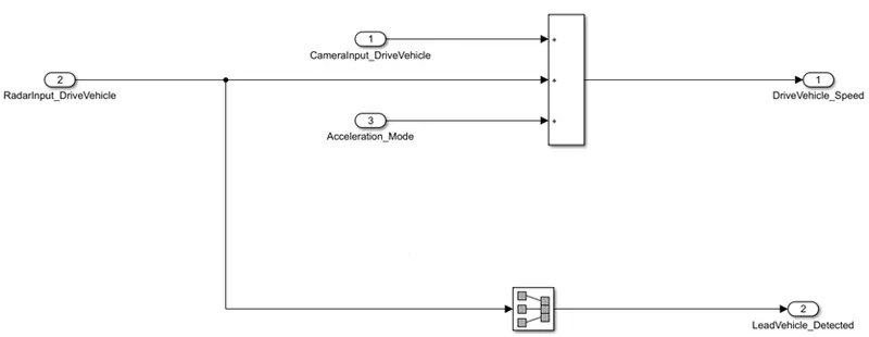
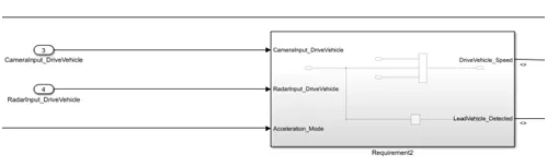
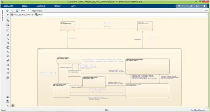
2.3 Devloping logic in state machine for Requirement 3.
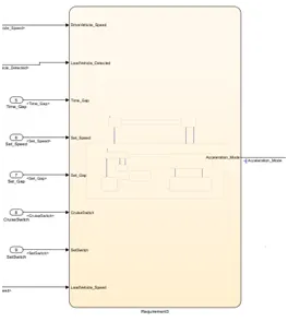
2.4 As Variable Accelration Mode is not intialize in model and it is to be feedback to subsystem(Requirement 2) unit delay block is introduced in feedback path to avoid modelling error.
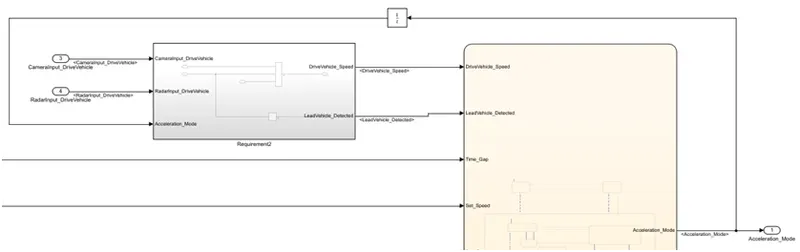
2.5 Creating main subsystem for all requirements.
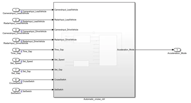
Step 3: Requirement document tagging;
3.1. The word document is created in which details of requirements are given. Perticular text containing requirement details is selected.
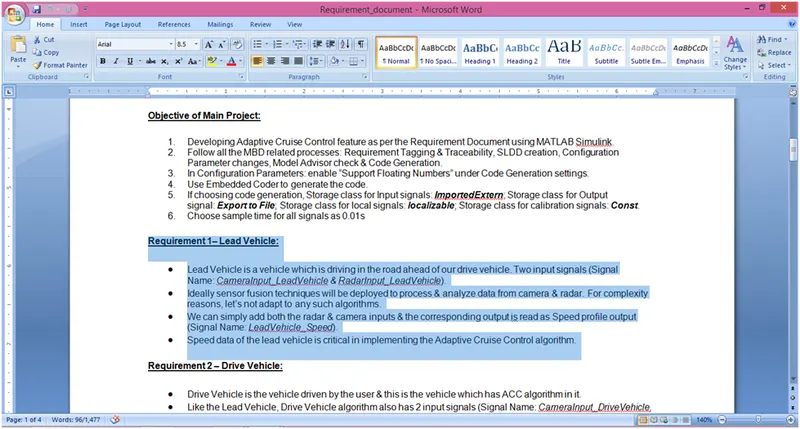
3.2 To tag requirements following procedure is adapted,
Right click on Subsystem → go to requirement → click on selection in word
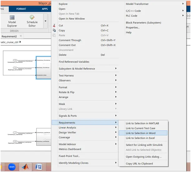
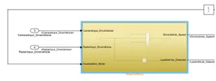
This procedure is repeated for other two requirements(subsystem).
Step 4: Signal Resolving,
4.1 Whereever signals are getting generated for the first time in the simulink model they are resolved. Following is the procedure,
Right click on signal → go to Properties → Type signal name → check the box 'Signal name must resolve to Simulink signal object' → Apply → Ok
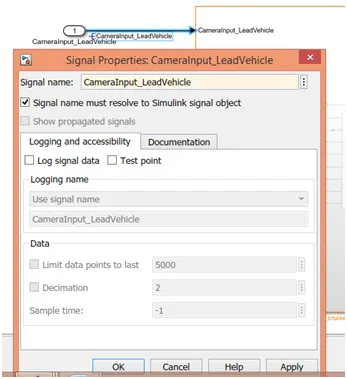
4.2 Signal are propogated by performing following procedure,
Right click on signal → go to Properties → check the box 'Show propgated signal' → Apply → Ok
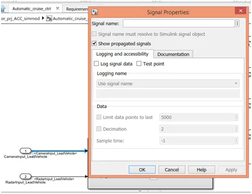
Step 5: Simulink Configuration parameters settings, perform following steps,
5.1 Click on Model Properties → In solver, type of solver is selected as Fixed-step, Solver is selected as Discrete, Fixed-step size is entered as 0.01.
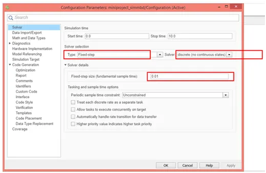
5.2
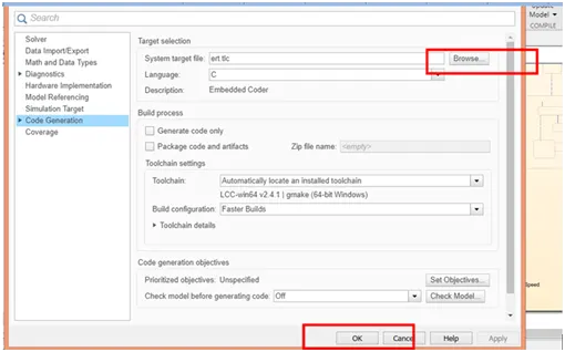
In Code generation, Click on browse → select ert.tlc Embedded coder → click on Apply → Ok.
5.3 Expand code Generation click on Interface make sure that 'floating point numbers' is checked.
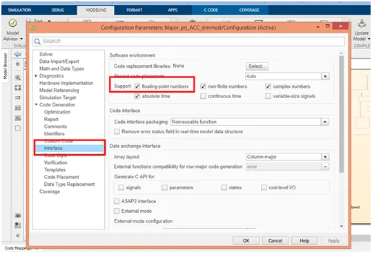
Then click on Apply and Ok.
Step 6: Model Advisory Report
To geerate model advisory report,
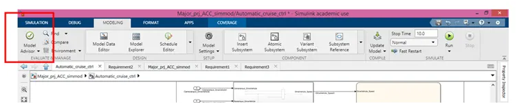
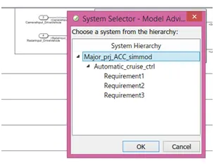
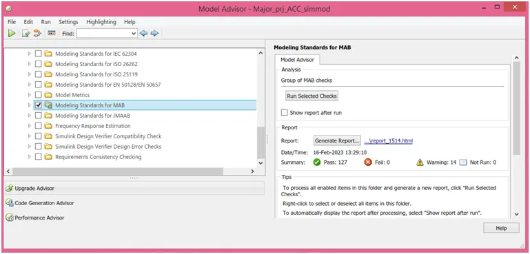
Click on Model Advisor → Select whole model (not perticular subsystem) → Ok → Uncheck all modelling standards except MAB('Modeling standard for MAB') → click on Run selected.
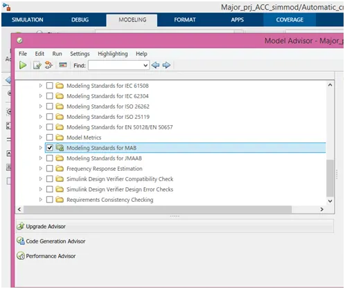
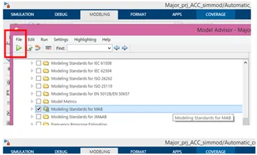
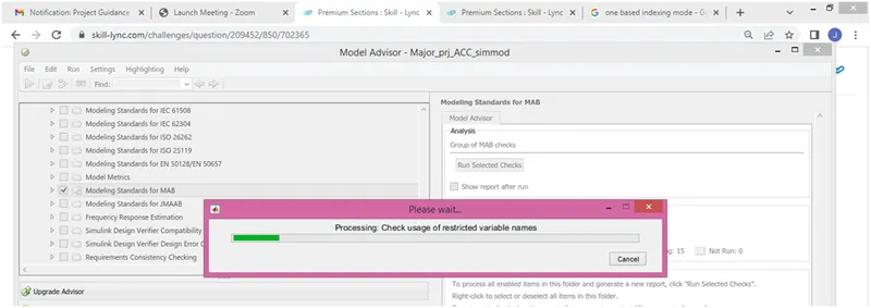
After this as per the reccommondation, change the settings and try to reduce the number of warnings.
Step 6: Code Generation
Go to Apps → Click on Embbeded Coder → Click on Build.
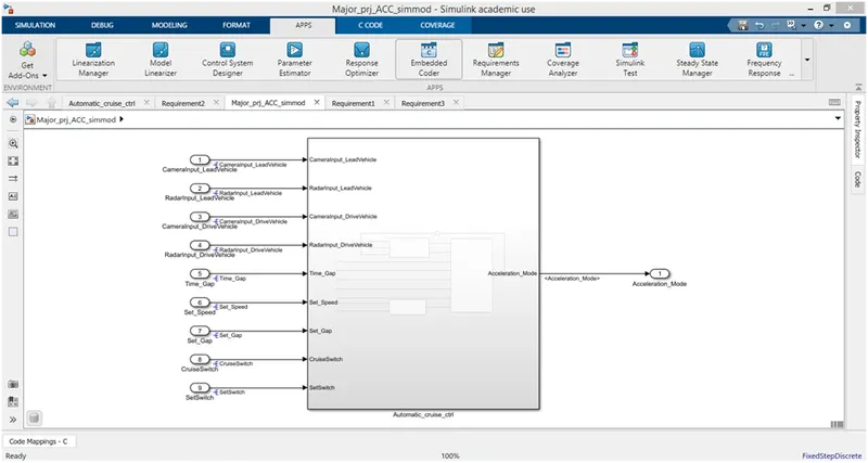

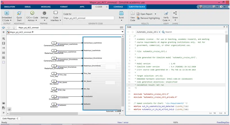
Result: Hence the Automatic cruise control feature is developed as per the requirement given. Model advisory report and Embedded code are also generated for the same.