Project 1 - Wiper control system and Vehicle speed calculation for ABS using Wheel Speed sensor
Develop the Simulink model based on the given descriptions for the below challenges and also create SLDD file and link the same to the model. Perform the complete V and V workflow for the obtained models.
- Wiper control system
Develop Simulink/state flow model for wiper control system based on the given conditions.
Description of Challenge:
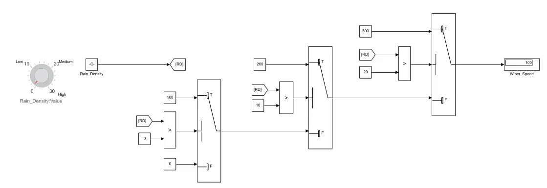
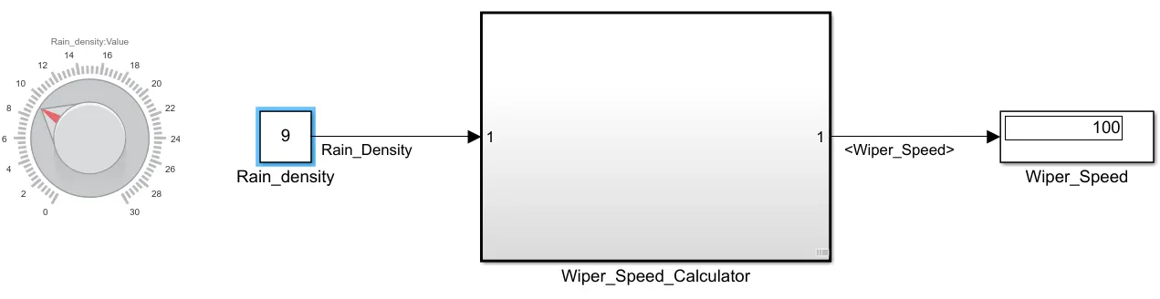
- If the density of the rain is low, then wiper rotates with low speed & the output signal should be 100rpm
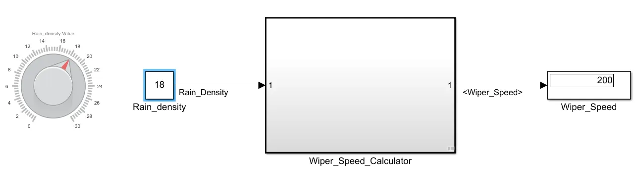
- If the density of the rain is medium, then wiper rotates with medium speed & the output signal should be 200rpm
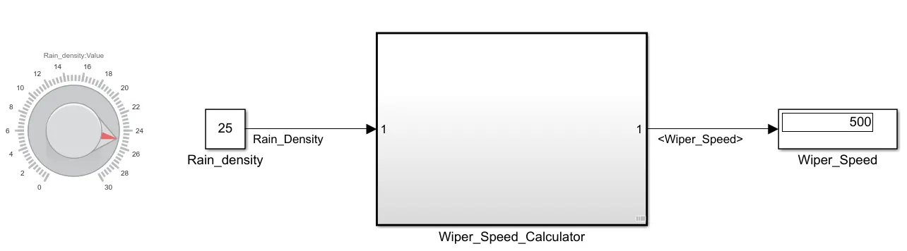
- If the density of the rain is high, then wiper rotates with high speed & the output signal should be 500rpm
Note: Rain density input comes from the external sensor, for the simulation purpose constant block with knob can be taken.
Answer:
Step1: Simulink Model :
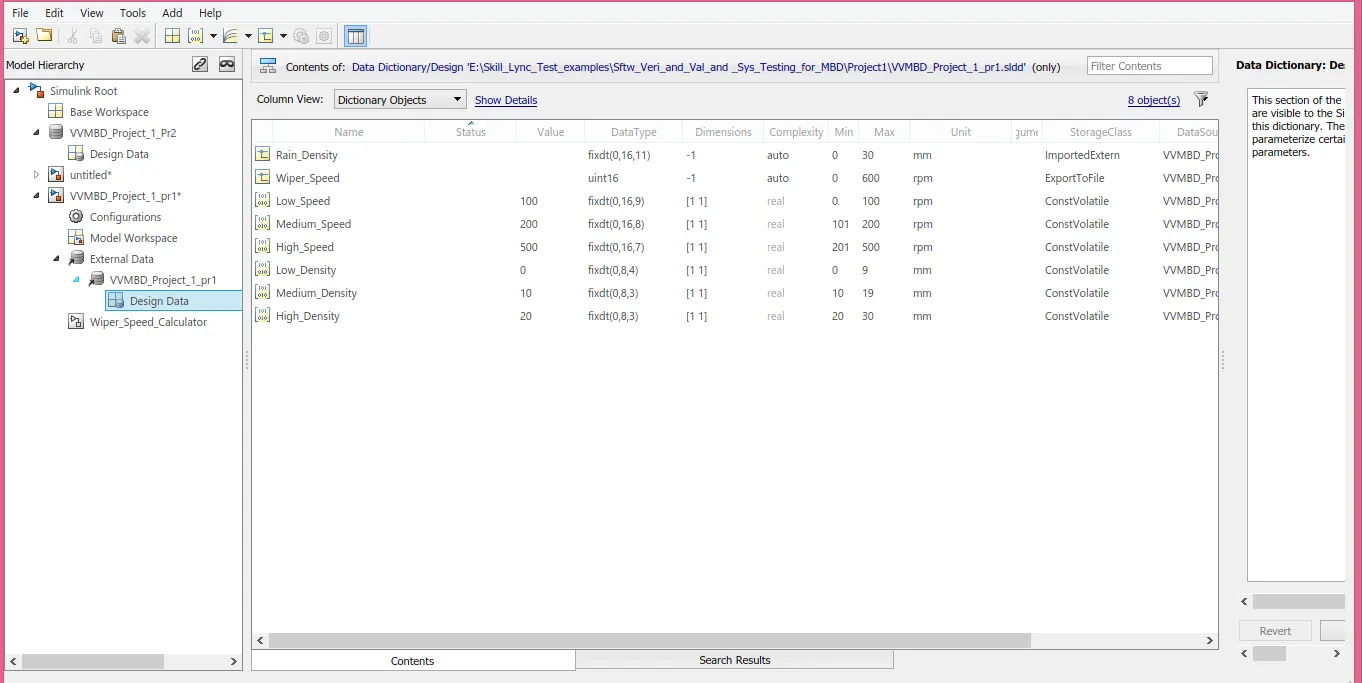
Step2.0 : .SLDD File
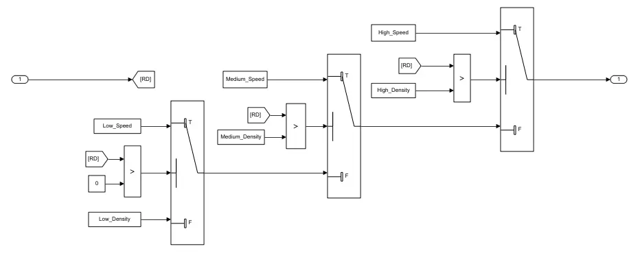
Step2.1: Model Changes as per the .SLDD file
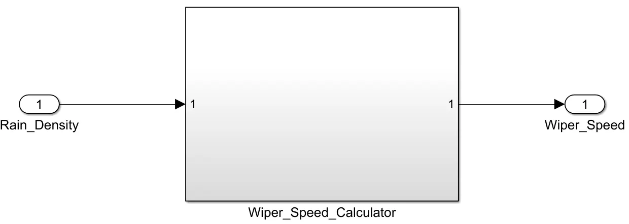
Step2.2: Creation of Subsystem
Step3.0 : Requirement Tagging and Report generation,
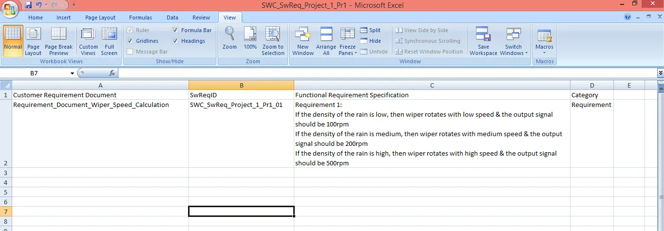
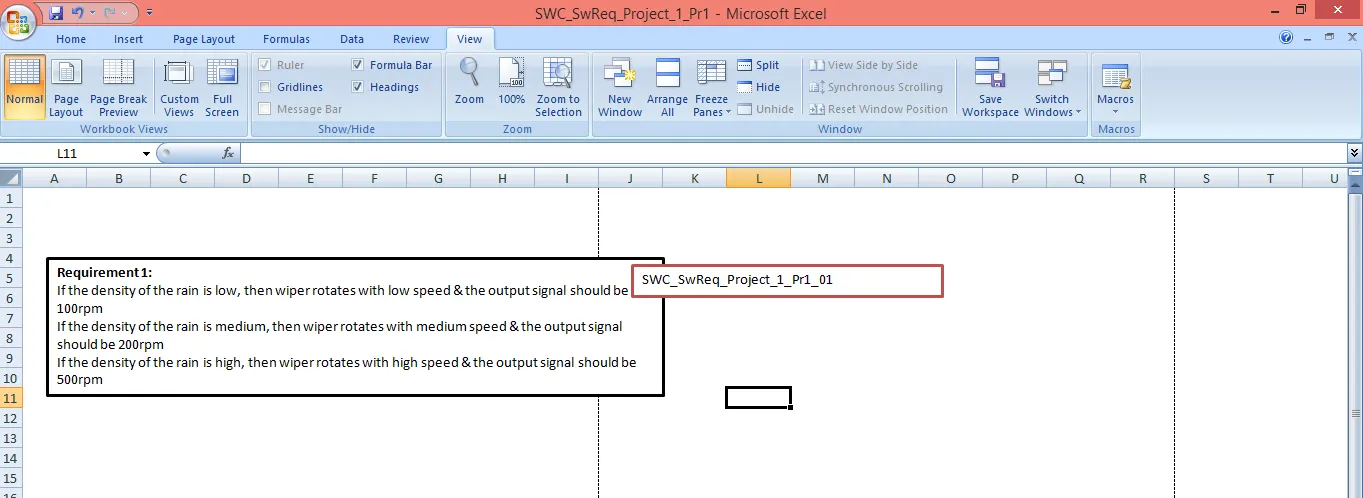
Step3.1: Generating Requirements in Requirement Editor
Go to App ---> Requirement Manager---> click on Requirement Editor ---> click on "New Requirement Set"----> Save it with proper name in working folder(.slreqx) ---> click on "Add requirement" (Add requirement in given format as shown in Figure Below)
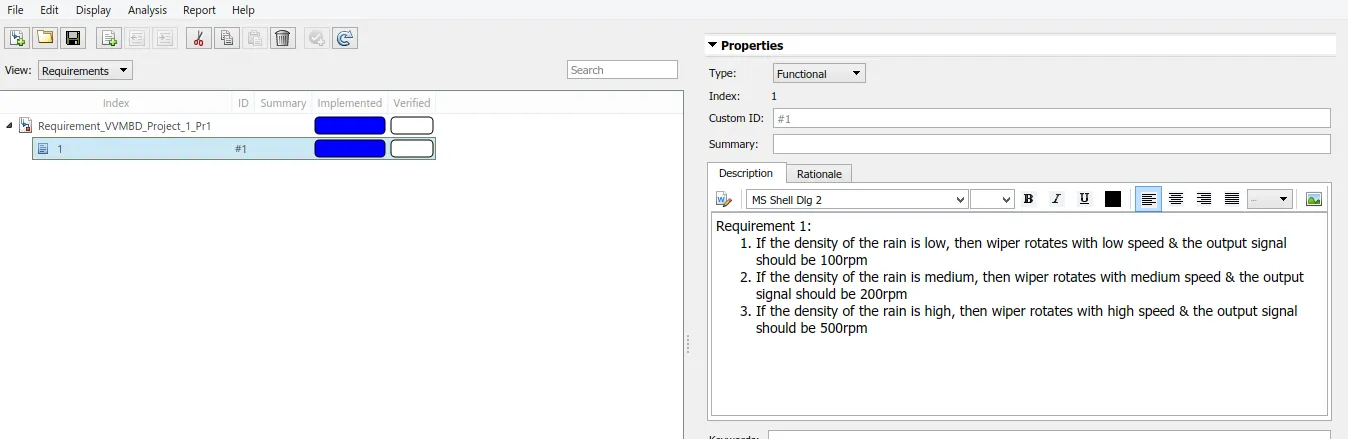
Step3.2: Linking requirement
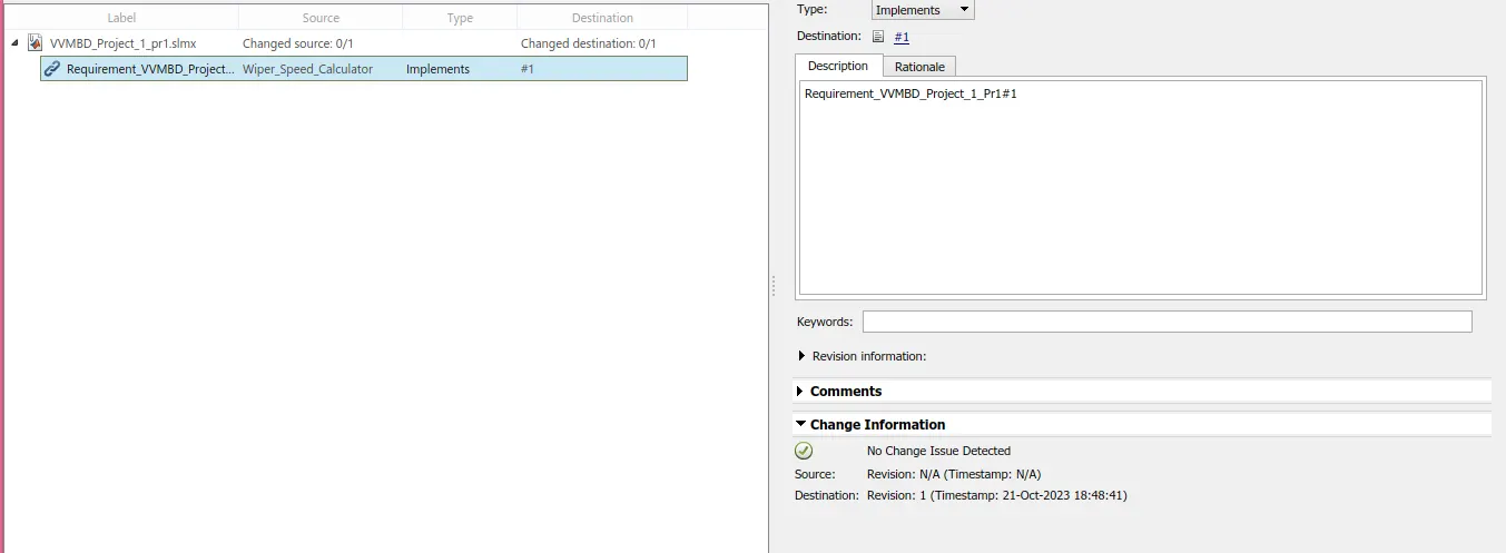
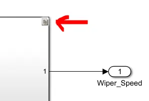
Select subsystem in Simulink Model to which requirement is to be attached ---> Go to Requirement Editor ----> Right Click on Requirement Added previously(Step3.1) ---->click on Link from "Subsystem(name)"----> go to file and click on Save all
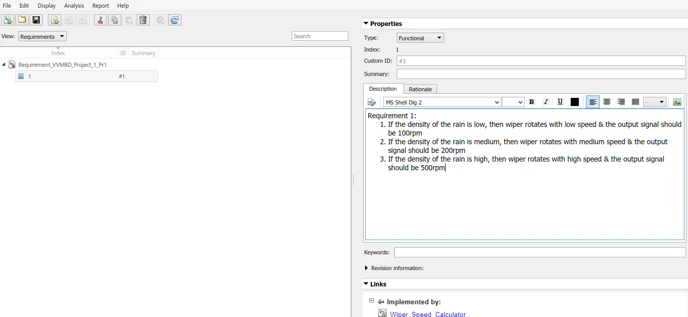
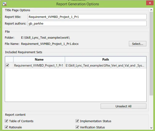
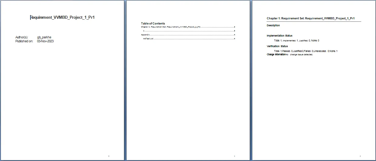
Go to Report ---->click on Generate Report ---> Do the following settings --->click on Generate Report.
Step 4.0: JMAAB Advisor Report:
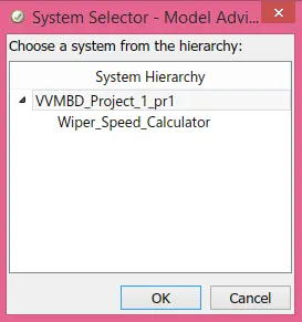
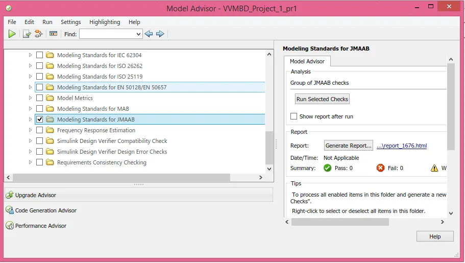
Go to Modeling--->click on Model Advisor---->Select Entire system in System Selector---->click on Ok ---> select only JMAAB guidelines in Model Advisor(All other checks are deselected) ----> Run the selected Checks

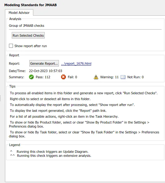
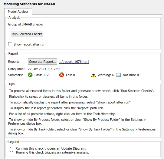
Step 4.1 Warnings are brought down to 6
Step 5.0: Fixed Point Data Tool:
Go to APPS ---> Click on Fixed Point Tool ----> Click on Drop down of "New" in tool ---> click on "Iterative Fixed Point Conversion"
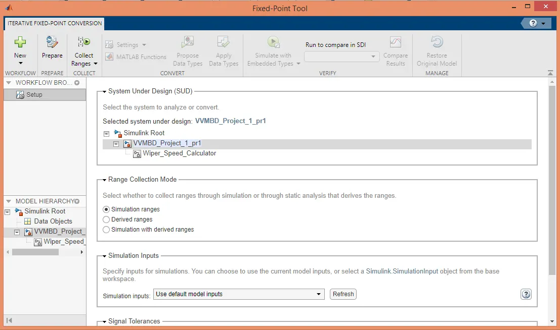
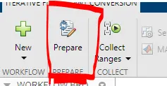
Step 5.1: Click on "Prepare"
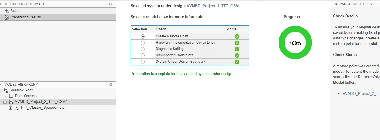
Step 5.2: Click on Drop down of "Collect Ranges"---> Select default settings as "Use Current Settings" ---> click on "Collect Ranges" .
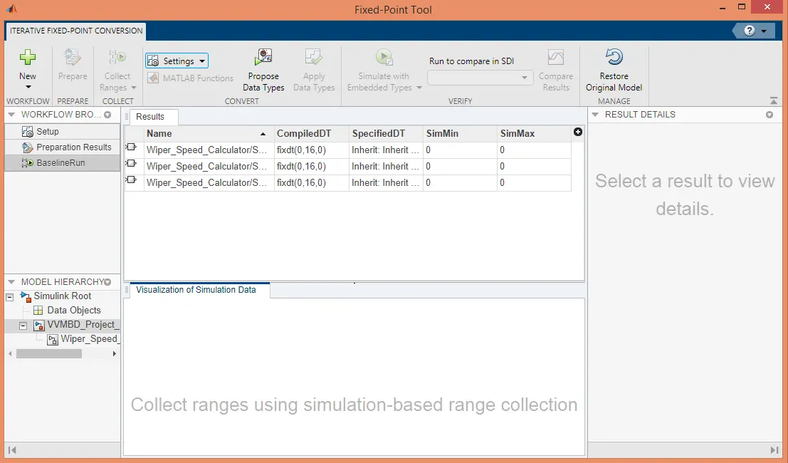
Step 5.3 : Click on "Propose Data Type". The proposed data types will look like,
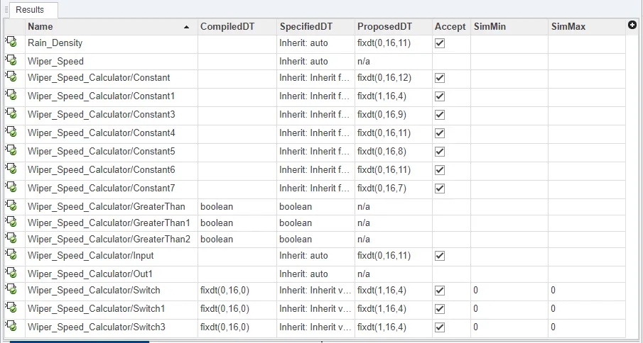
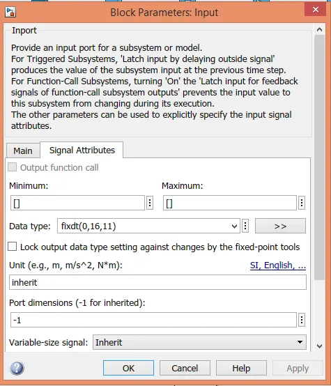
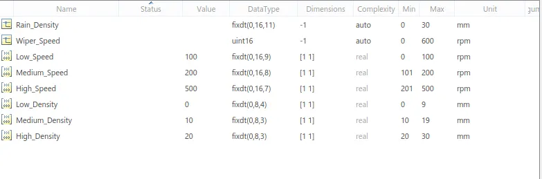
Step 5.4 : Click on "Apply Data type". Check the data types changes at model level and in .SLDD file.
Also, Simulate model for to ensure these changes does not hamper execution of model.
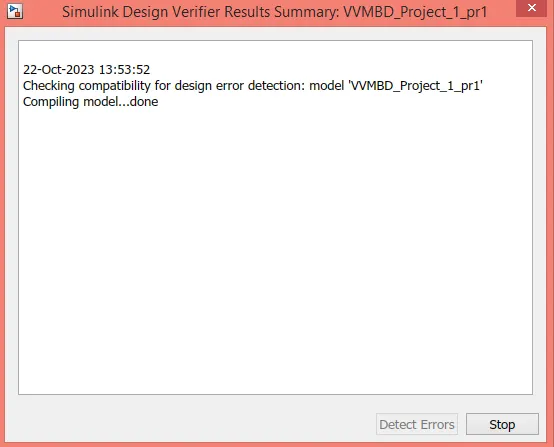
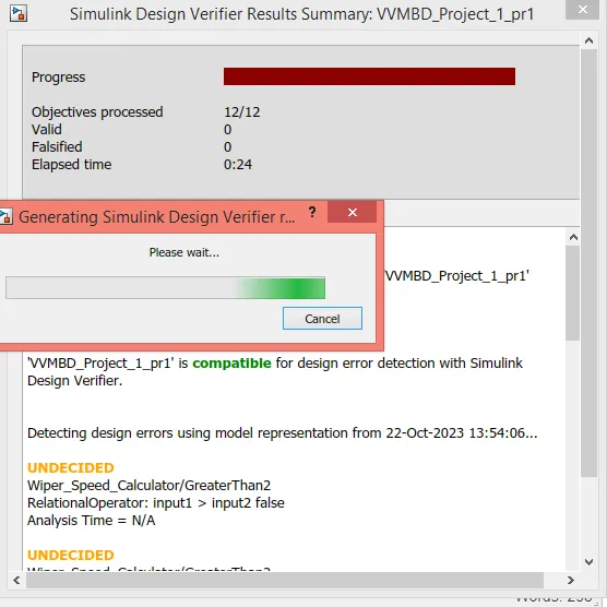
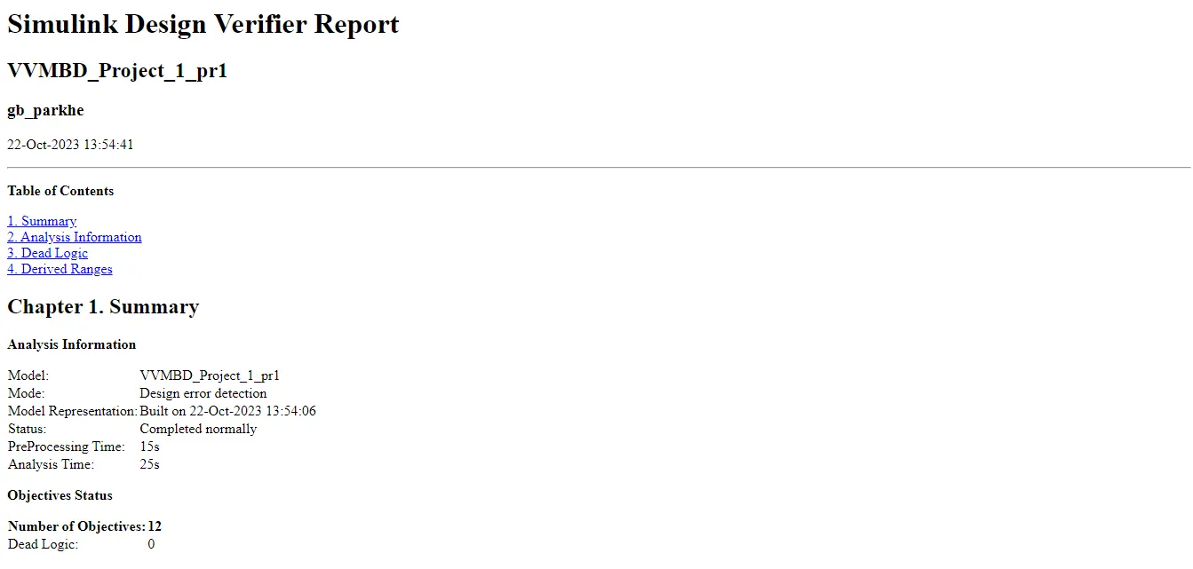
Step 6.0 : Design Error Detection:
Go to APPS ---> Click on "Design Verifier" ---> Click on Drop Down of "Test Generation Tab" and select Error Detection.

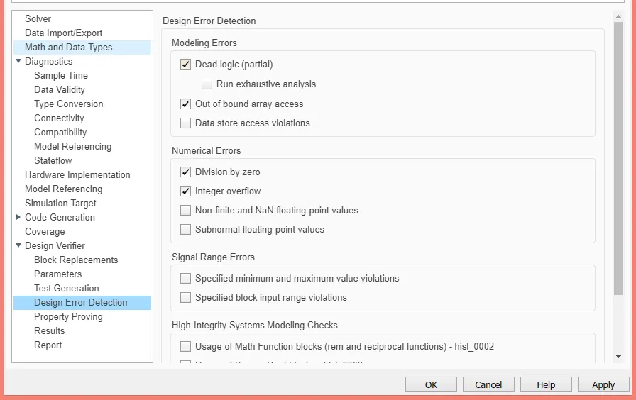
Step 6.1 : Click on Error Detection Setting ---> Do the following settings in it. click on Ok
Step 6.2: Click on Run Tab to run the error detection,
Step 7.0: For Test Generation,
Go to APPS ---> Click on "Design Verifier" ---> Click on "Advisor"
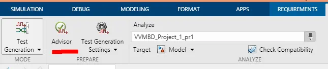
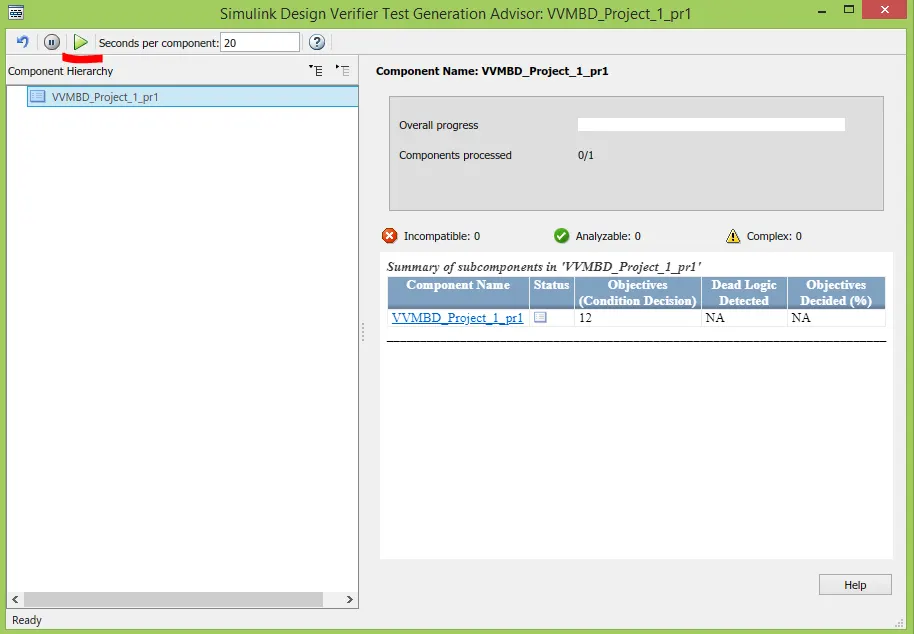
Step 7.1: Click Test Generation Advisor's Run tab shown in above figure,
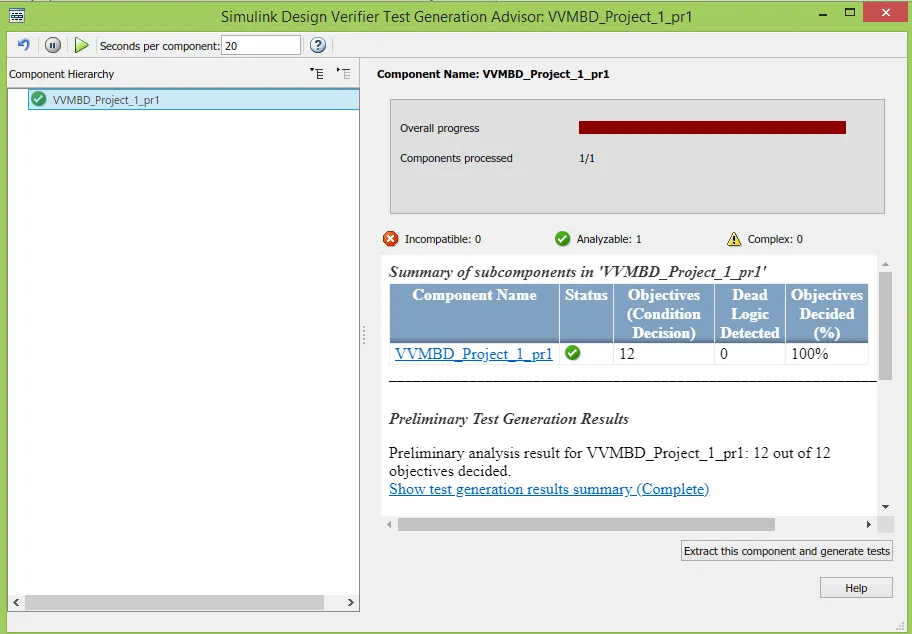
Step 7.2: Now, click on Run tab of Test Generator,
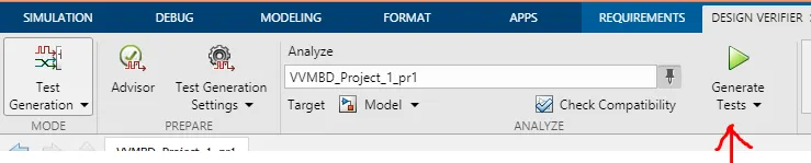
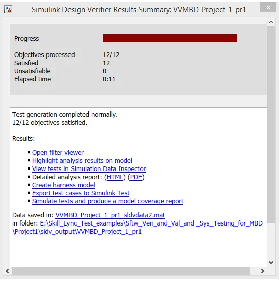
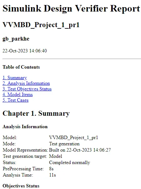
Step 8.0: Functional Tests,
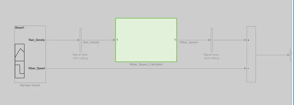
Step8.1 : MIL Test Harness Creation, test cases generation
Right click on Main Subsystem ---> click on "Test Harness" ---> click on "Subsystem name" ---> do the following settings
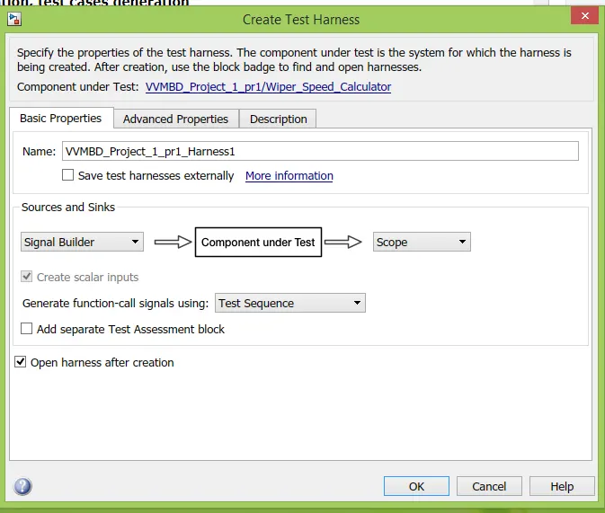
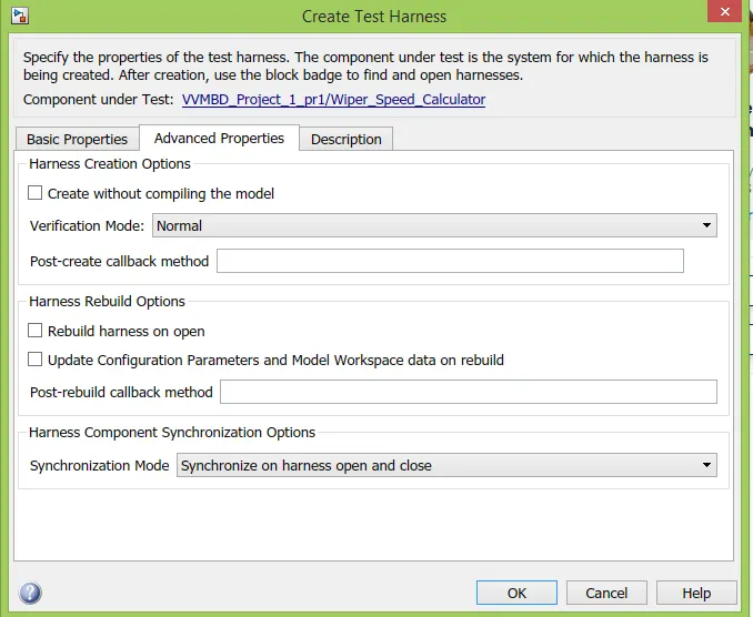
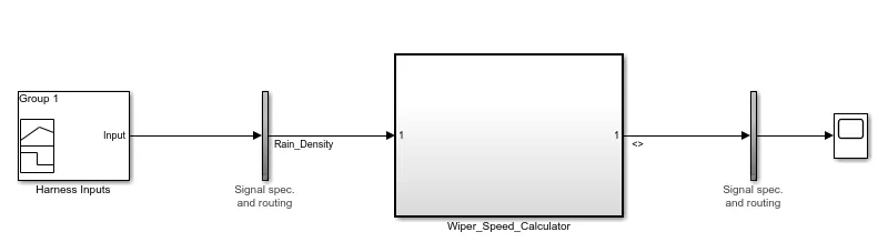
Step 8.2: Test Creation
.xls file
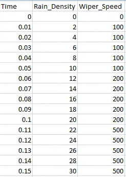
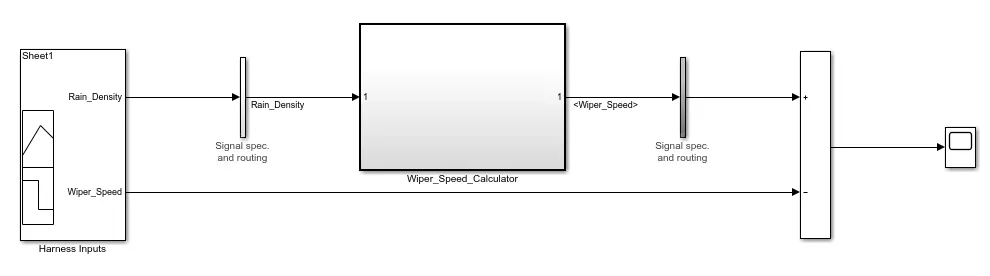
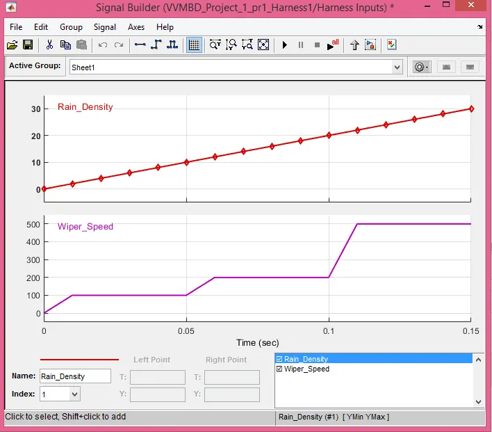
Step 8.3: Importing Test Cases in Signal Builder,
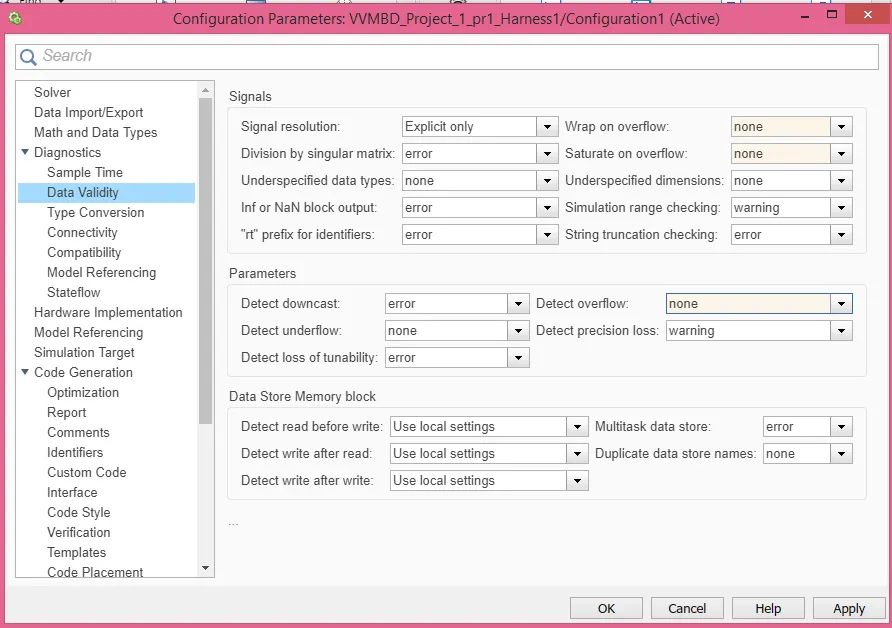
Step 8.4: Settings in Model configurations,
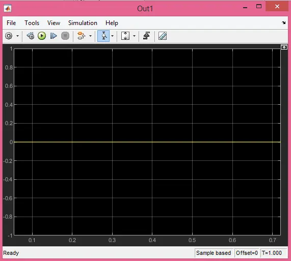
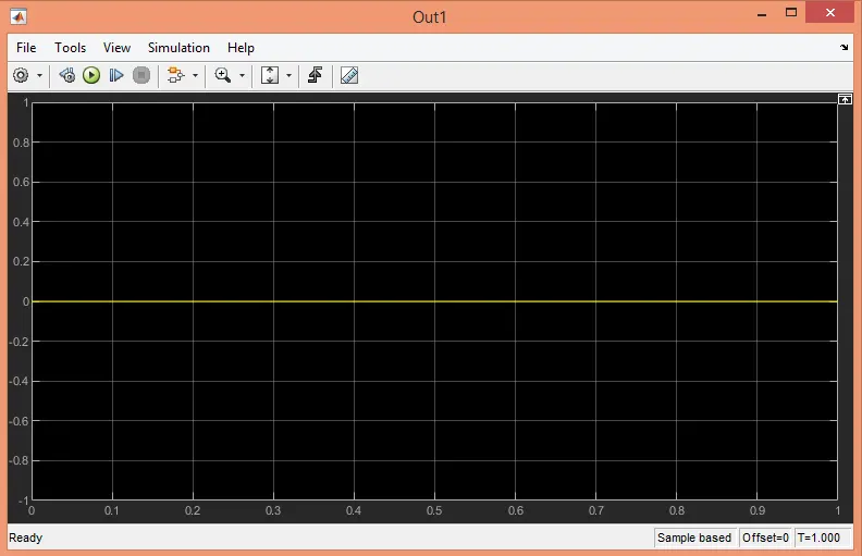
Scope Output:
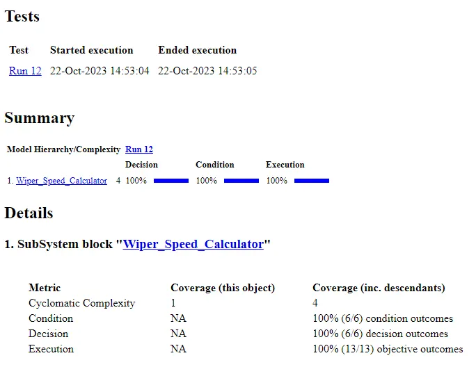
Step 8.5: MCDC Coverage:
Step 8.6: SIL Test Harness Creation, test cases generation
Right click on Main Subsystem ---> click on "Test Harness" ---> click on "Subsystem name" ---> do the following settings
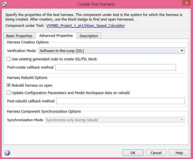
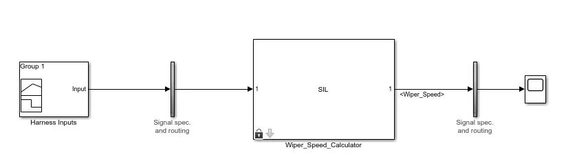
Step 8.7: Add test case to signal builder(Same as that of MIL test)
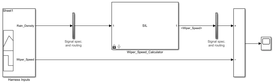
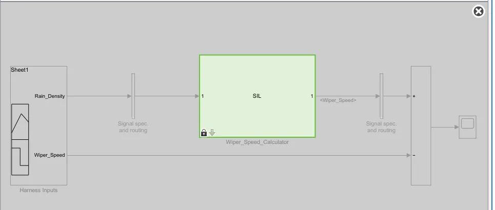
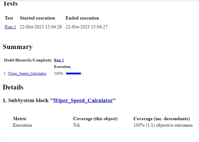
Step 9.0: Auto Code Generation:
Go to Apps ---> click on Embedded Coder ---> click on "Build"(Ensure the setting ert.tlc in code generation)

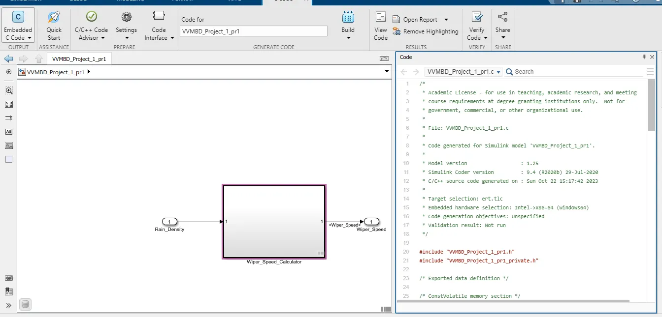
Step 10. Poly space analysis report / outputs
Step 10: Polyspace
Step10.1: Go to Polyspace ---> Click on Start New Project ---> Provide Project Name ---> click on "Next"---> provide Project Source File(where .c files are generated during Auto Code Generation)--->click on "Finish"
Step 10.2: Different Settings in Polyspace Environment
In Target & Compiler ---> select Target processor type as "x86_64"
In Coding standards and Coding Matrics---> MISRA C:2004(Selected) Required Rules --->Calculate code matrics(Selected)
In Bugfinder Analysis default settings are selected.
In Reporting ---> Generate Report(selected)--->Output Format PDF(Selected)
Step 10.3 :Save by clicking on Save tab
Step 10.4: Run the polyspace bug finder
**************************************************************************
Polyspace Code Prover:
Steps to Run the Code Prover:
Step 10.5: Go to Polyspace Environment
Go to Configuration --->Environment Settings ---> Stop analysis if file not compile(Selected)
In Code Prover Verfication ---> Check Behavior ---> Allow Negative Operand for left shift(Selected) --->Consider non finite float(Selected)
Step 10.6: Save by clicking on Save tab
Step10.7: Run Code Prover by clicking on drop down menu of Run Tab
Step 11.0 : Baseline Testing
Step 11.1: Go to APP ---> Click on Simulnik Test, Simulink Test Manager tool box will appear as follows, click on Simulink Test Manager

Step 11.2: Click on 'New' ---> Test File. Save it in working folder. The extension of file is ".mldatx" Go to APP ---> Click on Simulnik Test, Simulink Test Manager tool box will appear as follows, click on Simulink Test Manager
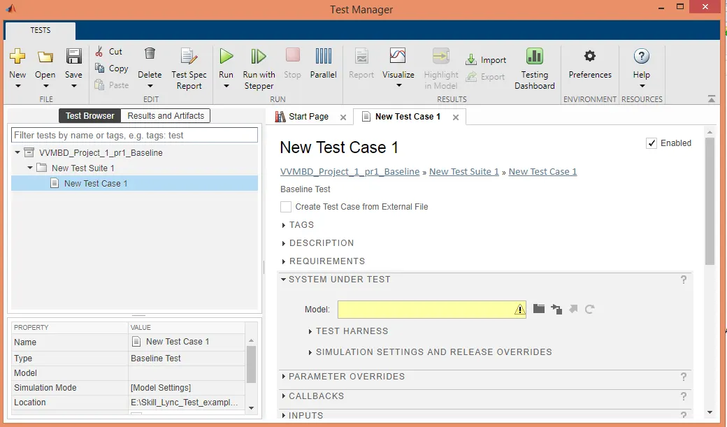
Requirements Now do the following settings
Step 11.3: Go to Requirements ---> click on +Add ---> Click on New, Select document type "Requirement Set" --->Browse for .slreqx file --->Go to Document index and select particular Requirement ID ---->Click on Apply and Ok , the requirement will get updated under REQUIREMENTS tab.
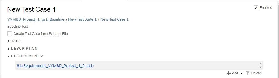
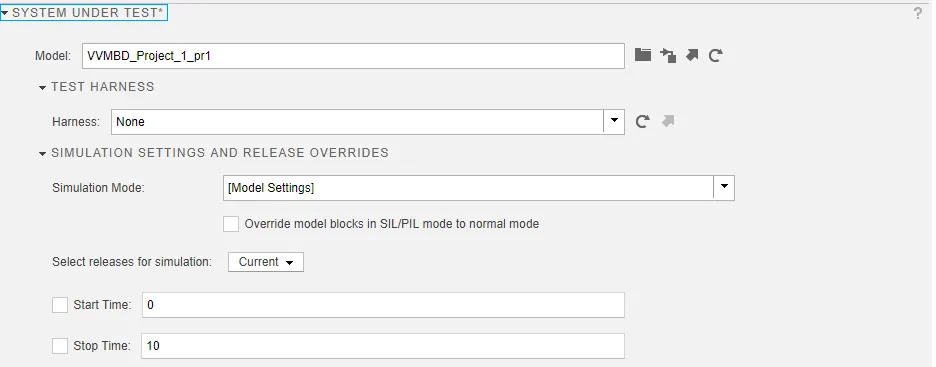
Step 11.4: Go to System under test, Browse for model to be tested, add harness if any or leave it as None.
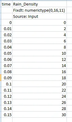
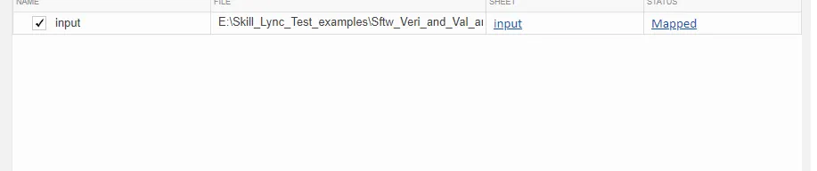
Step 11.5: Go to INPUT, click on create. Select File Format as EXCEL, select working folder and save the file with appropriate name---->click on Create.
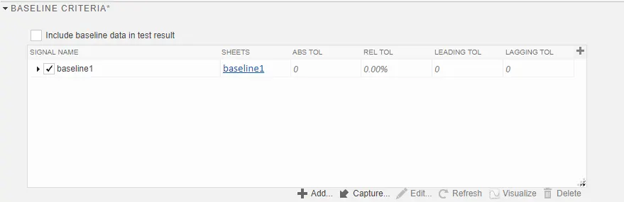
Step 11.6: Go to Baseline Criteria, click on capture ---->Save it with specific name.
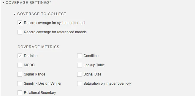
Step 11.7: Go to Coverage --> check "Record coverage for system under test"---> click on Enable Coverage
Save settings,
Step 11.8: Now click on Run Tab
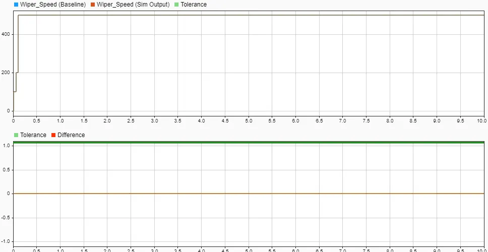
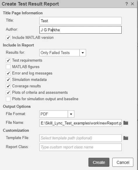
Step 11.9: To generate report click on Create ----> do the following settings
Click on Create
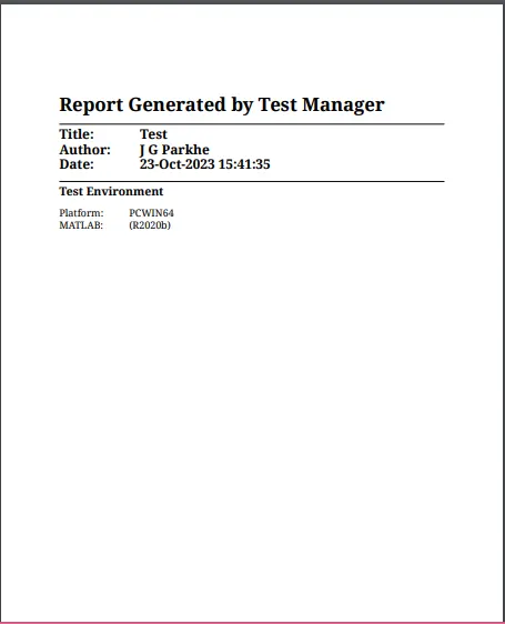
Step 11.10: Report will be generated in .PDF format (attached herewith).
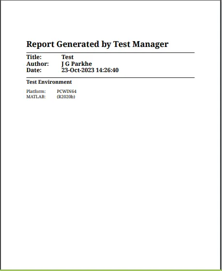
Step 12: Back To Back Test:
Step 12.1: Go to Simulink test Manager ---> Click on Simulnik Test Manager
Step12.2 : Click on "New" ---> Click on "Test File"
Step 12.3: Do the following Settings,
Step 12.4 : Delete the test suits added first
Step 12.5 : Click on New----> Test for Model Component
Step 12.6 : Before Doing this go to top level of Model and select the main subsystem(Keep it like this only).
Then Do the following in Test for Model Component window
select the model by browsing under "Top Model"
under Component just click on Icon pointed in figure to select Model's top level subsystem selected in Simulink model prior( in Step 12.6).
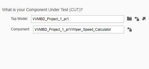
Click on Next
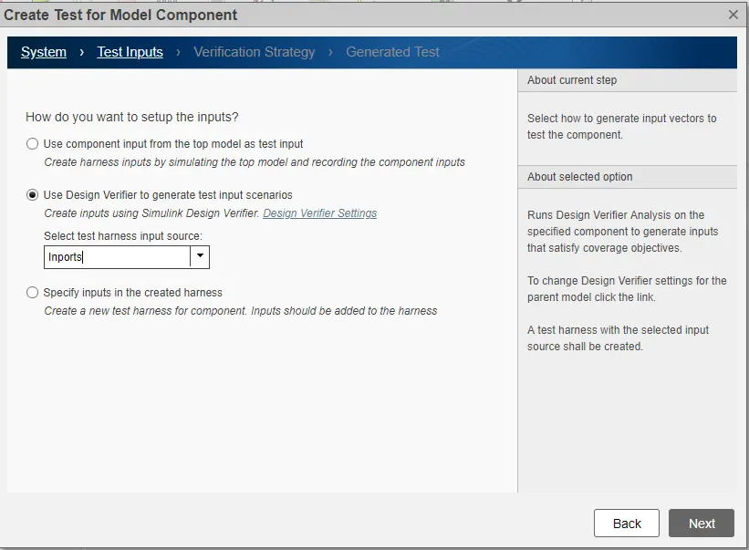
Select the following settings and click on Next.
Make sure that your main subsystem should be Atomic Subsystem
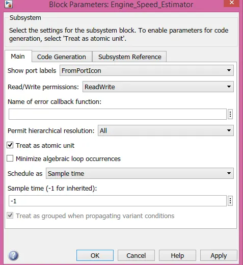
Do the following settings and click on Next,
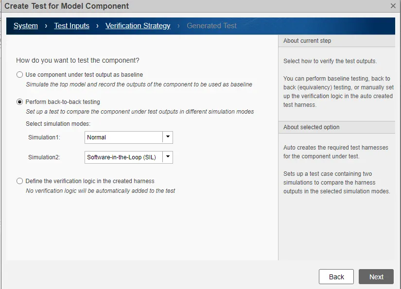
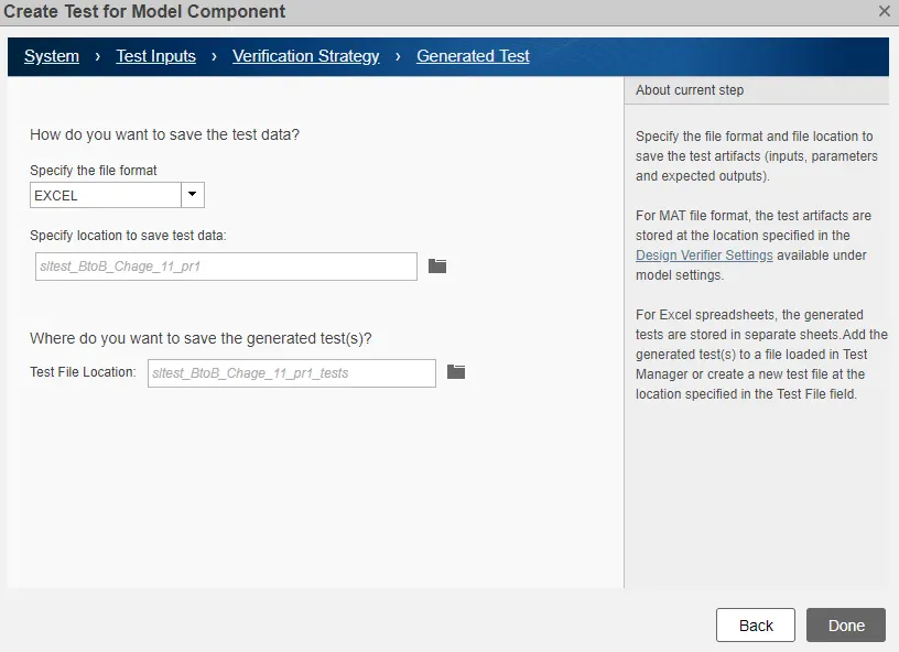
Click on Done
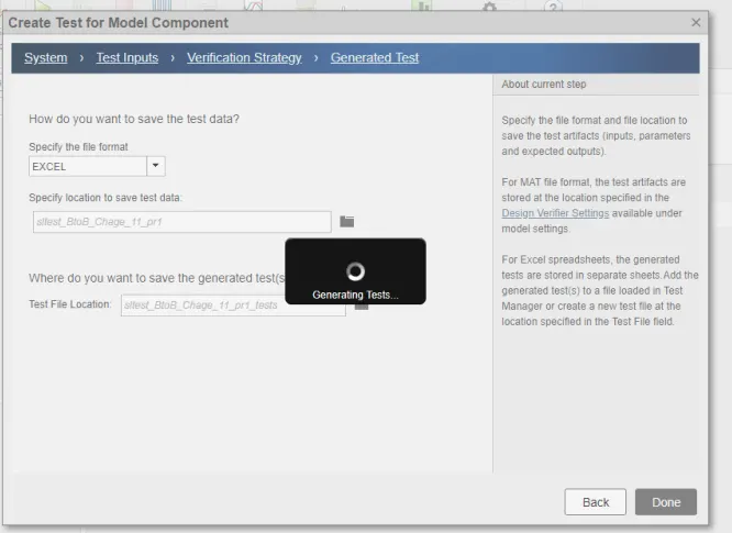
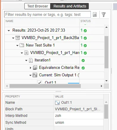
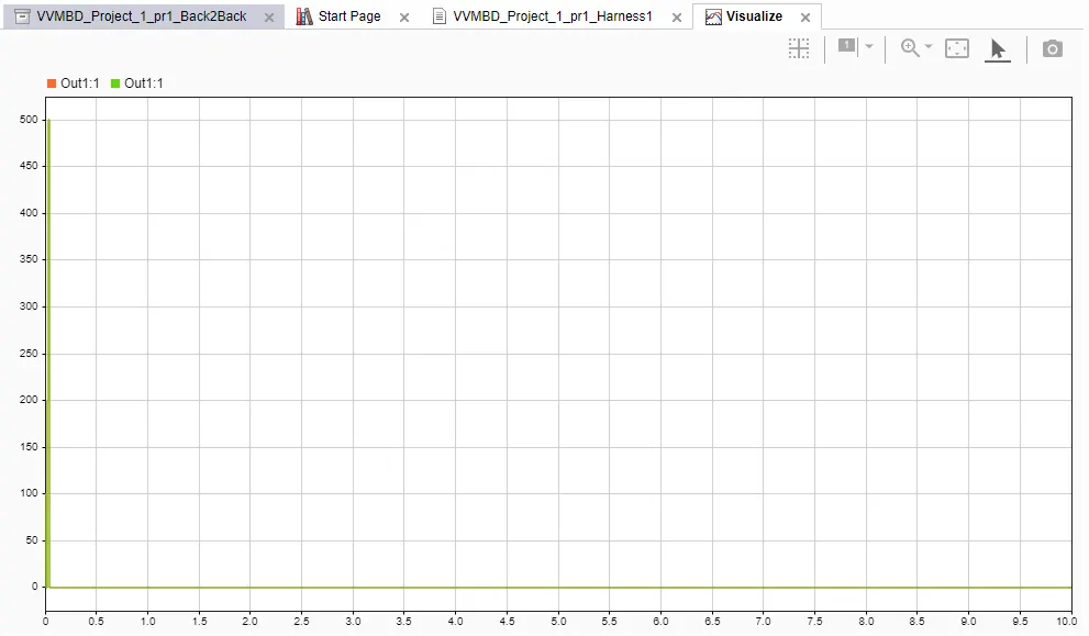
Test harnesses, design verifier report will get generated,
Step 13.0 : Output:
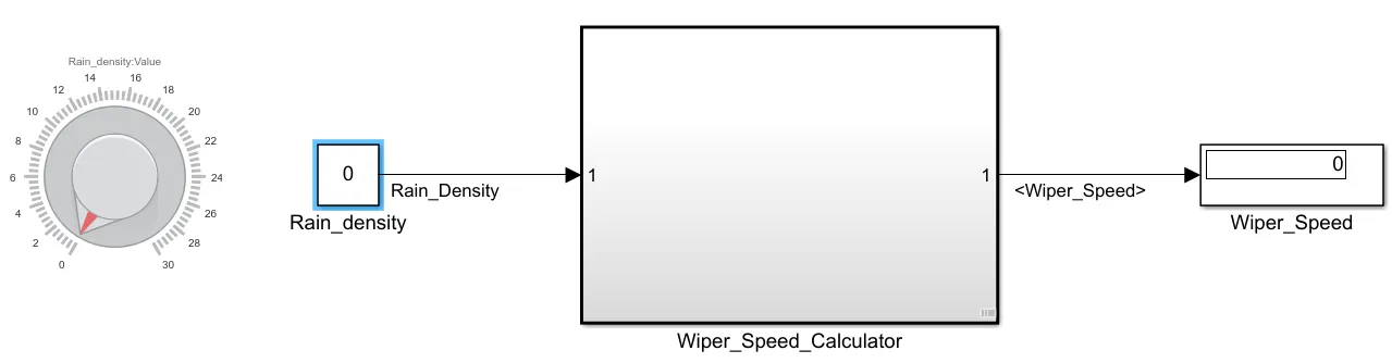
1) When No Rain (Rain_Density =0)
2) Low Rain_Density(0<Rain_Density>11)
3) Medium Rain_Density(10<Rain_Density>21)
4) High Rain_Density(Rain_Density>21)
Conclusion:
The Simulink model created for Wiper control is working as per expectations.
The rigorous assessment of model is carried out using different tools in MATLAB such as
· Requirement tagging
· Model advisor - JMAAB compliance
· Fixed-point Tool
· SLDV Design error detection report
· Functional test case, MIL, SIL harness
· SLDV test generation
· Auto-code generation, main , .c & .h files
· Poly space analysis
· Test manager – baseline & back-to-back testing
The reports for each task is generated and attached herewith(VVMBD_Prj1_pr1.zip).
**************************************************************************
2.Vehicle speed calculation for ABS using Wheel Speed sensor
Develop Simulink/state flow model for the vehicle speed calculation unit inside the ABS system for the below conditions.
Description of Challenge:
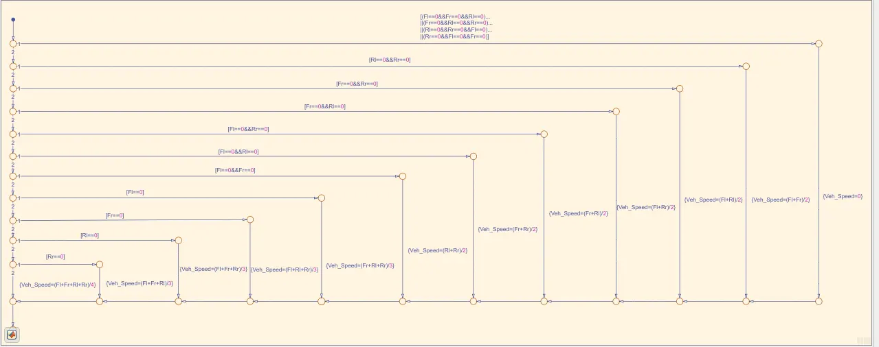
fl, fr, rl and rr are the wheel speeds of front left, front right, rear left and rear right respectively.
Answer:
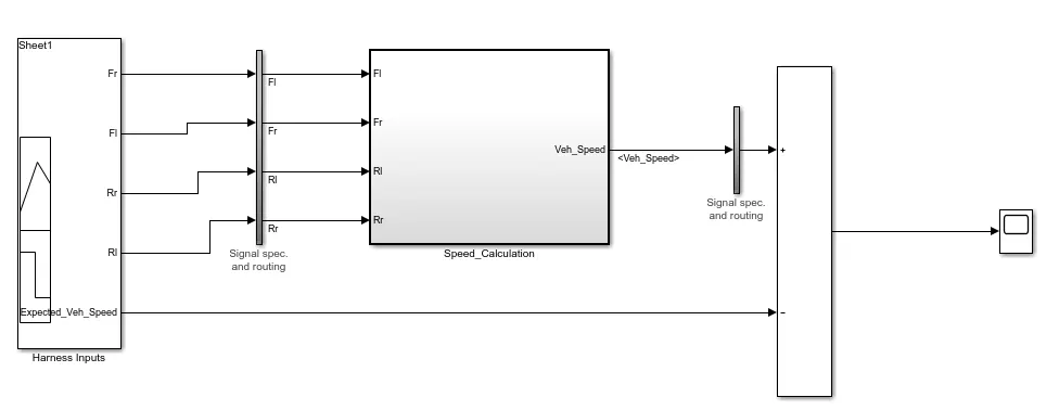
Step1: Simulink Model :
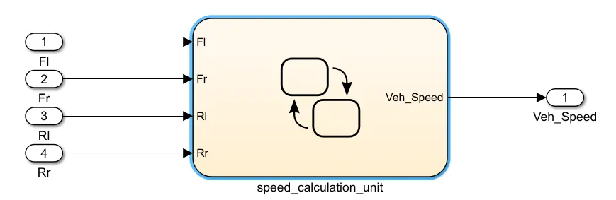
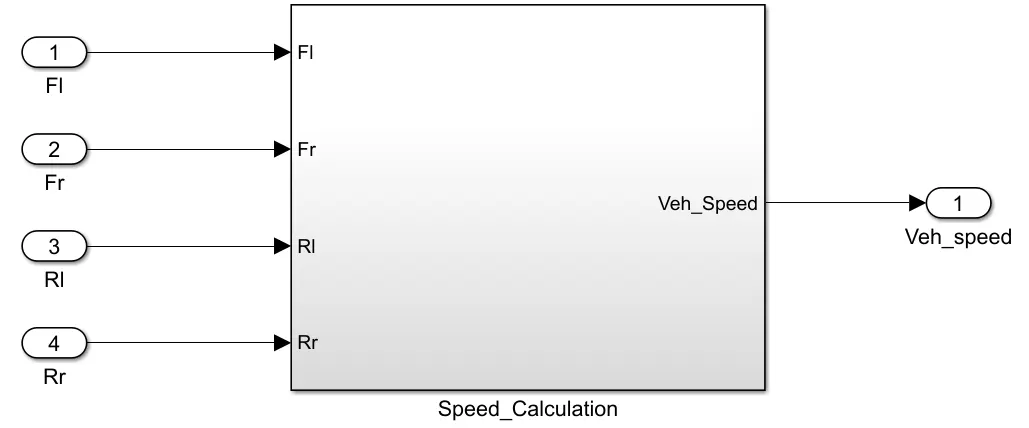
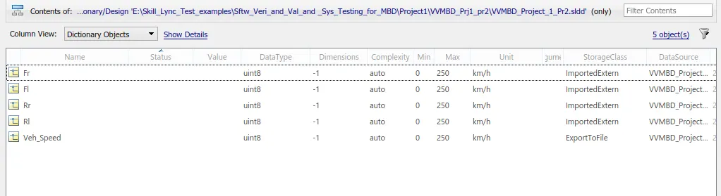
Step 2: .SLDD File
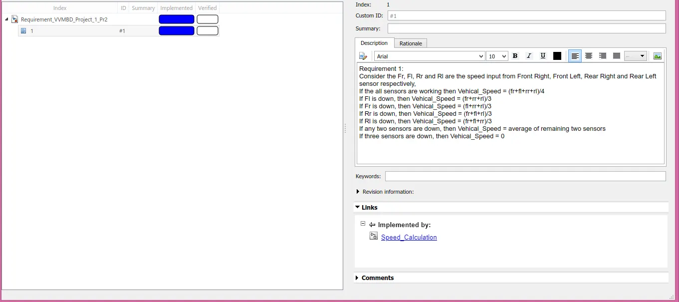
Step 3: Requirement Document tagging and linking
Step 4: Model Advisor JMAAB Report:
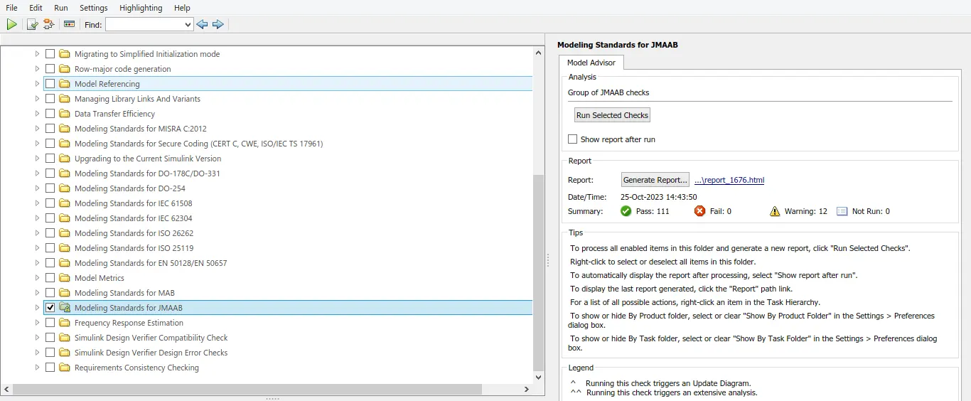
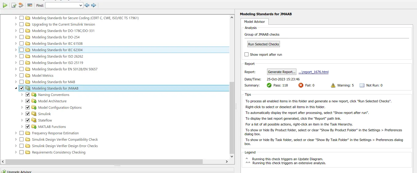
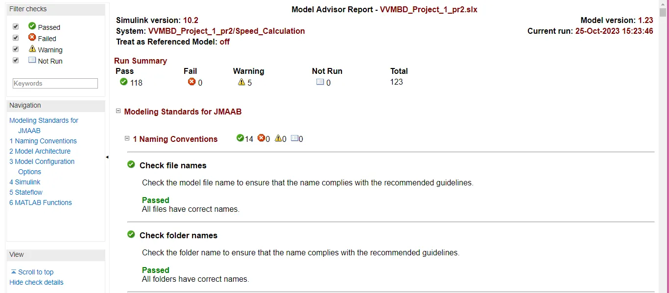
Warnings are reduced to 5 by applying recommended.
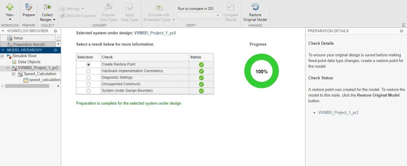
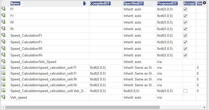
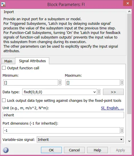
Step 5: Fixed Point Tool Bar:
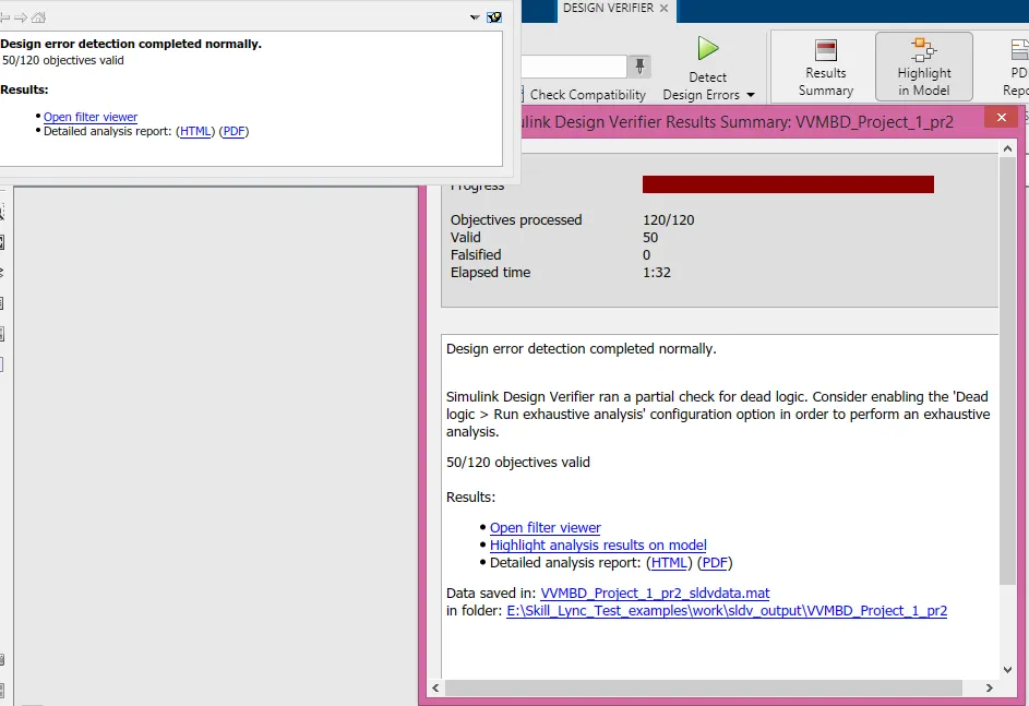
Step 6.0 : Design Error Detection:
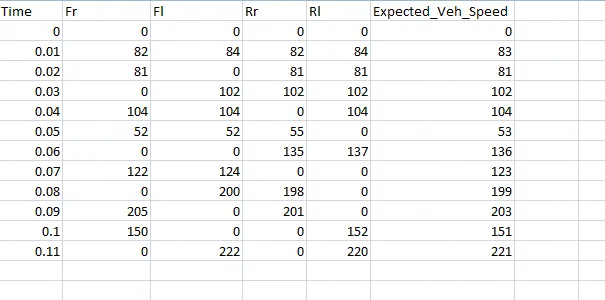
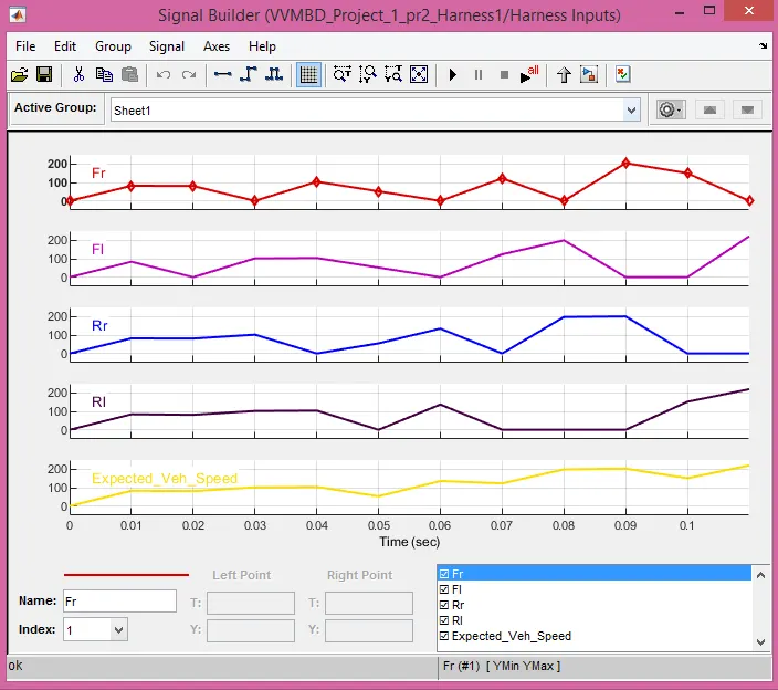
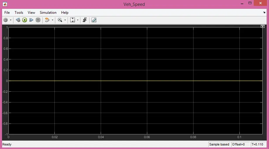
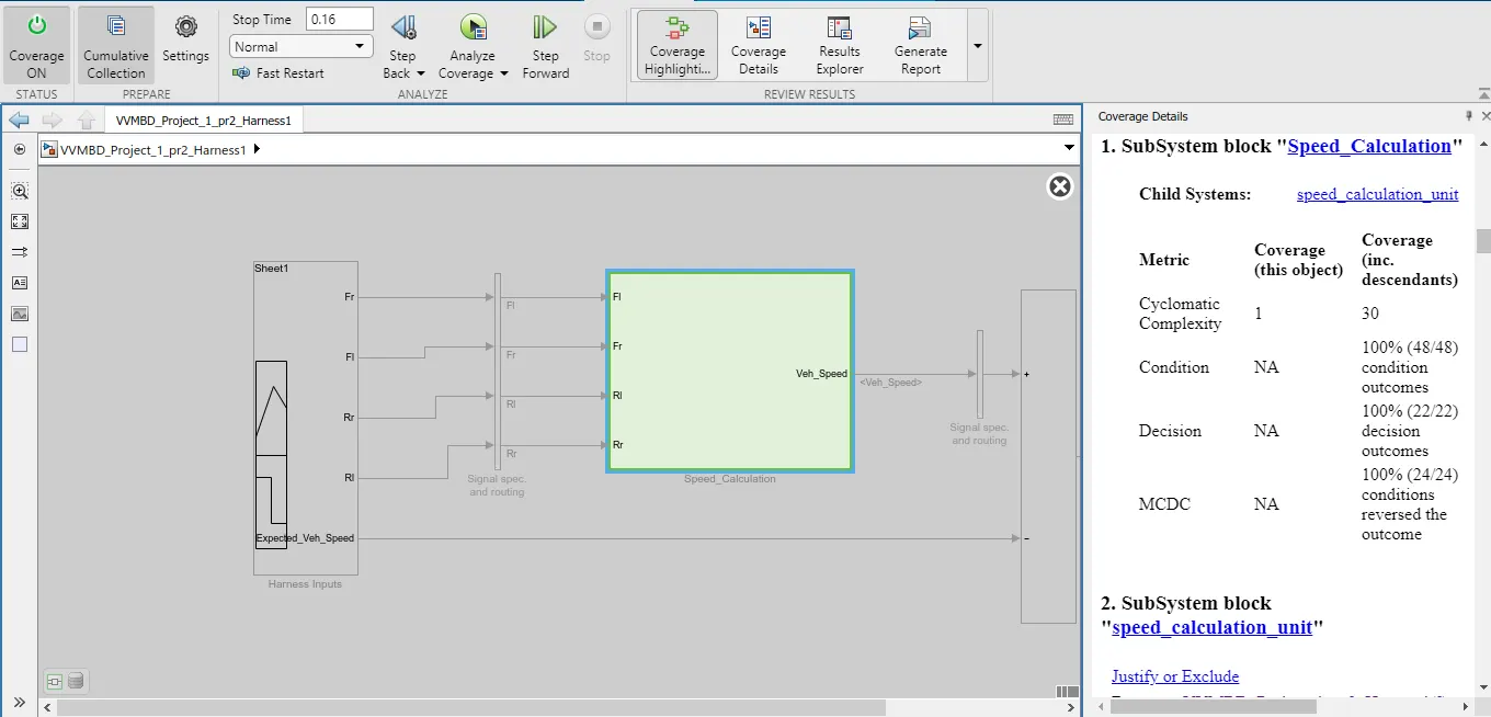
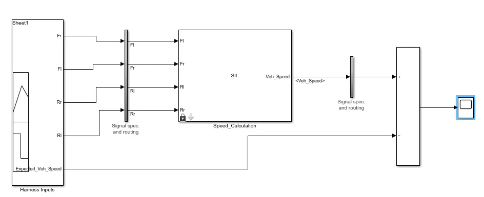
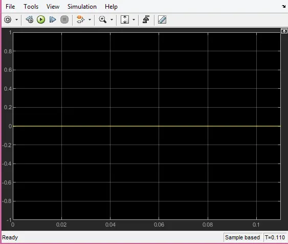
Step 7: Functional Tests, MIL, SIL, Coverage Analysis.
MIL
SIL
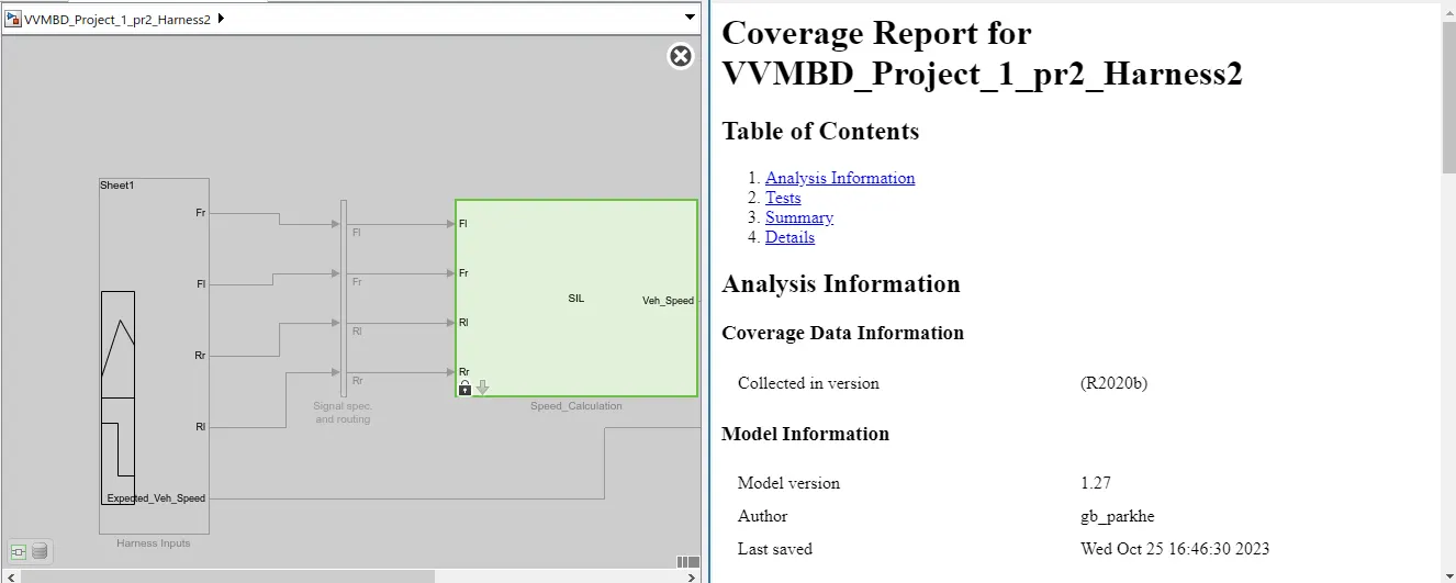
MIL Step 8: SLDV test generation report,
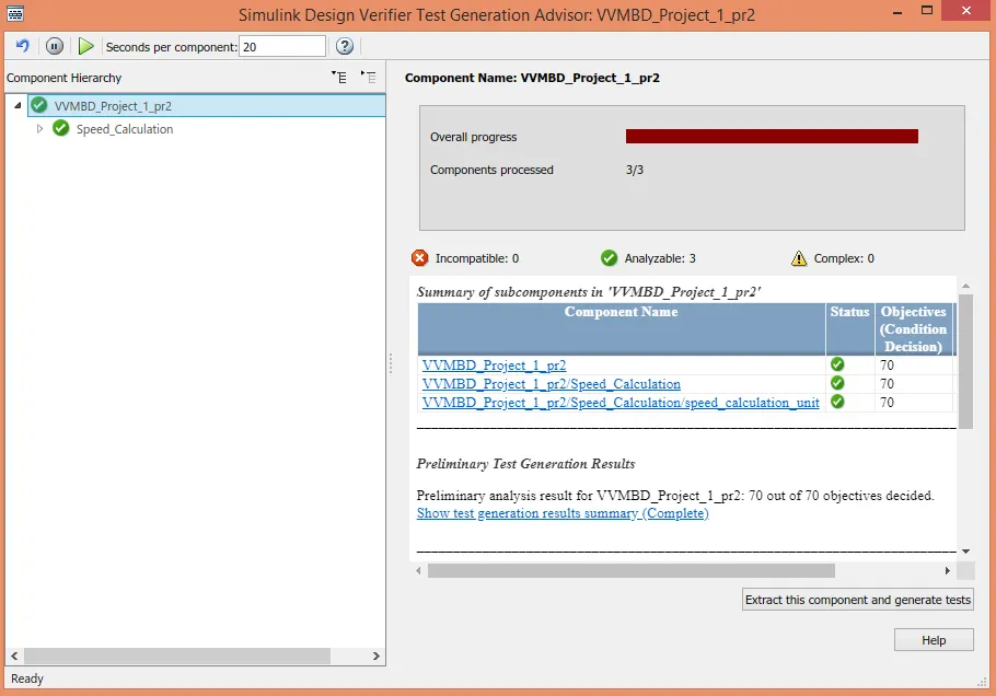
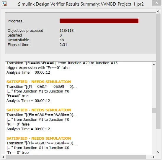
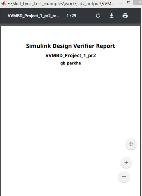
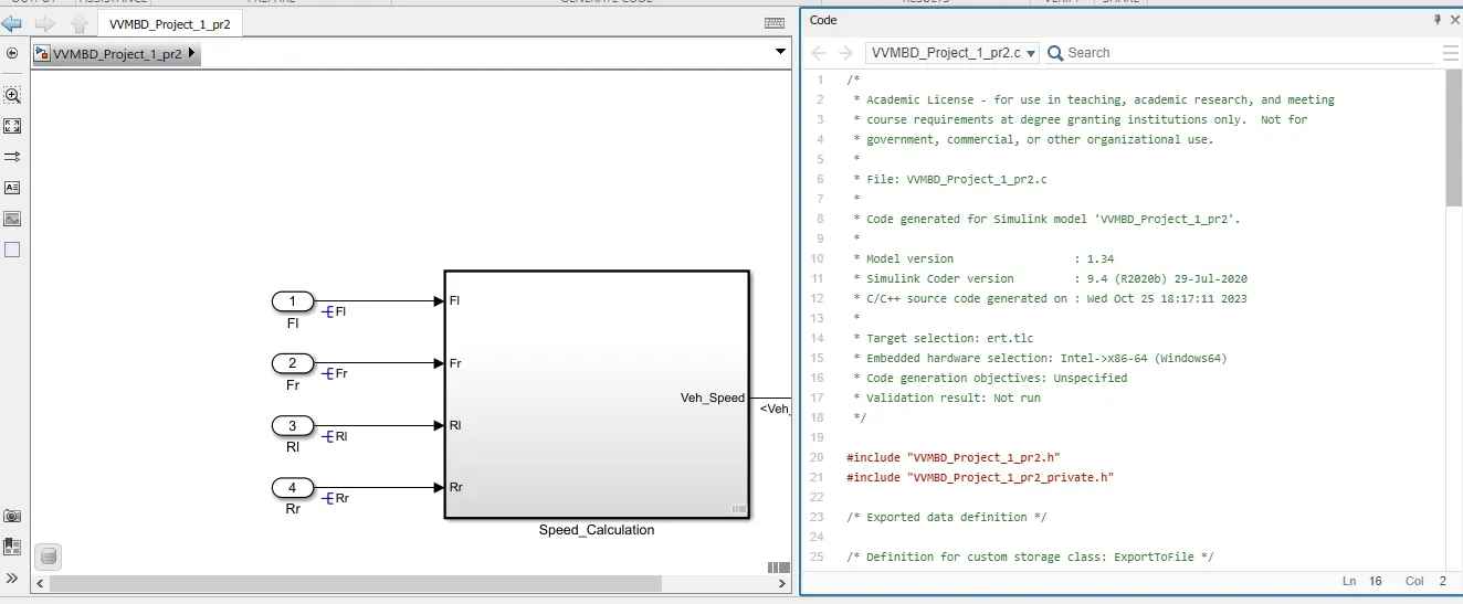
Autocode Generation:
Step 10. Poly space analysis report / outputs
Step 10: Polyspace
Step10.1: Go to Polyspace ---> Click on Start New Project ---> Provide Project Name ---> click on "Next"---> provide Project Source File(where .c files are generated during Auto Code Generation)--->click on "Finish"
Step 10.2: Different Settings in Polyspace Environment
In Target & Compiler ---> select Target processor type as "x86_64"
In Coding standards and Coding Metrics---> MISRA C:2004(Selected) Required Rules --->Calculate code metrics(Selected)
In Bugfinder Analysis default settings are selected.
In Reporting ---> Generate Report(selected)--->Output Format PDF(Selected)
Step 10.3 :Save by clicking on Save tab
Step 10.4: Run the polyspace bug finder
**************************************************************************
Polyspace Code Prover:
Steps to Run the Code Prover:
Step 10.5: Go to Polyspace Environment
Go to Configuration --->Environment Settings ---> Stop analysis if file not compile(Selected)
In Code Prover Verfication ---> Check Behavior ---> Allow Negative Operand for left shift(Selected) --->Consider non finite float(Selected)
Step 10.6: Save by clicking on Save tab
Step10.7: Run Code Prover by clicking on drop down menu of Run Tab
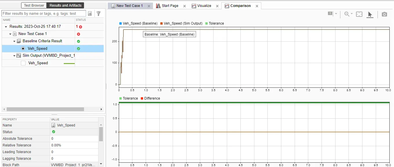
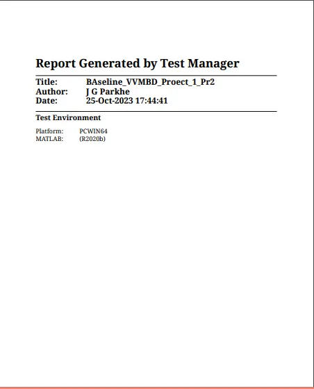
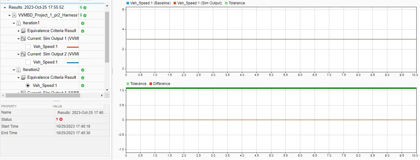
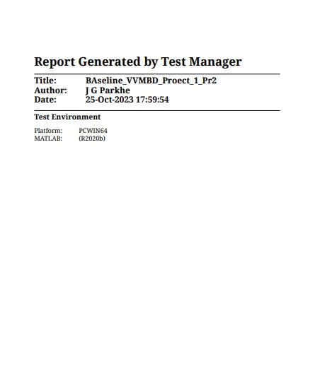
Step 11: Baseline Test
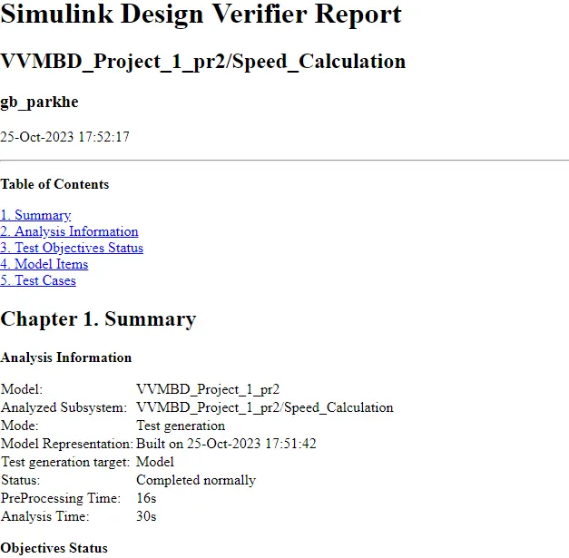
Step 12: Back to Back Test:
OUTPUT:
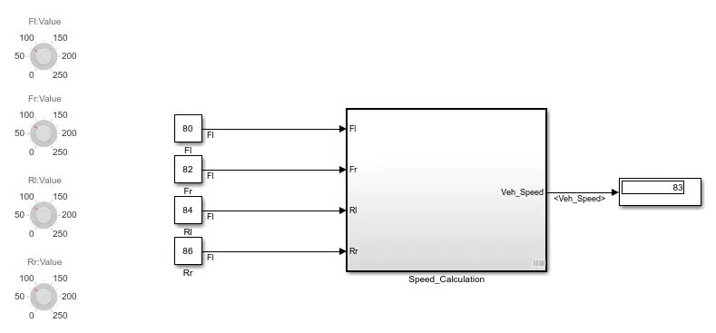
1) All sensors are working,
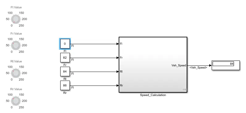
2) One Sensor is Down,
3) Any two sensors are down,
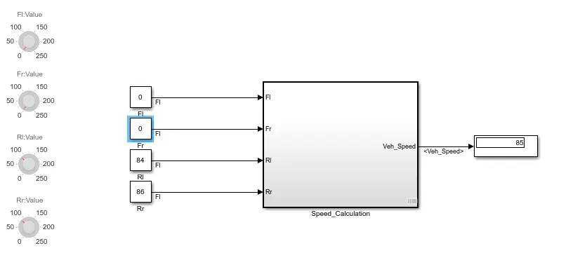
4) Three Sensors are down,
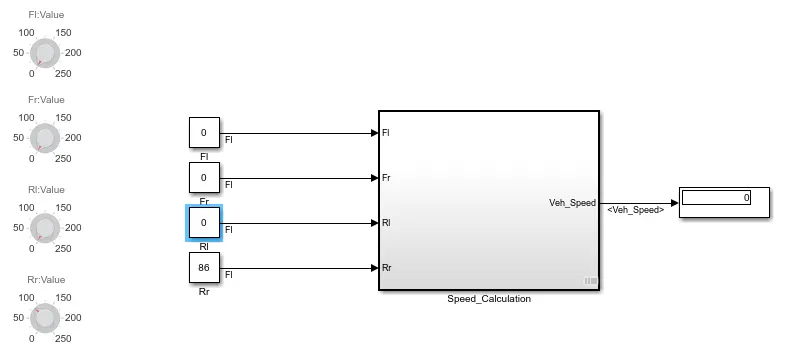
Conclusion:
The Simulink model created for ABS vehicle speed calculation is working as per expectations.
The rigorous assessment of model is carried out using different tools in MATLAB such as
· Requirement tagging
· Model advisor - JMAAB compliance
· Fixed-point Tool
· SLDV Design error detection report
· Functional test case, MIL, SIL harness
· SLDV test generation
· Auto-code generation, main , .c & .h files
· Poly space analysis
· Test manager – baseline & back-to-back testing
The reports for each task is generated and attached herewith(VVMBD_Prj1_pr2.zip).