Project 1 (Mini Project on Vehicle Direction Detection
Mini Project - Vehicle Direction Determination
Aim: Identification of direction of the vehical based on camera input.
Objective of Mini Project:
- Development of MATLAB Simulink model as per requirement.
- Tag the requirements to the simulink model; tagging requirement 1 & requirement 2 to their corresponding subsystems is fine.
- MBD compliant changes, Data Dictionary creation & code generation is added advantage, and that is not scope of this project.
- If choosing code generation, Storage class for Input signals: ImportedExtern; Storage class for Output signal: Export to File; Storage class for local signals: localizable; Storage class for calibration signals: Const.
- Choose sample time for all signals as 0.01s
Explanation:
1. Creating Simulink data dictionary file (.sldd)
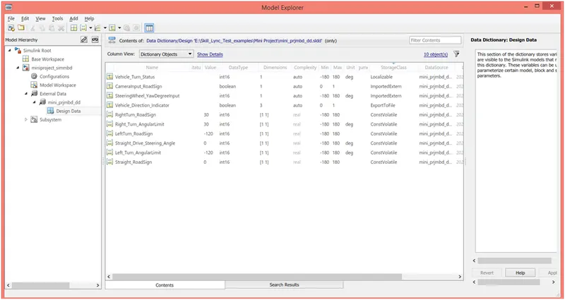
2. Creation of main subsystem:
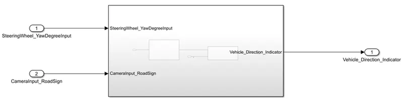
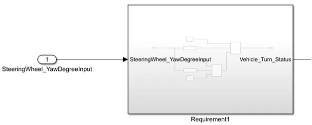
3. Developing logic in Simulink as per the requirement stated in Requirement 1.

4.Creating subsystem in the main subsystem for Requirement 1.
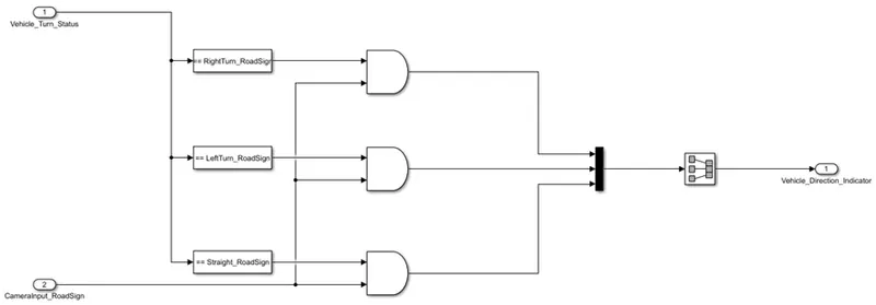
5. Similarly developing logic in Simulink as per the requirement stated in Requirement 2 and creating its subsystem.
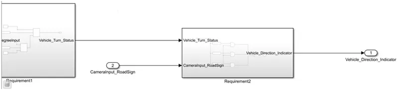
6. Tagging requirement 1 & requirement 2 to their corresponding subsystems.
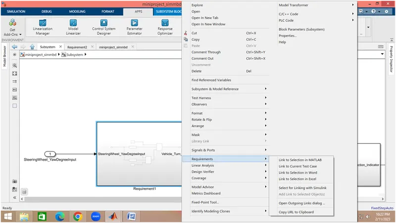
6.a. The word document is created in which details of requirements are given. Perticular text containing requirement details is selected.
6.b. To accomlish tagging following procedure is adpated,
Right click on Subsystem → go to requirement → click on selection in word
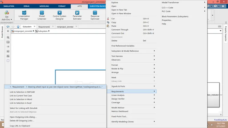
6.c. To see requirement document is tagged or not, follow the same procedure in 6.b.
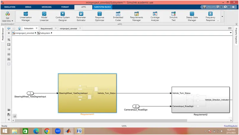
7. Resolving Signals in the model.
7.a. Whereever signals are getting generated for the first time in the simulink model they are resolve. Following is the procedure,
Right click on signal → go to Properties → Type signal name → check the box 'Signal name must resolve to Simulink signal object' → Apply → Ok
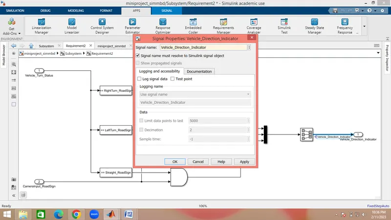
7.b. Signal are propogated by performing following procedure,
Right click on signal → go to Properties → check the box 'Show propgated signal' → Apply → Ok
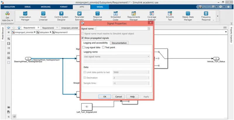
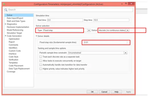
8. Simulink Configuration parameters settings, Click on Model Properties and following settings are done.
8.a In solver, type of solver is selected as Fixed-step, Solver is selected as Discrete, Fixed-step size is entered as 0.01
8.b In Code generation, Click on browse → select ert.tlc Embedded coder → click on Apply → Ok.
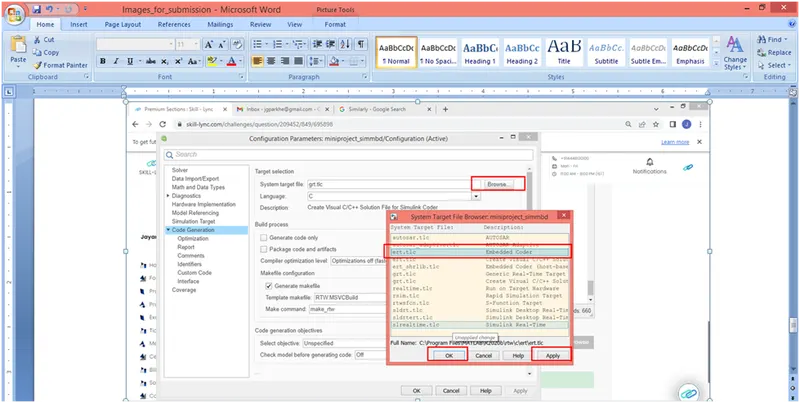
Then click on Apply and Ok.
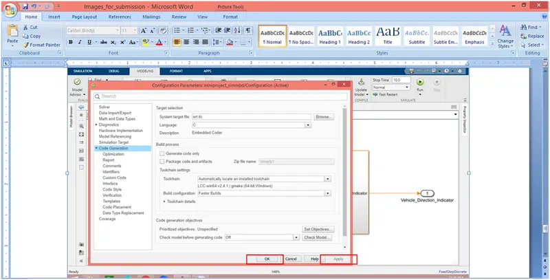
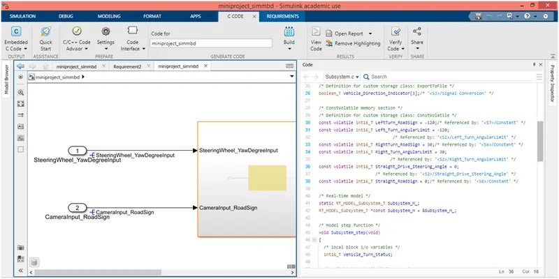
9. Code Generation:
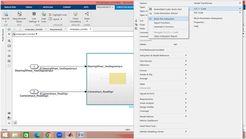
9.a. Right click on main Subsystem → go to c/c++ code → click on Built this system
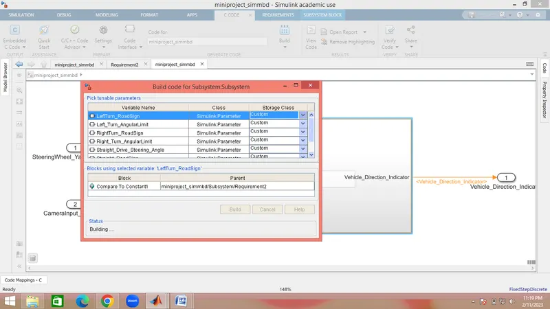
9.b. Click on Build.
9.c. Dignostic will get open. If error is there it will be located in digostic.
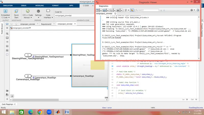
9.d. The Code generated is as follows,
Result: Hence the simulink model is developed as per the reqirements given and embedded code is also generated for vehical direction detection.