Project 2 Adaptive Cruise Control
NAME: MADHU D
BATCH: 07
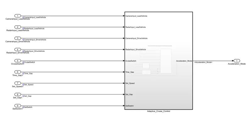
AIM: To develop the model of Adaptive Cruise Control feature as per the given requirement using MATLAB Simulink.
MODEL:
Requirement 1– Lead Vehicle:
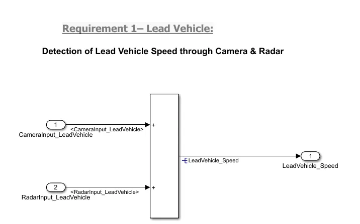
- Lead Vehicle is a vehicle which is driving in the road ahead of our drive vehicle. Two input signals (Signal Name: CameraInput_LeadVehicle & RadarInput_LeadVehicle).
- Ideally sensor fusion techniques will be deployed to process & analyze data from camera & radar. For complexity reasons, let’s not adapt to any such algorithms.
- We can simply add both the radar & camera inputs & the corresponding output is read as Speed profile output (Signal Name: LeadVehicle_Speed).
- Speed data of the lead vehicle is critical in implementing the Adaptive Cruise Control algorithm.
Requirement 2 – Drive Vehicle:
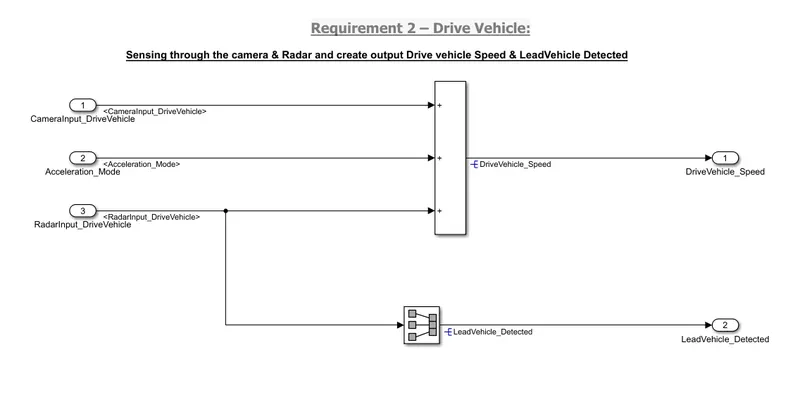
- Drive Vehicle is the vehicle driven by the user & this is the vehicle which has ACC algorithm in it.
- Like the Lead Vehicle, Drive Vehicle algorithm also has 2 input signals (Signal Name: CameraInput_DriveVehicle, RadarInput_DriveVehicle) & one signal coming as an Input to this subsystem (Signal Name: Acceleration_Mode) – three inputs into this requirement in total.
- Like the above requirement, sensor fusion techniques will also be deployed here, for complexity reasons we are ignoring them.
- Two output signals come from this subsystem (Signal Name: DriveVehicle_Speed & LeadVehicle_Detected).
- Signal DriveVehicle_Speed is summation of three input signals mentioned above & LeadVehicle_Detected is renamed from Input Signal RadarInput_DriveVehicle by mere use of Signal Conversion block.
Requirement 3 – Adaptive Cruise Control Algorithm:
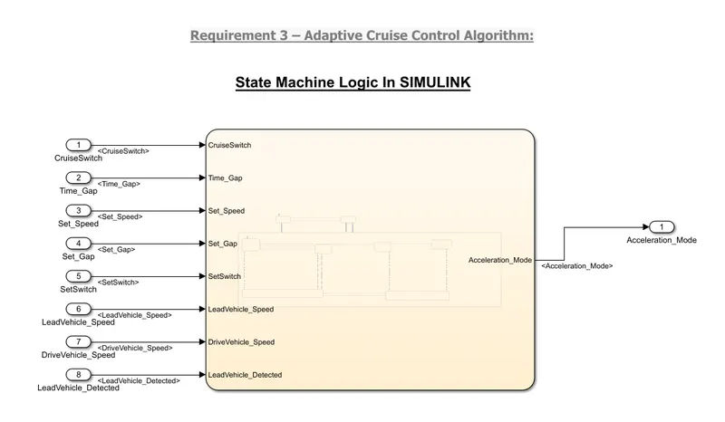
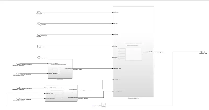
- Adaptive Cruise Control feature has 3 major modes of operation: OFF Mode, STANDBY Mode & ON Mode. This particular requirement has to be implemented as state machine logic in Simulink.
- The input signals to this state machine system are (Signal Name: Time_Gap, Set_Speed, Set_Gap, CruiseSwitch, SetSwitch).
- Also, the output signals (Signal Name: DriveVehicle_Speed & LeadVehicle_Detected) from requirement-2 is fed back as an input signal into this state machine block.
- Additionally, output signal (Signal Name: LeadVehicle_Speed) from requirement-1 is given as an input signal to this state machine block as well.
- Output from this subsystem is a signal (Signal Name: Acceleration_Mode) which governs the vehicular speed of the drive vehicle which automatically adjusts its speed & velocity to match the lead vehicle.
Requirement are tagged in a word file which is uploaded: right click on subsystem -> Requirement-> requirement tag
SLDD(Simulink Data Dictionary)
To make model's data accessible, here the data has been made available for model by using SLDD
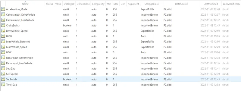
A simulink data dictionary file is uploaded.
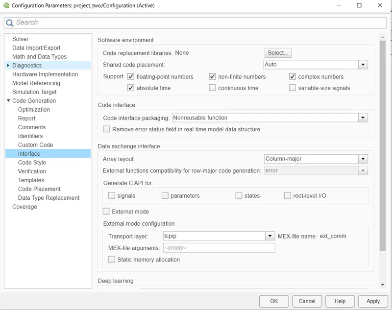
Settings made at Configuration Parameters
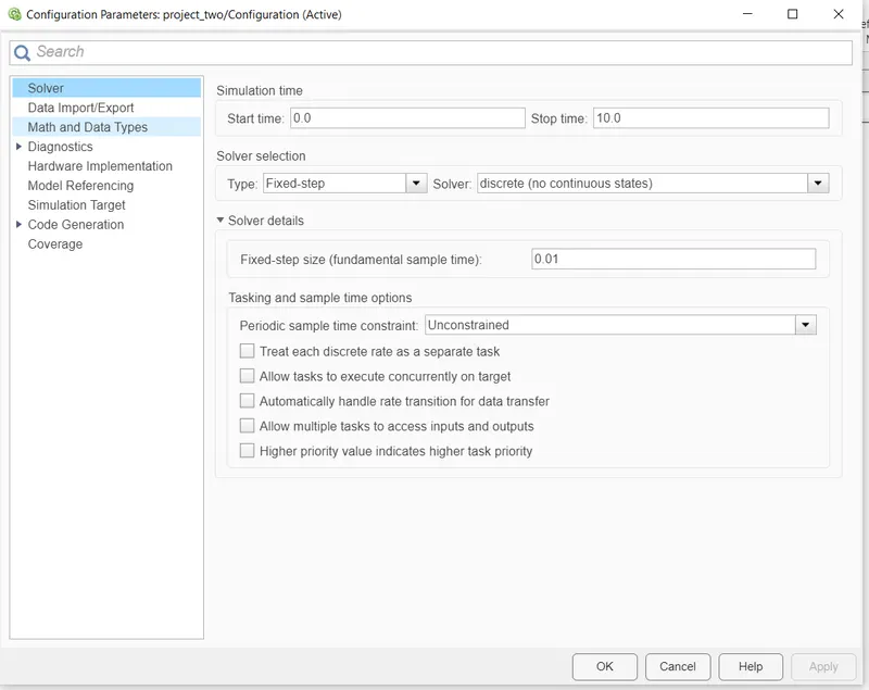
under Code Generation settings
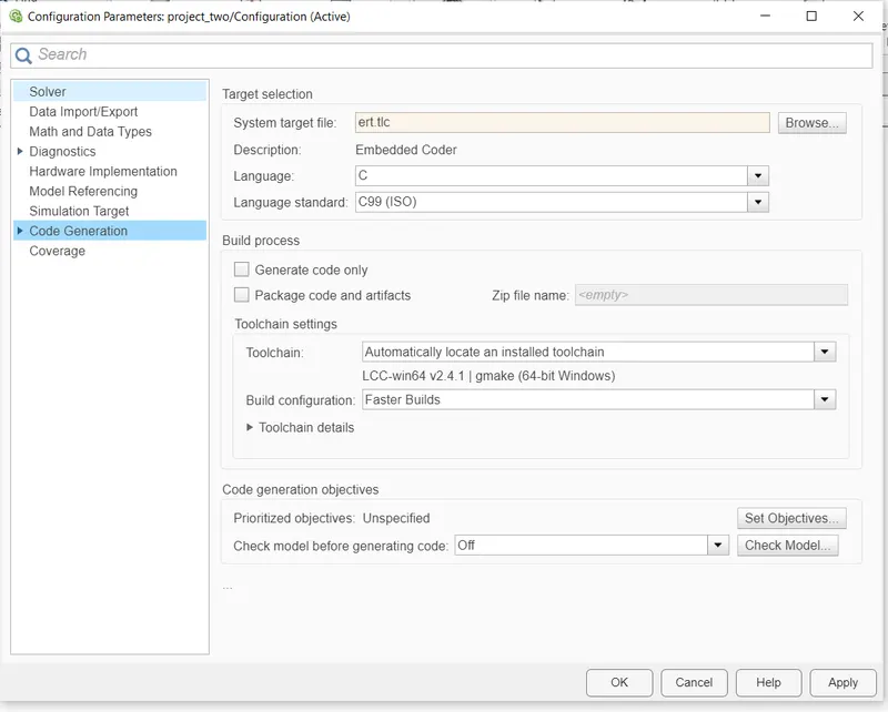
Running Model Advisor checks
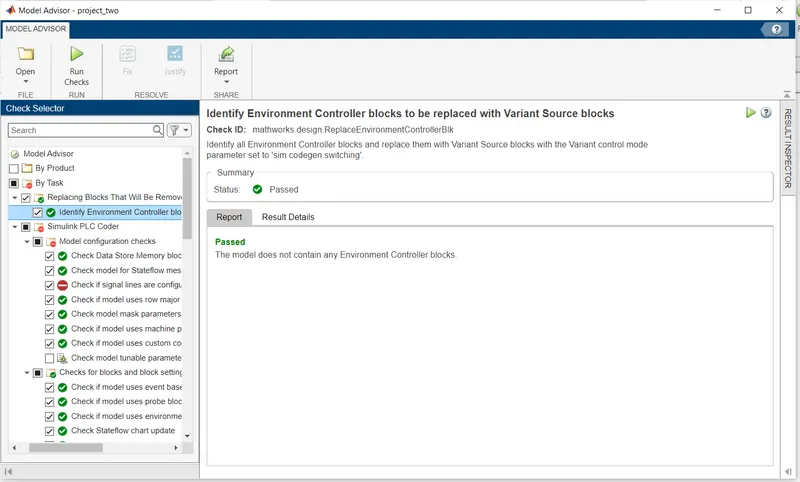
A report file is uploaded.
Code Generation
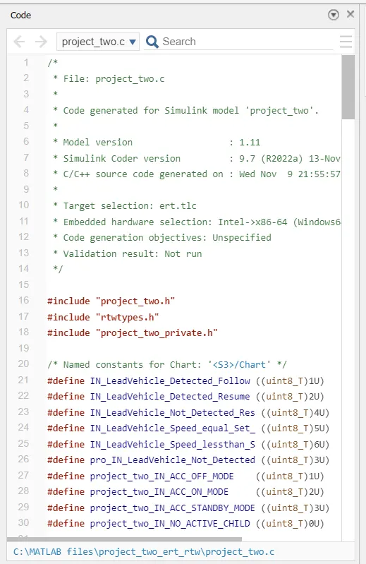
This code files are uploaded
RESULT:
Adaptive cruise control is designed according to the given requirements and the code is generated by using embedded coder. The model is checked using Model Advisor and report is uploaded. There are many advance features in the Adaptive cruise control like the vehicle automatically changes the speed according to the road condition, traffic, turning and slope.
The weather condition may affect the sensor output which may lead to serious damage to vehicle and driver. So it has some limitations, it is not advisable to use ACC in the Bad weather conditions such as heavy rain, storm, snow and foggy.