Project 2 Adaptive Cruise Control
LIVE BATCH -07
Aim: To create a Simulink model for a passenger vehicle which will work as a Adapative Cruise Control feature.
Objective of the project:
- Developing Adaptive Cruise Control feature as per the Requirement Document using MATLAB Simulink.
- Follow all the MBD related processes: Requirement Tagging & Traceability, SLDD creation, Configuration Parameter changes, Model Advisor check & Code Generation.
- In Configuration Parameters: enable “Support Floating Numbers” under Code Generation settings.
- Use Embedded Coder to generate the code.
- If choosing code generation, Storage class for Input signals: ImportedExtern; Storage class for Output signal: Export to File; Storage class for local signals: localizable; Storage class for calibration signals: Const.
- Choose sample time for all signals as 0.01s
Description:
Adaptive Cruise Control (ACC) extends existing cruise control systems to include a headway sensor that monitors the distance between your vehicle and the vehicle ahead. The system is also sometimes called Active Cruise Control (ACC) or Intelligent Cruise Control (ICC). ACC systems are similar to the conventional cruise control systems in the way they maintain the vehicle preset speed. However, unlike conventional systems, ACC automatically adjusts the speed of the vehicle in order to maintain a safe distance from vehicles ahead in the same lane. The system automatically monitors road traffic patterns, employing a headway sensor capable of detecting vehicles at distances up to 500 ft, and using the throttle and brakes to maintain a pre-set distance behind the vehicle ahead. When the road is clear again, the system re-accelerates to the pre-set velocity.
There are two key types of headway sensors. Radar sensors employ microwave signals (typically at 35 or 76 GHz). Lidar sensors employ a laser diode to produce infrared light signals. Both types of sensors send a signal and monitor the time required for the signal to reflect off the object ahead. Optical or infrared image sensors are also being introduced for the purpose of detecting vehicles on the road ahead. These sensors can replace or supplement the information from radar or lidar sensors.
When ACC systems determine there is a need to slow the vehicle, they may use the engine, transmission and/or brakes to decrease the vehicle's speed and maintain a safe following distance. Many systems limit the maximum deceleration to no more than 3 m/s2 (10 ft/s2), although systems are beginning to appear that allow more aggressive braking (see Automic Brakin). The ACC user interface typically has both visual and audible indications that are provided to the driver depending on the severity of the situation. ACC systems can always be disengaged through the use of the brake pedal or the primary ACC user interface. In addition, certain stability systems such as traction control, and electronic stability control may also turn the ACC system off. ACC systems are evolving rapidly and are currently available on many mid- to high-end passenger cars as well as many heavy duty commercial trucks.
Adaptive Cruise Control Feature for passenger cars allows the host vehicle to adapt to the speed in line with the flow of traffic. Driving in heavy traffic or keeping a safe distance to the preceding vehicle calls for a high level of concentration. The Adaptive Cruise Control feature can reduce the stress on the driver by automatically controlling the vehicle speed & maintaining a predefined minimum distance to the preceding vehicle. As a consequence, the driver enjoys more comfort & can concentrate on the road little better.
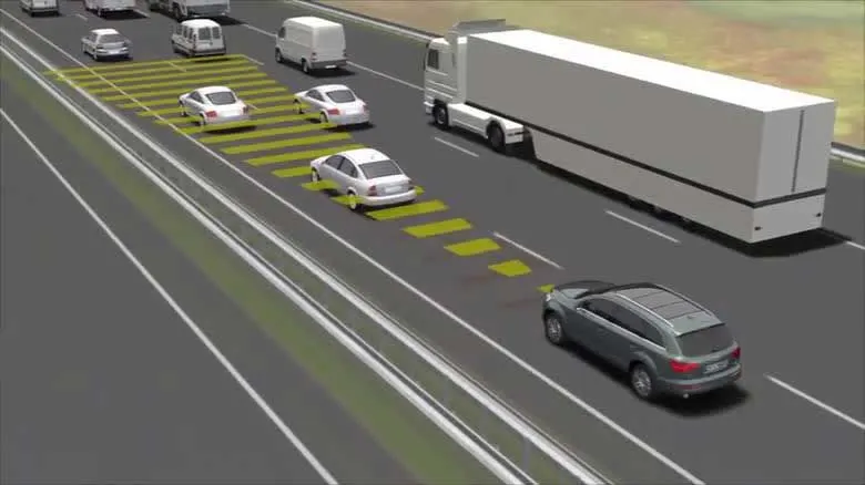
A radar sensor is usually at the core of the Adaptive Cruise Control. Installed at the front of the vehicle, the system permanently monitors the road ahead. As long as the road ahead is clear, cruise control feature maintains the speed set by the driver. If the system spots a slower vehicle within its detection range, it gently reduces speed by releasing the accelerator or actively engaging the brake control system. If the vehicle ahead speeds up or changes lanes, the cruise control automatically accelerates to the driver’s desired speed.
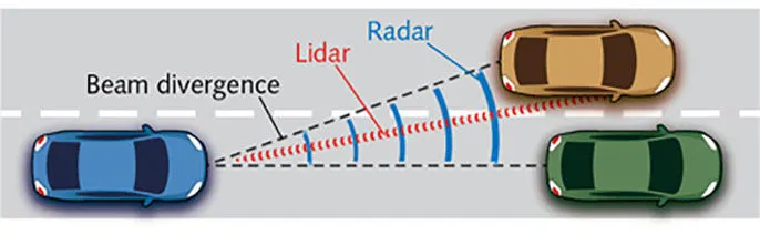
How Radar and Lidar Sensors Work
Standard Adaptive Cruise Control can be activated from speeds of around 30 km/h (20 mph) upwards and supports the driver, primarily on cross-country journeys or on freeways. The cruise control stop & go variant is also active at speeds below 30 km/h (20 mph). It can maintain the set distance to the preceding vehicle even at very low speeds and can decelerate to a complete standstill. When the vehicle remains stopped longer, the driver needs only to reactivate the system, for example by briefly stepping on the gas pedal to return to cruise control mode. In this way, cruise control stop & go supports the driver even in heavy traffic and traffic jams.
Since Adaptive Cruise Control is a comfort and convenience system, brake interventions and vehicle acceleration only take place within defined limits. Even with Adaptive Cruise Control switched on, it remains the driver’s responsibility to monitor the speed and distance from the vehicle in front.
Simulink Model As per the requiremnets mentioned:
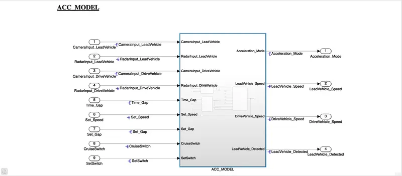
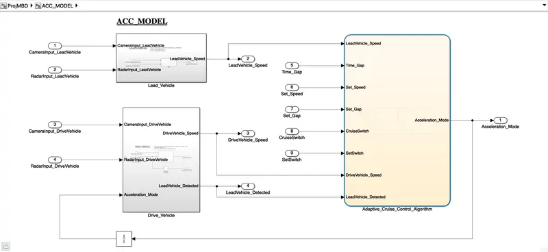
The above is teh final model that has been created by fulfilling all the requirements of the project and the model below is the Subsystems from which this model is been created:
Enabled Subsystem Model:
Procedure :
The below are the requiremnets taht we have to keep in mind while creating the model and we have. So the we will start with the first requirement of the project and that is
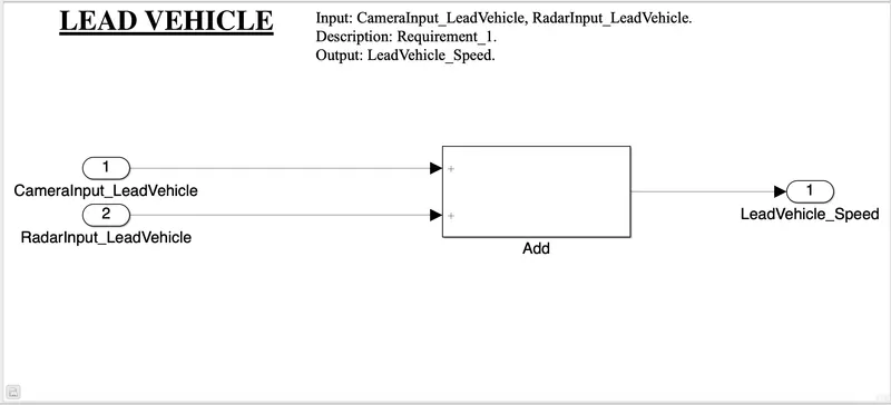
Requirement 1– Lead Vehicle:
- Lead Vehicle is a vehicle which is driving in the road ahead of our drive vehicle. Two input signals (Signal Name: CameraInput_LeadVehicle & RadarInput_LeadVehicle).
- Ideally sensor fusion techniques will be deployed to process & analyze data from camera & radar. For complexity reasons, let’s not adapt to any such algorithms.
- We can simply add both the radar & camera inputs & the corresponding output is read as Speed profile output (Signal Name: LeadVehicle_Speed).
- Speed data of the lead vehicle is critical in implementing the Adaptive Cruise Control algorithm.
The subsystem is basically on the Lead vehicle which will be ahead of the drive vehicle so we just need to give the inputs as Camera Input and the Radar Input. The output that we will be getting from this will be the Lead Vehicle's Speed
The Subsystem created with the help of teh first requirement is as follows:
Requirement 2 – Drive Vehicle:
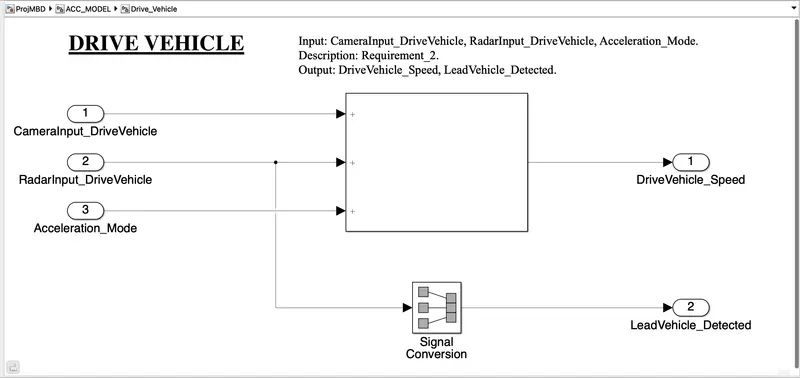
- Drive Vehicle is the vehicle driven by the user & this is the vehicle which has ACC algorithm in it.
- Like the Lead Vehicle, Drive Vehicle algorithm also has 2 input signals (Signal Name: CameraInput_DriveVehicle, RadarInput_DriveVehicle) & one signal coming as an Input to this subsystem (Signal Name: Acceleration_Mode) – three inputs into this requirement in total.
- Like the above requirement, sensor fusion techniques will also be deployed here, for complexity reasons we are ignoring them.
- Two output signals come from this subsystem (Signal Name: DriveVehicle_Speed & LeadVehicle_Detected).
- Signal DriveVehicle_Speed is summation of three input signals mentioned above & LeadVehicle_Detected is renamed from Input Signal RadarInput_DriveVehicle by mere use of Signal Conversion block.
In this requirement a subsystem is created which is the Drive Vehicle. So the Drive vehicle is basically our User's vehicle and the input to this vehicle will be the Camera Input, Radar Input and Acceleration mode. The output we are getting from this model are the Drive Vehicle Speed and the Lead Vehcile Detected ahead of the this Drive Vehicle.
The subsystem created out of this requirement is as follows:
Requirement 3 – Adaptive Cruise Control Algorithm:
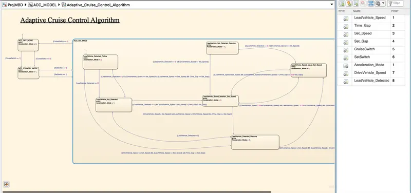
- Adaptive Cruise Control feature has 3 major modes of operation: OFF Mode, STANDBY Mode & ON Mode. This particular requirement has to be implemented as state machine logic in Simulink.
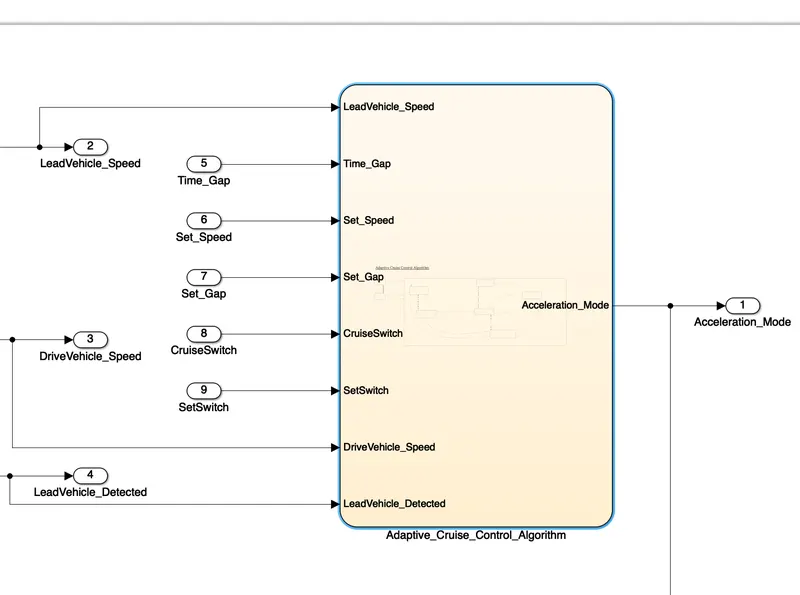
- The input signals to this state machine system are (Signal Name: Time_Gap, Set_Speed, Set_Gap, CruiseSwitch, SetSwitch).
- Also, the output signals (Signal Name: DriveVehicle_Speed & LeadVehicle_Detected) from requirement-2 is fed back as an input signal into this state machine block.
- Additionally, output signal (Signal Name: LeadVehicle_Speed) from requirement-1 is given as an input signal to this state machine block as well.
- Output from this subsystem is a signal (Signal Name: Acceleration_Mode) which governs the vehicular speed of the drive vehicle which automatically adjusts its speed & velocity to match the lead vehicle.
To fulfill the third requirement, an Algorithm is created which include the stateflow. So the Algorithm contains three modes and the inputs for this stateflow will be Time Gap, Set Speed, Set Gap, Cruise Switch, Set Switch, Drive Vehicle Speed, Lead Vehicle Speed, Lead Vehicle Speed. The Output for this is Acceleration Mode which is given as a feedback to the Second requirement.
Requirement 3a – ACC OFF MODE state logic:
- This is the default state inside state machine logic. Output signal Acceleration_Mode is at value 0 in this state.
- This state is governed by input signal CruiseSwitch.
- If CruiseSwitch is equal to 1, state ACC STANDBY mode will get activated. If CruiseSwitch is equal to 0, state ACC OFF mode will get activated, from either ACC ON mode or ACC STANDBY mode
Requirement 3b – ACC STANDBY MODE state logic:
- This is the second activated state inside state machine logic. Output signal Acceleration_Mode is at value 1 in this state.
- This state is governed by both input signals CruiseSwitch & SetSwitch.
- If CruiseSwitch is equal to 1, state ACC STANDBY mode will get activated. If CruiseSwitch is equal to 0, state ACC OFF mode will get activated, from either ACC ON mode or ACC STANDBY mode
- If SetSwitch is equal to 1, state ACC ON mode will get activated. If SetSwitch is equal to 0, state ACC STANDBY mode will get activated.
Requirement 3c – ACC ON MODE state logic:
This state will be activated when input signal SetSwitch is equal to 1. There are 6 sub states to this state logic: They are:
- LeadVehicle_Detected_Follow (Default)
- LeadVehicle_Not_Detected
- LeadVehicle_Detected_Resume
- LeadVehicle_Not_Detected_Resume
- LeadVehicle_Speed_lessthan_Set_Speed
- LeadVehicle_Speed_equal_Set_Speed
Requirement 3c (i) – LeadVehicle_Detected_Follow (ACC ON MODE):
- This is the default sub state inside ACC ON MODE state. Output signal Acceleration_Mode is equal to 2.
- Condition to transit from LeadVehicle_Detected_Follow to LeadVehicle_Not_Detected; Input signal condition LeadVehicle_Detected == 0.
- Condition to transit from LeadVehicle_Detected_Follow to LeadVehicle_Speed_lessthan_Set_Speed; Input Signals condition (LeadVehicle_Detected == 1) && (LeadVehicle_Speed < Set_Speed) || (Time_Gap < Set_Gap).
Requirement 3c (ii) – LeadVehicle_Not_Detected (ACC ON MODE):
- Output signal Acceleration_Mode is equal to 1.
- Condition to transit from LeadVehicle_Not_Detected to LeadVehicle_Detected_Follow; Input signals condition [(LeadVehicle_Detected==1) && (DriveVehicle_Speed == Set_Speed) && (LeadVehicle_Speed >= Set_Speed) && (Time_Gap >= Set_Gap)]
- Condition to transit from LeadVehicle_Not_Detected to LeadVehicle_Speed_lessthan_Set_Speed; Input signals condition [(LeadVehicle_Detected == 1) && (LeadVehicle_Speed < Set_Speed) || (Time_Gap < Set_Gap)]
Requirement 3c (iii) – LeadVehicle_Detected_Resume (ACC ON MODE):
- Output signal Acceleration_Mode is equal to 3.
- Condition to transit from LeadVehicle_Detected_Resume to LeadVehicle_Detected_Follow; Input signals condition [(DriveVehicle_Speed == Set_Speed) && (LeadVehicle_Speed >= Set_Speed) && (Time_Gap >= Set_Gap)]
- Condition to transit from LeadVehicle_Detected_Resume to LeadVehicle_Not_Detected_Resume; Input signal condition LeadVehicle_Detected==0.
- Condition to transit from LeadVehicle_Detected_Resume to LeadVehicle_Speed_equal_Set_Speed; Input Signal condition [(DriveVehicle_Speed < Set_Speed) && (LeadVehicle_Speed > DriveVehicle_Speed) && (Time_Gap >= Set_Gap)]
Requirement 3c (iv) - LeadVehicle_Not_Detected_Resume (ACC ON MODE):
- Output signal Acceleration_Mode is equal to 1.
Requirement 3c (v) - LeadVehicle_Speed_lessthan_Set_Speed (ACC ON MODE):
- Output signal Acceleration_Mode is equal to 4.
- Condition to transit from LeadVehicle_Speed_lessthan_Set_Speed to LeadVehicle_Not_Detected; Input signal condition [(LeadVehicle_Detected == 0) && (DriveVehicle_Speed == Set_Speed)]
- Condition to transit from LeadVehicle_Speed_lessthan_Set_Speed to LeadVehicle_Speed_equal_Set_Speed; Input signals condition [((LeadVehicle_Speed*1.25>=DriveVehicle_Speed) && (LeadVehicle_Speed * 0.75<=DriveVehicle_Speed)) && (DriveVehicle_Speed < Set_Speed) && ((Time_Gap<=1.25*Set_Gap) && (Time_Gap >=0.75*Set_Gap))]
Requirement 3c (vi) - LeadVehicle_Speed_equal_Set_Speed (ACC ON MODE):
- Output signal Acceleration_Mode is equal to 5.
- Condition to transit from LeadVehicle_Speed_equal_Set_Speed to LeadVehicle_Not_Detected_Resume; Input signal conditions is [(LeadVehicle_Detected == 0) || (DriveVehicle_Speed <= Set_Speed)]
- Condition to transit from LeadVehicle_Speed_equal_Set_Speed to LeadVehicle_Detected_Resume; Input signal conditions [(DriveVehicle_Speed < Set_Speed) && (LeadVehicle_Speed > DriveVehicle_Speed) || (Time_Gap >= Set_Gap)]
- Condition to transit from LeadVehicle_Speed_equal_Set_Speed to LeadVehicle_Speed_lessthan_Set_Speed; Input signals conditions [(LeadVehicle_Speed<Set_Speed) && (LeadVehicle_Speed<DriveVehicle_Speed) || (Time_Gap == 0.75*Set_Gap)]
All the above requirements are fulfilled in the below model :
CONFIGURATION PARAMETER SETTINGS:
We have to set the Solver settingand Code generation settings. Under Solver setting, the solver type must be Fixed Step type and the Solver must be Discrete (no continuous state).
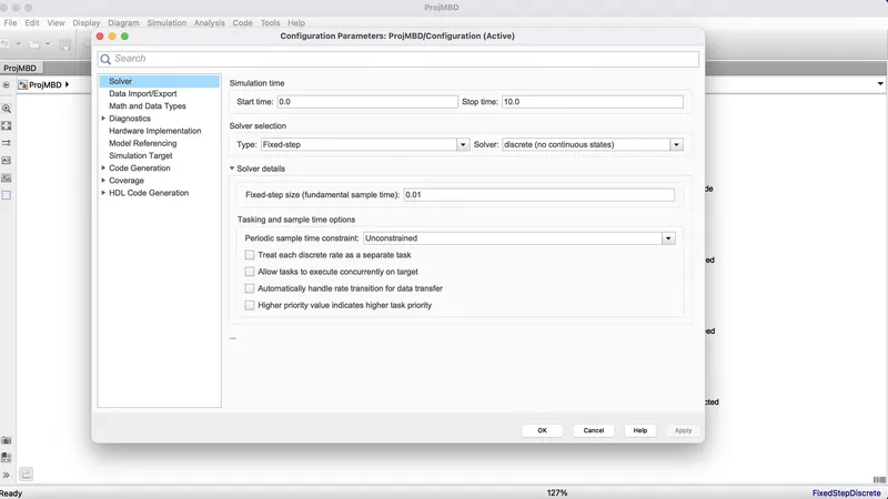
And under the Code generation setting the Embedded coder must e selected and the sample time for all the signals must be set to 0.01.
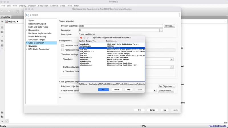
The model is being created now we need to add the signals and constants in the Simulink Data Dictionary.
Linking of Simulink Data Dictionary:
Signals and constants are provided by the Project question in order to create a Simulink Data Dictionary for this model.
Signals & Calibration Data List:
|
Signal / Calibration Name |
Signal Type |
Data Type |
Dimension |
Min |
Max |
Initial Value |
Units |
|
CameraInput_LeadVehicle |
Input |
Uint8 |
1 |
0 |
255 |
- |
- |
|
RadarInput_LeadVehicle |
Input |
Uint8 |
1 |
0 |
255 |
- |
- |
|
CameraInput_DriveVehicle |
Input |
Uint8 |
1 |
0 |
255 |
- |
- |
|
RadarInput_DriveVehicle |
Input |
Uint8 |
1 |
0 |
255 |
- |
- |
|
Time_Gap |
Input |
Uint8 |
1 |
0 |
255 |
- |
- |
|
Set_Speed |
Input |
Uint8 |
1 |
0 |
255 |
- |
- |
|
Set_Gap |
Input |
Uint8 |
1 |
0 |
255 |
- |
- |
|
CruiseSwitch |
Input |
Boolean |
1 |
0 |
1 |
- |
- |
|
SetSwitch |
Input |
Boolean |
1 |
0 |
1 |
- |
- |
|
Acceleration_Mode |
Output |
Uint8 |
1 |
0 |
255 |
- |
- |
|
LeadVehicle_Speed |
Output |
Uint8 |
1 |
0 |
255 |
- |
- |
|
DriveVehicle_Speed |
Output |
Uint8 |
1 |
0 |
255 |
- |
- |
|
LeadVehicle_Detected |
Output |
Uint8 |
1 |
0 |
255 |
- |
- |
The following are steps in order to add the information to the SLDD
Firstly we need to click on the gear like option at the top of the window which says Model Explorer : By clicking on the model properties, a window will pop-up saying model properties. It will contain five parameters 1) Main 2) Callbacks 3) History 4) Description 5) Data.Under the Data we have need to select the Data Dictionary under taht New. Once on clicking New there pops-up a window for creating the New Data Duictionary. We need to save the file wherever we want. Once it is done, the simulink model will appear, in that at the Left Bottom of the screen, click on that , then it will take you to the Model Hierarchy.
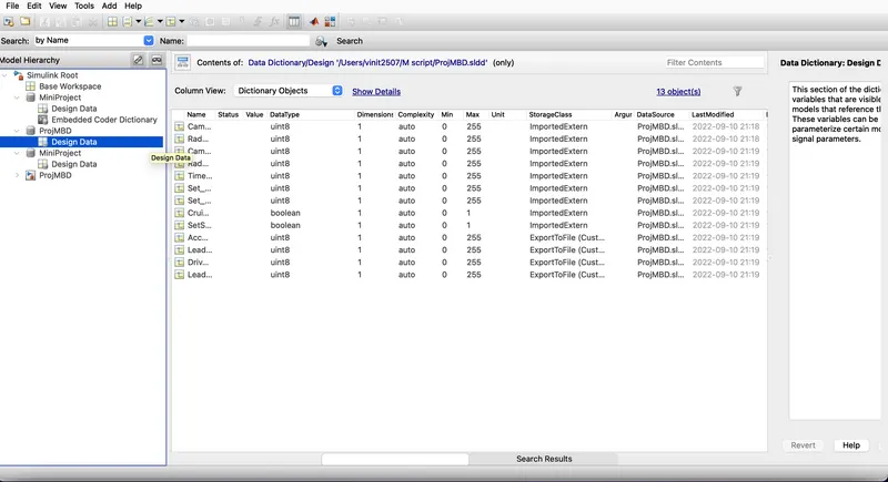
Signal resolving and Signal Propogation:
All the signals in the model must be resolved in order to get the appropriate output from the model. The steps for resolvinng the signasl are as follows:
Right click on the signal that has to be resolved -->Properties.
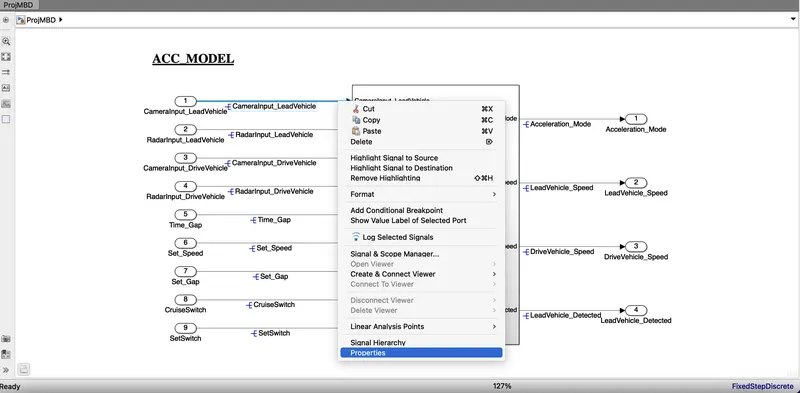
In properties --> Write the name of the signal and under that we need to check the option that says Signal name must resolve o Simulink signal object.
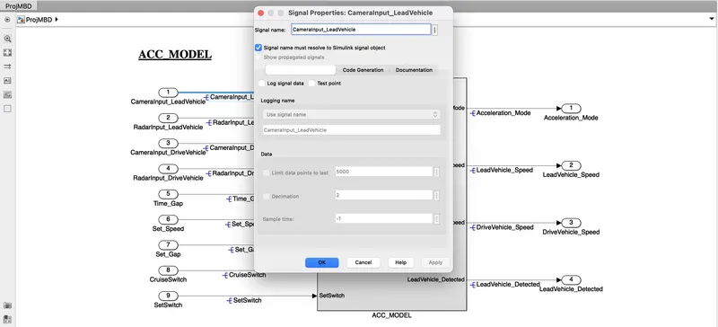
Once it is done then teh name of the signal appears on the signal along with the -E sign on it .
Requirement Tagging and Tracebility report :
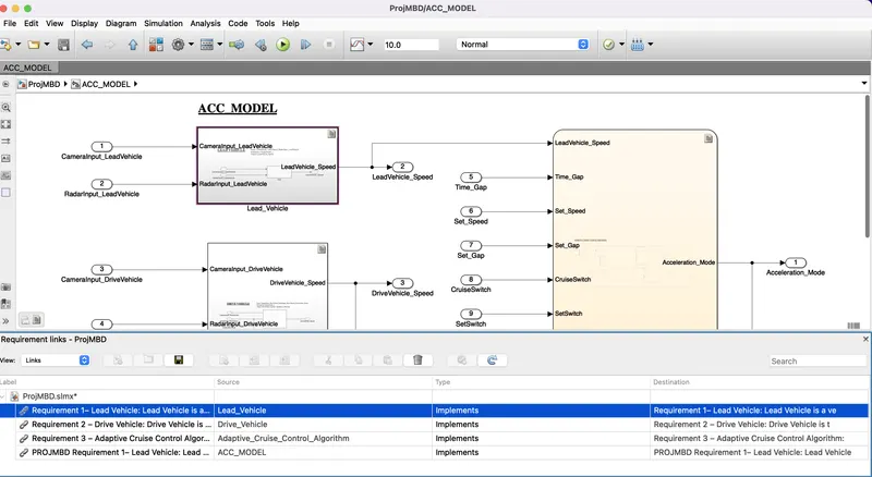
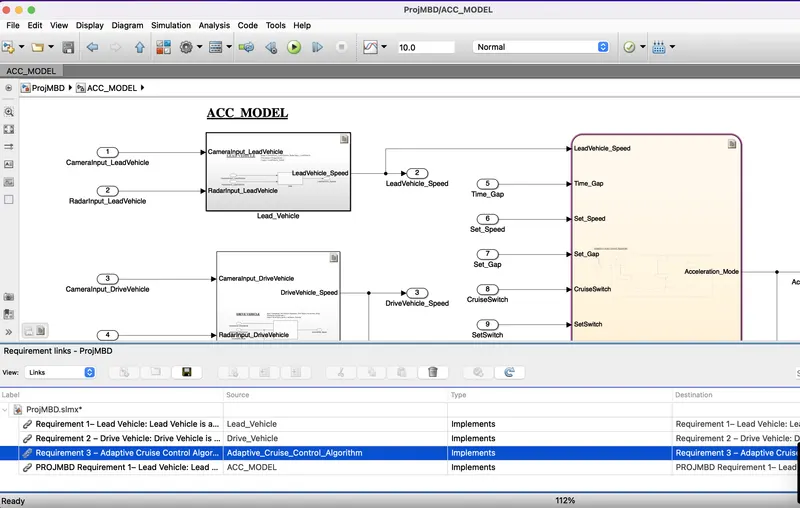
all the requirements are tagged for better understandability, anyone who is reviewing the model or who is trying to update the model can get a clear idea of what logic is used in the system. from the requirement manager, we can see what are all are tagged and the description.
Model Advisor Report Generation:
Now we will generate teh Model Advisor Report of this model in order to check if there are any Failed conditiosn or any errors are present in the model. It helps us to improve the efficiency of the model as from this report we can get the errors, and warnings that the model is having just by doing the Model Advidory Check. Later on we can fix teh errors that are present in the model.
The steps for generating the Model Advisor Report are as follows:
Firstly we need to click on the Analysis option that is present at the top of the Simulink model then under that Model Advidor will be present.
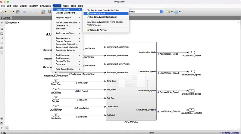
On clicking that it will take you to the Model Advisor window. In that we need to select the By Task option and under that we need to run the checks for only the Modeling Standards for MAAB.
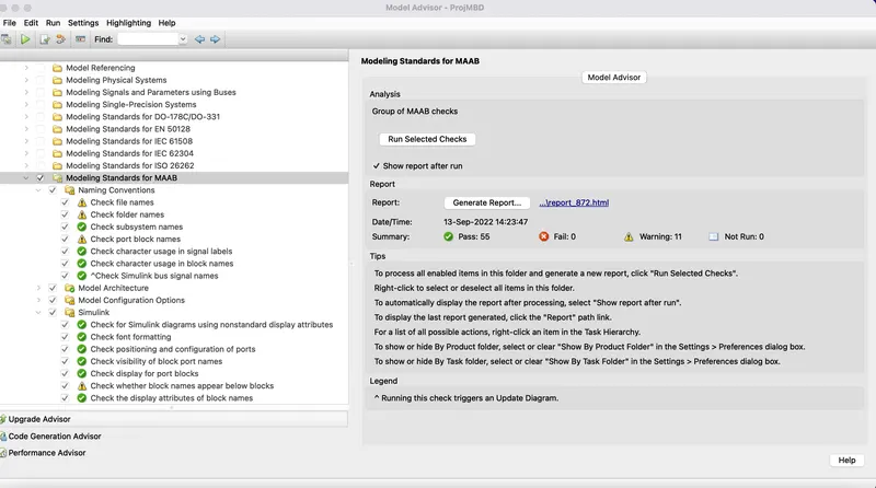
We can also generate the report from the Model advisor test.
So here we can see that there is no failed condition and the number of warnings is 13. Now we can go further and generate the Code for this model
Code Generation:
For generating the code we need to follow few steps and they are
Click on Code in the simulink mode window on the top, on clciking various options will appear, select c/c++ from the option, on doing that click on Build Model.
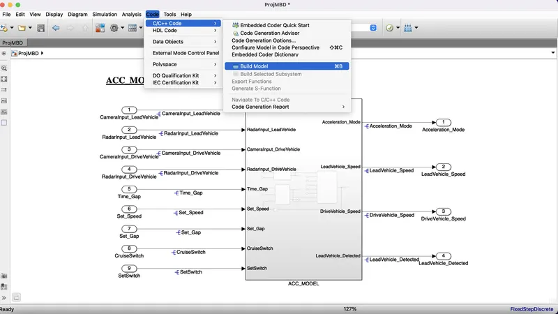
A window will pop up with lots of things that will have Summary, Subsystem Report, Code interface Report ,ert_main.c, .c files ete. Click on the .c file and teh code will appear.
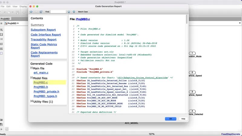
File: ProjMBD.c

1	/*
2	 * File: ProjMBD.c
3	 *
4	 * Code generated for Simulink model 'ProjMBD'.
5	 *
6	 * Model version                  : 1.26
7	 * Simulink Coder version         : 8.14 (R2018a) 06-Feb-2018
8	 * C/C++ source code generated on : Fri Sep 16 00:15:15 2022
9	 *
10	 * Target selection: ert.tlc
11	 * Embedded hardware selection: Intel->x86-64 (Windows64)
12	 * Code generation objectives: Unspecified
13	 * Validation result: Not run
14	 */
15
16	#include "ProjMBD.h"
17	#include "ProjMBD_private.h"
18
19	/* Named constants for Chart: '<S1>/Adaptive_Cruise_Control_Algorithm' */
20	#define IN_LeadVehicle_Detected_Follow ((uint8_T)1U)
21	#define IN_LeadVehicle_Detected_Resume ((uint8_T)2U)
22	#define IN_LeadVehicle_Not_Detected_Res ((uint8_T)4U)
23	#define IN_LeadVehicle_Speed_equal_Set_ ((uint8_T)5U)
24	#define IN_LeadVehicle_Speed_lessthan_S ((uint8_T)6U)
25	#define Pro_IN_LeadVehicle_Not_Detected ((uint8_T)3U)
26	#define ProjMBD_IN_ACC_OFF_MODE        ((uint8_T)1U)
27	#define ProjMBD_IN_ACC_ON_MODE         ((uint8_T)2U)
28	#define ProjMBD_IN_ACC_STANDBY_MODE    ((uint8_T)3U)
29	#define ProjMBD_IN_NO_ACTIVE_CHILD     ((uint8_T)0U)
30
31	/* Exported data definition */
32
33	/* Definition for custom storage class: ExportToFile */
34	uint8_T Acceleration_Mode;
35	uint8_T DriveVehicle_Speed;
36	uint8_T LeadVehicle_Detected;
37	uint8_T LeadVehicle_Speed;
38
39	/* Block states (default storage) */
40	DW_ProjMBD_T ProjMBD_DW;
41
42	/* Real-time model */
43	RT_MODEL_ProjMBD_T ProjMBD_M_;
44	RT_MODEL_ProjMBD_T *const ProjMBD_M = &ProjMBD_M_;
45
46	/* Forward declaration for local functions */
47	static void ProjMBD_ACC_ON_MODE(void);
48	real_T rt_roundd(real_T u)
49	{
50	  real_T y;
51	  if (fabs(u) < 4.503599627370496E+15) {
52	    if (u >= 0.5) {
53	      y = floor(u + 0.5);
54	    } else if (u > -0.5) {
55	      y = 0.0;
56	    } else {
57	      y = ceil(u - 0.5);
58	    }
59	  } else {
60	    y = u;
61	  }
62
63	  return y;
64	}
65
66	/* Function for Chart: '<S1>/Adaptive_Cruise_Control_Algorithm' */
67	static void ProjMBD_ACC_ON_MODE(void)
68	{
69	  int32_T tmp;
70	  int32_T tmp_0;
71	  uint8_T tmp_1;
72	  uint8_T tmp_2;
73
74	  /* Inport: '<Root>/CruiseSwitch' incorporates:
75	   *  Inport: '<Root>/SetSwitch'
76	   */
77	  if (!CruiseSwitch) {
78	    ProjMBD_DW.is_ACC_ON_MODE = ProjMBD_IN_NO_ACTIVE_CHILD;
79	    ProjMBD_DW.is_c3_ProjMBD = ProjMBD_IN_ACC_OFF_MODE;
80	    Acceleration_Mode = 0;
81	  } else if (!SetSwitch) {
82	    ProjMBD_DW.is_ACC_ON_MODE = ProjMBD_IN_NO_ACTIVE_CHILD;
83	    ProjMBD_DW.is_c3_ProjMBD = ProjMBD_IN_ACC_STANDBY_MODE;
84	    Acceleration_Mode = 1;
85	  } else {
86	    switch (ProjMBD_DW.is_ACC_ON_MODE) {
87	     case IN_LeadVehicle_Detected_Follow:
88	      Acceleration_Mode = 2;
89	      if (LeadVehicle_Detected == 0) {
90	        ProjMBD_DW.is_ACC_ON_MODE = Pro_IN_LeadVehicle_Not_Detected;
91	        Acceleration_Mode = 1;
92	      }
93	      break;
94
95	     case IN_LeadVehicle_Detected_Resume:
96	      Acceleration_Mode = 3;
97
98	      /* Inport: '<Root>/Set_Speed' incorporates:
99	       *  Inport: '<Root>/Set_Gap'
100	       *  Inport: '<Root>/Time_Gap'
101	       */
102	      if ((DriveVehicle_Speed == Set_Speed) && (LeadVehicle_Speed >= Set_Speed) &&
103	          (Time_Gap >= Set_Gap)) {
104	        ProjMBD_DW.is_ACC_ON_MODE = IN_LeadVehicle_Detected_Follow;
105	        Acceleration_Mode = 2;
106	      } else if (LeadVehicle_Detected == 0) {
107	        ProjMBD_DW.is_ACC_ON_MODE = Pro_IN_LeadVehicle_Not_Detected;
108	        Acceleration_Mode = 1;
109	      } else {
110	        if ((DriveVehicle_Speed < Set_Speed) && (LeadVehicle_Speed >
111	             DriveVehicle_Speed) && (Time_Gap >= Set_Gap)) {
112	          ProjMBD_DW.is_ACC_ON_MODE = IN_LeadVehicle_Speed_lessthan_S;
113	          Acceleration_Mode = 4;
114	        }
115	      }
116	      break;
117
118	     case Pro_IN_LeadVehicle_Not_Detected:
119	      Acceleration_Mode = 1;
120
121	      /* Inport: '<Root>/Set_Speed' incorporates:
122	       *  Inport: '<Root>/Set_Gap'
123	       *  Inport: '<Root>/Time_Gap'
124	       */
125	      if (((LeadVehicle_Detected == 1) && (LeadVehicle_Speed < Set_Speed)) ||
126	          (Time_Gap < Set_Gap)) {
127	        ProjMBD_DW.is_ACC_ON_MODE = IN_LeadVehicle_Speed_lessthan_S;
128	        Acceleration_Mode = 4;
129	      } else {
130	        if ((LeadVehicle_Detected == 1) && (DriveVehicle_Speed == Set_Speed) &&
131	            (LeadVehicle_Speed >= Set_Speed) && (Time_Gap >= Set_Gap)) {
132	          ProjMBD_DW.is_ACC_ON_MODE = IN_LeadVehicle_Detected_Follow;
133	          Acceleration_Mode = 2;
134	        }
135	      }
136	      break;
137
138	     case IN_LeadVehicle_Not_Detected_Res:
139	      Acceleration_Mode = 1;
140	      break;
141
142	     case IN_LeadVehicle_Speed_equal_Set_:
143	      Acceleration_Mode = 5;
144
145	      /* Inport: '<Root>/Set_Speed' incorporates:
146	       *  Inport: '<Root>/Set_Gap'
147	       *  Inport: '<Root>/Time_Gap'
148	       */
149	      if (((LeadVehicle_Speed < Set_Speed) && (LeadVehicle_Speed <
150	            DriveVehicle_Speed)) || ((uint8_T)(int32_T)rt_roundd(0.75 * (real_T)
151	            Set_Gap) == Time_Gap)) {
152	        ProjMBD_DW.is_ACC_ON_MODE = IN_LeadVehicle_Speed_lessthan_S;
153	        Acceleration_Mode = 4;
154	      } else if ((LeadVehicle_Detected == 0) || (DriveVehicle_Speed <= Set_Speed))
155	      {
156	        ProjMBD_DW.is_ACC_ON_MODE = IN_LeadVehicle_Not_Detected_Res;
157	        Acceleration_Mode = 1;
158	      } else {
159	        if (((DriveVehicle_Speed < Set_Speed) && (LeadVehicle_Speed >
160	              DriveVehicle_Speed)) || (Time_Gap >= Set_Gap)) {
161	          ProjMBD_DW.is_ACC_ON_MODE = IN_LeadVehicle_Detected_Resume;
162	          Acceleration_Mode = 3;
163	        }
164	      }
165	      break;
166
167	     default:
168	      Acceleration_Mode = 4;
169
170	      /* Inport: '<Root>/Set_Speed' */
171	      if ((LeadVehicle_Detected == 0) && (DriveVehicle_Speed == Set_Speed)) {
172	        ProjMBD_DW.is_ACC_ON_MODE = IN_LeadVehicle_Not_Detected_Res;
173	        Acceleration_Mode = 1;
174	      } else {
175	        tmp = (int32_T)rt_roundd((real_T)LeadVehicle_Speed * 1.25);
176
177	        /* Inport: '<Root>/Set_Gap' */
178	        tmp_0 = (int32_T)rt_roundd(1.25 * (real_T)Set_Gap);
179	        if (tmp < 256) {
180	          tmp_1 = (uint8_T)tmp;
181	        } else {
182	          tmp_1 = MAX_uint8_T;
183	        }
184
185	        if (tmp_0 < 256) {
186	          tmp_2 = (uint8_T)tmp_0;
187	        } else {
188	          tmp_2 = MAX_uint8_T;
189	        }
190
191	        /* Inport: '<Root>/Time_Gap' incorporates:
192	         *  Inport: '<Root>/Set_Gap'
193	         */
194	        if ((tmp_1 >= DriveVehicle_Speed) && ((uint8_T)(int32_T)rt_roundd
195	             ((real_T)LeadVehicle_Speed * 0.75) <= DriveVehicle_Speed) &&
196	            (DriveVehicle_Speed < Set_Speed) && (Time_Gap <= tmp_2) && (Time_Gap
197	             >= (uint8_T)(int32_T)rt_roundd(0.75 * (real_T)Set_Gap))) {
198	          ProjMBD_DW.is_ACC_ON_MODE = IN_LeadVehicle_Speed_equal_Set_;
199	          Acceleration_Mode = 5;
200	        }
201	      }
202	      break;
203	    }
204	  }
205
206	  /* End of Inport: '<Root>/CruiseSwitch' */
207	}
208
209	/* Model step function */
210	void ProjMBD_step(void)
211	{
212	  /* Outputs for Atomic SubSystem: '<S1>/Lead_Vehicle' */
213	  /* Sum: '<S4>/Add ' incorporates:
214	   *  Inport: '<Root>/CameraInput_LeadVehicle '
215	   *  Inport: '<Root>/RadarInput_LeadVehicle '
216	   */
217	  LeadVehicle_Speed = (uint8_T)((uint32_T)CameraInput_LeadVehicle +
218	    RadarInput_LeadVehicle);
219
220	  /* End of Outputs for SubSystem: '<S1>/Lead_Vehicle' */
221
222	  /* Sum: '<S3>/Add1' incorporates:
223	   *  Inport: '<Root>/CameraInput_DriveVehicle '
224	   *  Inport: '<Root>/RadarInput_DriveVehicle '
225	   *  UnitDelay: '<S1>/Unit Delay'
226	   */
227	  DriveVehicle_Speed = (uint8_T)((uint32_T)(uint8_T)((uint32_T)
228	    CameraInput_DriveVehicle + RadarInput_DriveVehicle) +
229	    ProjMBD_DW.UnitDelay_DSTATE);
230
231	  /* SignalConversion: '<S3>/Signal Conversion ' incorporates:
232	   *  Inport: '<Root>/RadarInput_DriveVehicle '
233	   */
234	  LeadVehicle_Detected = RadarInput_DriveVehicle;
235
236	  /* Chart: '<S1>/Adaptive_Cruise_Control_Algorithm' incorporates:
237	   *  Inport: '<Root>/CruiseSwitch'
238	   *  Inport: '<Root>/SetSwitch'
239	   */
240	  if (ProjMBD_DW.is_active_c3_ProjMBD == 0U) {
241	    ProjMBD_DW.is_active_c3_ProjMBD = 1U;
242	    ProjMBD_DW.is_c3_ProjMBD = ProjMBD_IN_ACC_OFF_MODE;
243	    Acceleration_Mode = 0;
244	  } else {
245	    switch (ProjMBD_DW.is_c3_ProjMBD) {
246	     case ProjMBD_IN_ACC_OFF_MODE:
247	      Acceleration_Mode = 0;
248	      if (CruiseSwitch) {
249	        ProjMBD_DW.is_c3_ProjMBD = ProjMBD_IN_ACC_STANDBY_MODE;
250	        Acceleration_Mode = 1;
251	      }
252	      break;
253
254	     case ProjMBD_IN_ACC_ON_MODE:
255	      ProjMBD_ACC_ON_MODE();
256	      break;
257
258	     default:
259	      Acceleration_Mode = 1;
260	      if (!CruiseSwitch) {
261	        ProjMBD_DW.is_c3_ProjMBD = ProjMBD_IN_ACC_OFF_MODE;
262	        Acceleration_Mode = 0;
263	      } else {
264	        if (SetSwitch) {
265	          ProjMBD_DW.is_c3_ProjMBD = ProjMBD_IN_ACC_ON_MODE;
266	          ProjMBD_DW.is_ACC_ON_MODE = IN_LeadVehicle_Detected_Follow;
267	          Acceleration_Mode = 2;
268	        }
269	      }
270	      break;
271	    }
272	  }
273
274	  /* End of Chart: '<S1>/Adaptive_Cruise_Control_Algorithm' */
275
276	  /* Update for UnitDelay: '<S1>/Unit Delay' */
277	  ProjMBD_DW.UnitDelay_DSTATE = Acceleration_Mode;
278	}
279
280	/* Model initialize function */
281	void ProjMBD_initialize(void)
282	{
283	  /* Registration code */
284
285	  /* initialize error status */
286	  rtmSetErrorStatus(ProjMBD_M, (NULL));
287
288	  /* block I/O */
289
290	  /* custom signals */
291	  DriveVehicle_Speed = 0U;
292	  LeadVehicle_Detected = 0U;
293	  LeadVehicle_Speed = 0U;
294	  Acceleration_Mode = 0U;
295
296	  /* states (dwork) */
297	  (void) memset((void *)&ProjMBD_DW, 0,
298	                sizeof(DW_ProjMBD_T));
299
300	  /* SystemInitialize for Chart: '<S1>/Adaptive_Cruise_Control_Algorithm' */
301	  ProjMBD_DW.is_ACC_ON_MODE = ProjMBD_IN_NO_ACTIVE_CHILD;
302	  ProjMBD_DW.is_active_c3_ProjMBD = 0U;
303	  ProjMBD_DW.is_c3_ProjMBD = ProjMBD_IN_NO_ACTIVE_CHILD;
304	}
305
306	/* Model terminate function */
307	void ProjMBD_terminate(void)
308	{
309	  /* (no terminate code required) */
310	}
311
312	/*
313	 * File trailer for generated code.
314	 *
315	 * [EOF]
316	 */
317
Results:
After implementing the ACC model run the simulation. So the model is running successfully without any errors then the Adaptive Cruise Control works as per the requirement
The model is running successfully without any error.
Conclusion:
Hence. The Adaptive Cruise Control feature is developed as per the Requirement Document using MATLAB Simulink