Project 2 Adaptive Cruise Control
AIM
- Developing Adaptive Cruise Control feature as per the Requirement Document using MATLAB Simulink.
- Follow all the MBD related processes: Requirement Tagging & Traceability, SLDD creation, Configuration Parameter changes, Model Advisor check & Code Generation.
- In Configuration Parameters: enable “Support Floating Numbers” under Code Generation settings.
- Use Embedded Coder to generate the code.
- If choosing code generation, Storage class for Input signals: ImportedExtern; Storage class for Output signal: Export to File; Storage class for local signals: localizable; Storage class for calibration signals: Const.
- Choose sample time for all signals as 0.01s
At first an sldd file has to be created according to the given table.
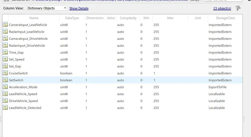
Here variables are defined and their datatypes, minimum and maximum values and storage classes are assigned.
Then the model is developed.
Model developed is
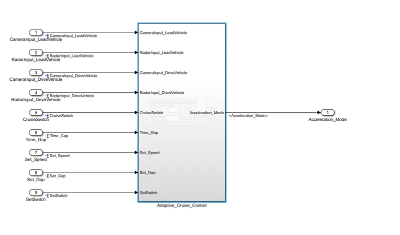
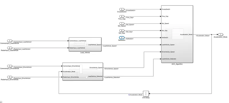
Requirements to be accomplished
Requirement 1– Lead Vehicle:
- Lead Vehicle is a vehicle which is driving in the road ahead of our drive vehicle. Two input signals (Signal Name: CameraInput_LeadVehicle & RadarInput_LeadVehicle).
- Ideally sensor fusion techniques will be deployed to process & analyze data from camera & radar. For complexity reasons, let’s not adapt to any such algorithms.
- We can simply add both the radar & camera inputs & the corresponding output is read as Speed profile output (Signal Name: LeadVehicle_Speed).
Speed data of the lead vehicle is critical in implementing the Adaptive Cruise Control algorithm.
The model for requirement 1
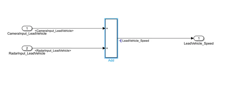
- Here the inputs CameraInput_LeadVehicle and RadarInput_LeadVehicle is added with the help of sum block.
- The output obtained is LeadVehicle_Speed.
Requirement 2 – Drive Vehicle:
- Drive Vehicle is the vehicle driven by the user & this is the vehicle which has ACC algorithm in it.
- Like the Lead Vehicle, Drive Vehicle algorithm also has 2 input signals (Signal Name: CameraInput_DriveVehicle, RadarInput_DriveVehicle) & one signal coming as an Input to this subsystem (Signal Name: Acceleration_Mode) – three inputs into this requirement in total.
- Like the above requirement, sensor fusion techniques will also be deployed here, for complexity reasons we are ignoring them.
- Two output signals come from this subsystem (Signal Name: DriveVehicle_Speed & LeadVehicle_Detected).
- Signal DriveVehicle_Speed is summation of three input signals mentioned above & LeadVehicle_Detected is renamed from Input Signal RadarInput_DriveVehicle by mere use of Signal Conversion block.
The model for requirement 2 is
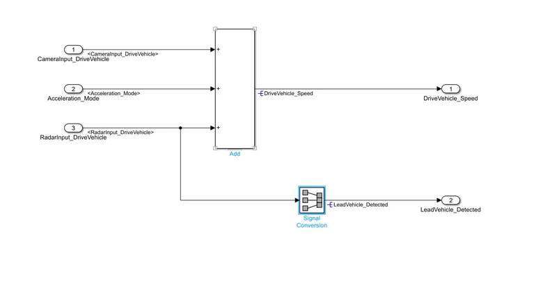
- This is the model for drive vehicle.
- Here there are three inputs: CameraInput_DriveVehicle, Activation_Mode and RadarInput_DriveVehicle.
- The LeadVehicle detected is obtained by changing the signal name of RadarInput_DriveVehicle and passing it through signal conversion block.
- The output after combining the three inputs is DriveVehicle_Speed.
Requirement 3 – Adaptive Cruise Control Algorithm:
- Adaptive Cruise Control feature has 3 major modes of operation: OFF Mode, STANDBY Mode & ON Mode. This particular requirement has to be implemented as state machine logic in Simulink.
- The input signals to this state machine system are (Signal Name: Time_Gap, Set_Speed, Set_Gap, CruiseSwitch, SetSwitch).
- Also, the output signals (Signal Name: DriveVehicle_Speed & LeadVehicle_Detected) from requirement-2 is fed back as an input signal into this state machine block.
- Additionally, output signal (Signal Name: LeadVehicle_Speed) from requirement-1 is given as an input signal to this state machine block as well.
Output from this subsystem is a signal (Signal Name: Acceleration_Mode) which governs the vehicular speed of the drive vehicle which automatically adjusts its speed & velocity to match the lead vehicle
- Under this requirement there are several subconditions.
- Inorder to so this requirement a subsystem called ACC_ALgorithm is made.
- There are eight inputs for this subsystem.
- Inside this subsystem a chart is formed to satisfy the several conditions of the vehicle system.
The model developed under this is
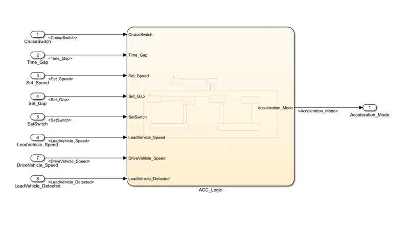
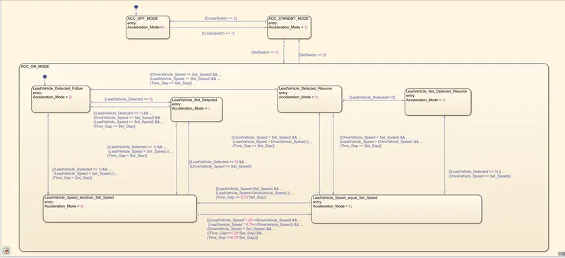
This is the logic diagram of the system
- Initially the system will be in ACC_OFF_MODE.
- According to the switching conditions the logic will move to different states.
- These states are being provided in the requirement description.
- The states are based on the position of lead vehicle and drive vehicles.
- When the cruiseswitch is on the vehicle will be in standby mode.
- When the switch is 0 then the vehicle will be in OFF mode.
After designing the stateflow chart the variables are assigned with the help of symbols pane.
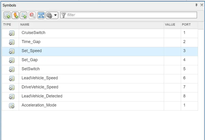
Here the variables are assigned as either input or output and the port number is also assigned.
- The variables are then assigned the same initial datatypes which were already provided.
- This is done to avoid any errors in the system during running the model.
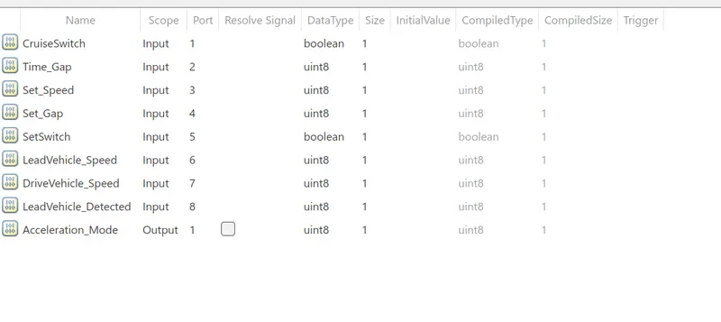
- Input and output ports are then assigned to the model.
- Names are given to the ports.
- Signals are resolved at the source of the signaland propogated where ever this is continued.
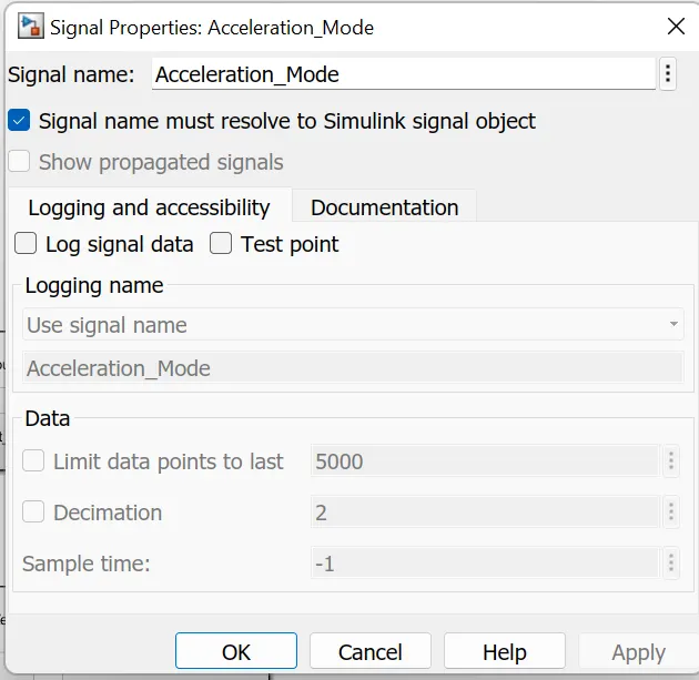
- Requirement tagging is done.
- This is done by highlighting the requirement heading and then right clicking the corresponding subsystem and selecting requirements and then select link to selection in word.
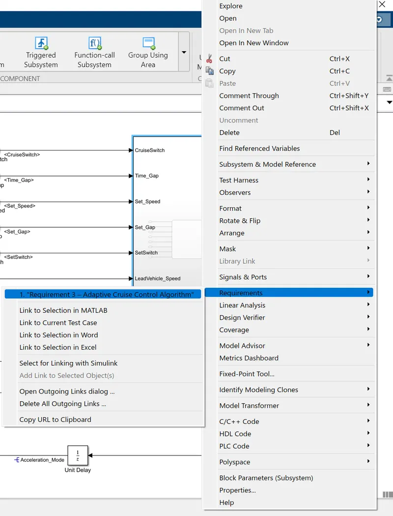
Then solver configuration and code generation settings are changed.
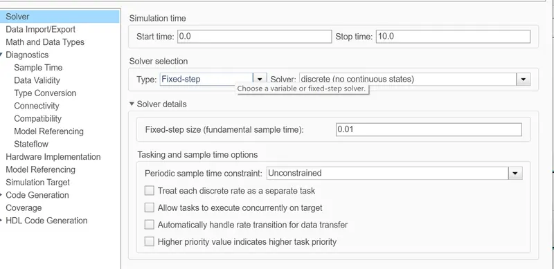
Here the solver type is change to fixed-step and discrete solver is selected.
Also sample time has been selected as 0.01sec.
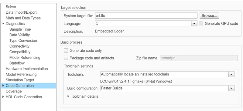
The system target file of code generation is changed to embedded coder.
- Model Advisor check is done to rectify the errors as well as to ensure the model is following MAB guidelines.
After model advisor check, the code for the model is developed.
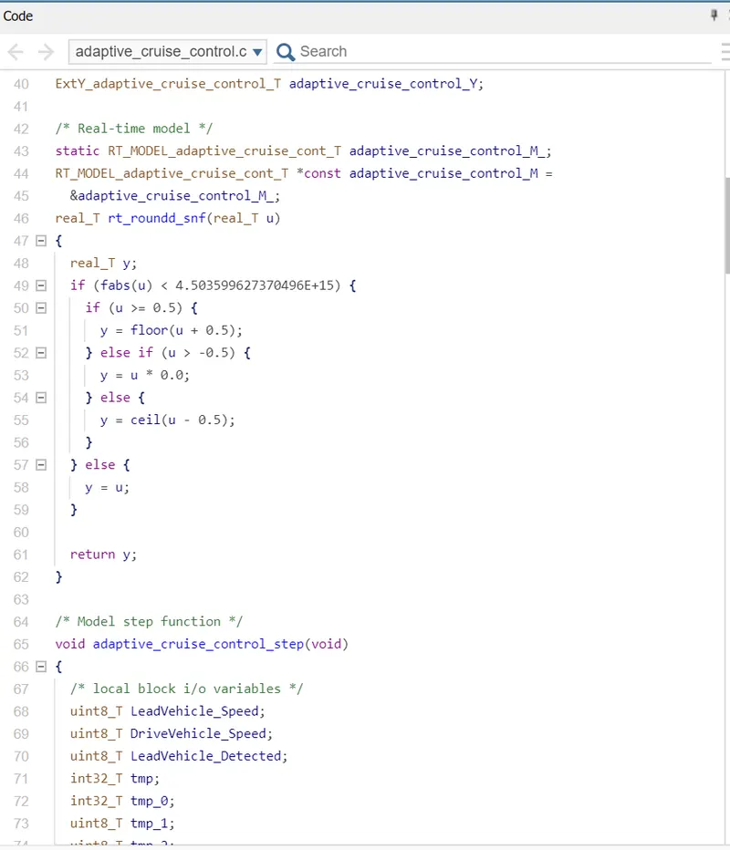
This is generated by selecting the APPS>embedded coder>Build.
By doing so a C-code folder will be formed in the same folder.
CONCLUSION
- Model is developed according to the requirement specifications given in the document.
- Variables are stored in the data dictionary.
- Chart is designed as per the given logic.
- Signals are resolved and propogated.
- Model advisor check is done.
- C-code is generated for the model design.