Project 2 Adaptive Cruise Control
Project
Adaptive Cruise Control
Aim:
- To develop the Adaptive Cruise Control feature as per the Requirement Document using MATLAB Simulink.
- To follow all the MBD related processes such as Requirement Tagging & Traceability, SLDD creation, Configuration Parameter changes, Model Advisor check & Code Generation.
Adaptive cruise control:
The main reason behind cruise control technology is to make driver relax behind the wheel. Because of this, their driving experience becomes safer, thrilling and also saves the fuel consumption. By monitoring other vehicles and objects on the road, adaptive cruise control enables a safe and comfortable driving experience. It helps the driver keep a steady vehicle speed at a given moment. The driver can set their preference regarding certain factors, such as the distance to the car in front, driving mode. Together with information about speed limits, road curvature, accidents data and more, these choices influence the automatically selected speed. As less expensive sensors reached the market, adaptive cruise control is steadily becoming a standard feature in new vehicles today.
In slow-moving traffic, it automatically stops or starts vehicle movement under driver supervision. The car will brake and accelerate on its own, while maintaining a safe distance from the vehicle in front. Intelligent cruise control can automatically adjust the set speed to the newly detected speed limit when the driver is passing a speed limit sign. This is done by fusing camera observation and map data to provide reliable speed restriction information.
Radar-based systems work by placing radar-based sensors on or around plastic fascia's to detect your vehicle's surroundings. Each radar sensor works together to create a comprehensive picture of the vehicle's proximity to other cars or potentially hazardous objects. This type of sensor can look different depending on the design and model of the car.
ACC that uses sensory data to predict the actions of neighbouring vehicles. This means that your car might slow down to brake for another vehicle suddenly switching lanes and, in doing so, promotes passenger safety.
Overall Model:
As Per the requirment had created a simulink model for adaptive cruise control features.
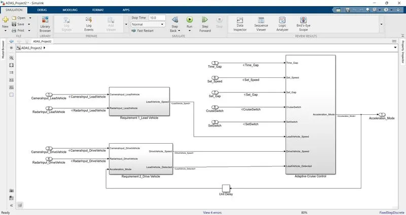
They are consist of Three Requirement subsystem,
- Lead Vehicle subsystem.
- Drive Vehicle subsystem.
- Adaptive Cruise Control Subsystem.
Requirment 1:
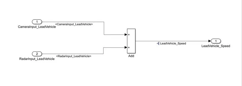
As per the Requirement 1, the Input from CameraInput_Leadvehicle signal and RadarInput_LeadVehicle signal are sum to get the LeadVehicle_Speed output.
Requirement 2:
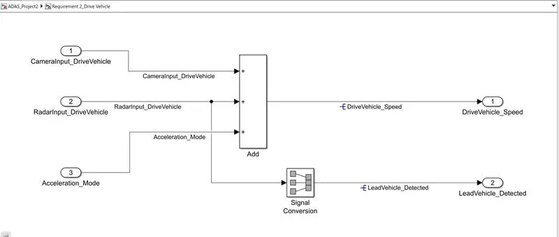
For Drivevehicle_Speed calculation we are Adding, Camerainput_DriveVehicle, Radarinput_Drivevehicle and Acceleration_Mode feedback from cruise control algorithm,
The outputs from this subsystem as DriveVehicle_Speed and Lead_Vehicle_Detected by propagating Radarinput_DriveVehicle into signal conversion block.
Requirement 3:
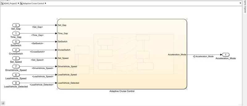
In this subsystem we are using a state flow logics to implement the requirements 3a,3b, 3c,3c(i),3c(ii),3c (iii),3c(iv),3c(v),3c(vi).
The inputs for the state flow are,
- Time_Gap
- Set_Speed
- Set_Gap
- CruiseControl
- Setswitch
- DriveVehicle Speed from Requirement 2
subsystem - LeadVehicle Speed from Requirement 1 subsystem
- LeadVehicle Detected from Requirement 2 subsystem.
The output from this subsystem is,
- Acceleration_Mode-Based on the LeadVehicle Speed the Acceleration_Mode udjust its controlling accaleration given output to maintain constant speed.
State Flow Logic (Adaptive Cruise Control):
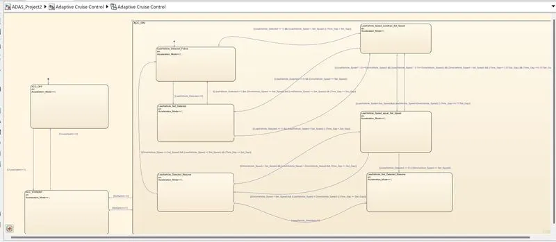
In this logic we had created three modes of operation as,
1. ACC OFF mode.
2. ACC STANDBY mode.
3. ACC_ON mode.
In ACC_ON mode we have further 6 modes of operations as,
• LeadVehicle Detected_Follow (Default).
• LeadVehicle_Not_Detected.
• LeadVehicle_Detected_Resume. • LeadVehicle_Not_Detected_Resume.
• LeadVehicle_Speed_lessthan_Set_Speed. • LeadVehicle_Speed_equal_Set_Speed.
All these modes of operations are modelled as per the given as mentioned in requirements section.
SLDD File creation:
For all the input and output signals resolved and propagated in this model are declared in the SLDD file created as shown below,
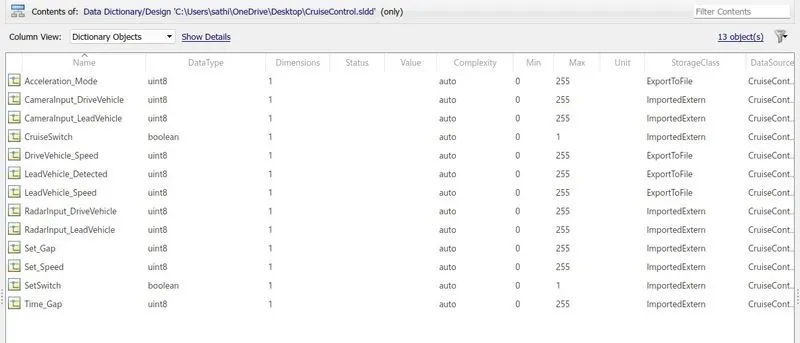
The signal parameters are declares as per the SLDD datatype requirements mention earlier.
The code generated from output signals are stored in ADAS_CruiseControl.h and ADAS_CruiseControl.c files.
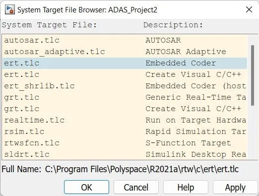
Embedded Coder implementation:
the model will be finished and to do some step for the based on requirement.
Result:
After compiling the model we are getting some matlab installation area errors occur on model creation so justifies our logic on modelling for requirements are correct.
Note:
The model advisor check and code generation are does not created because my software installation have some error so please ignore the exact result try to justify created model blocks and proper requirement creation i clear all the probs for future