Project 2
2. Design a simply supported gantry girder to carry electric overhead travelling crane
Given:
Span of gantry girder = 7 m
Span of crane girder = 9 m
Crane capacity = 250 kN
Self-weight of trolley, hook, electric motor etc. = 40 kN
Self-weight of crane girder excluding trolley = 100 kN
Minimum hook approach = 1.0 m
Distance between wheels = 3 m
Self-weight of rails = 0.2 kN/m
Ans.
Solution:
Maximum moment due to vertical load
weight of trollley + crane capacity = 40 + 250 = 290 kN
Self-weight of crane girder excluding trolley = 100 kN
For maximum reaction on gantry girder, the moving load should be as close the gantry girder as possible.
This load is transferred to gantry girder, through two wheels, the wheel base being 3m.
So load on gantry girder from each wheel = 307.77/2 = 158.88 KN
Factored load = 158.88 x 1.5 =230.83 KN
Maximum moments due to moving loads occur under a wheel when the c.g of wheel load &
The wheel are equidistant from the ccentre of girder, as shown below.
Max. moment, Me = 148.40 x 2.25 = 333.90 KN-m
Moment due to impact = 0.25 x 333.90 = 83.47 KN-m
Assume self weight of girder = 2KN-m
Dead load due to self weight + rails = 2+0.2= 2.2 KN-m
Factored DL = 2.2 x 1.5 = 3.3 KN-m
Moment due to DL = = 20.21 KN-m
Factored moment due to all vertical loads,
Mz = 333.90 + 83.47 + 20.21 = 437.58 KN-m
Maximum moment due to Lateral force:
Horizontal force transferred to rails = 10% of weight of trolley plus load lifted = (10/100) x (250+40) = 29 KN
This is distributed over 4 wheels.
So, horizontal force on each wheel = 29/4 = 7.25 KN
Factored horizontal force on each wheel = 1.5 x 7.25 = 10.875 KN
For maximum moment in gantry girder the position of loads is same as earlier except that it is horizontal, hence byproportioning we get.
My = (10.875/230.83) x 333.90 = 15.73 KN-m.
Shear force:
For maximum shear force on the girder, the trailing wheel should be just on the girder as shown below.
Vertical shear due to wheel loads = 230.83 + (230.83 x 3) / 7 = 329.75 KN
Priliminary Section:
Minimum economic depth, L/12 = 7000/12 = 583.33 mm
Width of the compression flange may be taken as (1/40) to (1/30) of span
So, flange width can be taken, L/40 = 7000/40 = 175 mm to L/30 = 7000/30 = 233.33 mm.
Let us try a ISWB 600 with ISMC 400 on compression flange.
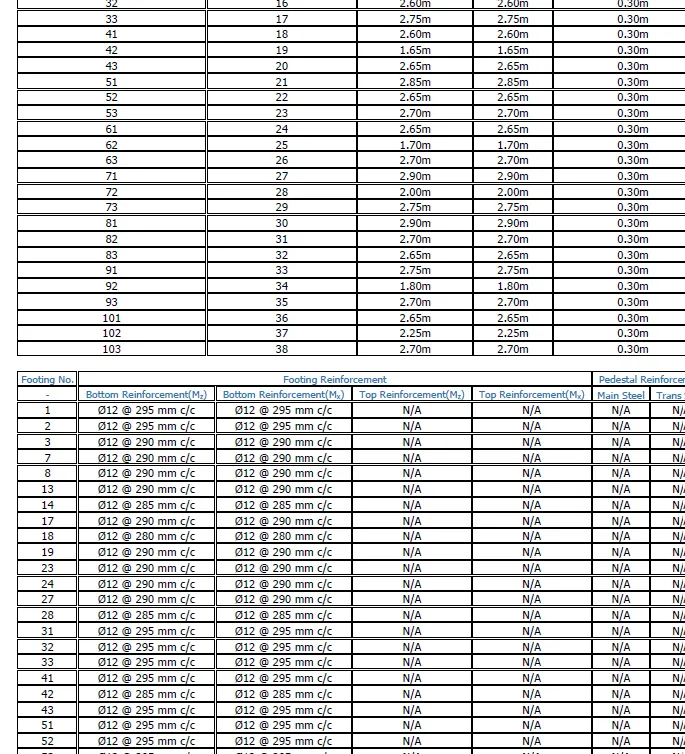
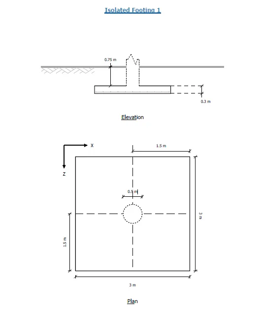
Excel Calculataion part is attached
1. PROCEDURE
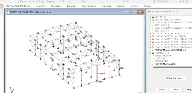
ROOF SLOPE CALCULATION
- Roof Slope = 1 in 12
- Width, b = 30 m
- X / (b/2) = 1/12
- X = (30/2) / 12 = 15/12
- X = 1.25 m
Total height =9 +1.25 =10.25
Calculation of Design Loads
1) Calculation of Dead load:
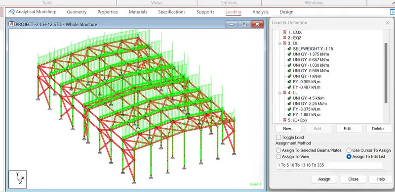
- UDL on Rafter (Main frame):
- Weight of roof sheeting = 5 Kg/m2
- Weight of sag rods and braces = 5 Kg/m2
- Collateral load = 10 Kg/m2
- Total load = 20 Kg/m2 = 0.2 KN/m2
- UDL on Rafters:
- Bay spacing = 6m
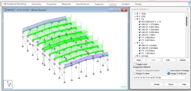
- UDL = 0.2 X 6 = 1.2 KN/m
- UDL on Rafters from purlin:
Choose suitable purlin section for weight of purlin (IS-811)
Say Z = 270 X 75 X 20 X 2.55 = 8.77 Kg/m
weight on rafters from purlin = (Number of purlin X Length of purlin)/Length of rafter
= ( 5 X 6 X 8.77)/15
= 17.54 Kg/m = 0.175 KN/m
- UDL on main frame = 1.2 + 0.175 = 1.375 KN/m
- UDL on gable frame = 1.375/2 = 0.687 KN/m
UDL on Column (Main frame):
- Weight of side wall sheeting = 5 Kg/m2
- Weight of sag rod and braces = 5 Kg/m2
- Load from sag rods & braces = 10 Kg/m2 = 0.1 KN/m2 = 6 X 0.1 = 0.6 KN/m
- Weight of grit (270 X 75 X 20 X 2.55) = 8.77 Kg/m
- on column = (5 X 6 X 8.77)/6 = 43.85 Kg/m = 0.438 KN/m
- Total Load = 0.6 + 0.438 = 1.038 KN/m
UDL on Column (Gable frame):
- Total load = 1.038/2 = 0.565 KN/m
- Load on wind column:
- Load from sheet and sag rods = 0.1 X 6 = 0.6 kN/m
- Weight of grits (230 X 75 X 20 X 2) = 6.32 KG/m
- Load on wind column = (6X 6.32 X 6)/6 = 37.92 Kg/m = 0.38 KN/m
- Total load = 0.6 + 0.38 = 0.98 KN/m
Dead Load on eave strut & Gutter
Point load:-
- Weight of Eave strut = CS 270 X 75 X 20 X 3.15 = 10.7 Kg/m
- Weight of eave gutter = 0.25 X 0.25 X 0.001 = [0.25 + 0.25 + 0.25] X 0.001 X 7850 =5.89 Kg/m
- Load due to eave strut & gutter = 10.7 + 5.89 = 16.59 Kg/m
- Load due to eave strut & gutter (Main frame) = 16.59 X 6 = 99.54 Kg = 0.995 KN
- Load due to eave strut & gutter (Gable frame) =0.495kn
2) Calculation of Live load:
- Live load on roof = 0.75 KN/m2 (IS 875- II)
UDL on Rafter:
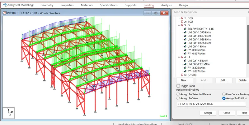
- Main frame rafter = 0.75 X 6 = 4.5 KN/m
- Gable frame rafter = 0.5 X 4.5 = 2.25 KN/m
- Eave gutter (250 X 250 X 1mm)
Load due to weight of water in gutter:
- Main frame = [0.25 X 0.25 X 9 X 6] = 3.375 KN
- Gable frame = [0.5 X 3.375] = 1.687 KN
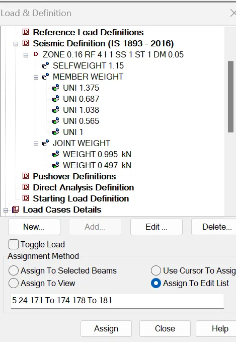
3) Seismic Load
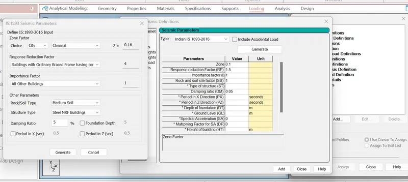
As per IS: 1893 - 2016
- Seismic zone - III - Z = 0.16
- Reduction factor - 4.0
- Impartnace factor - 1.0
- SS - 3.0
- 25% of Live Load on roof considered for calculation of seismic forces.
- 100% of collateral load on roof considered for calculation of seismic forces.
- 50% of (Live load + Collateral load) on mezzanine floor considered for calculation of seismic forces.
- 100% of Dead load considered for calculation of seismic force
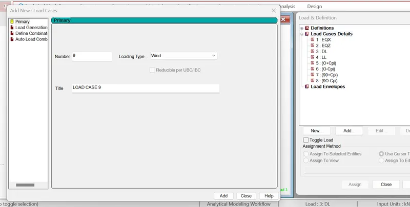
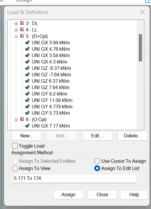
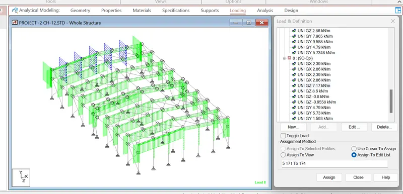
4) Wind - calculation Excel file is attached
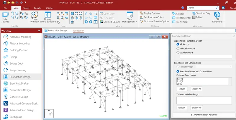
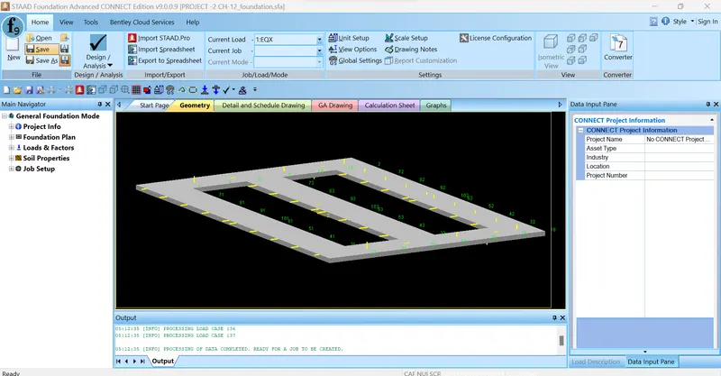
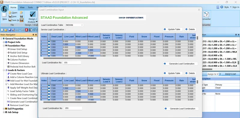
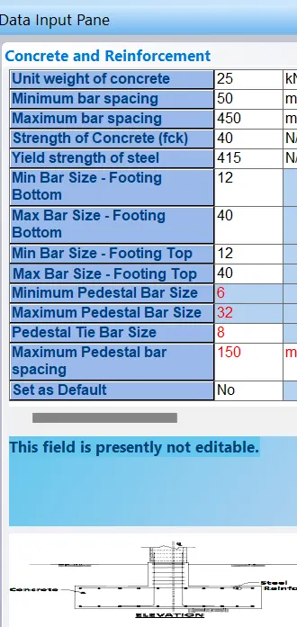
Staad Foundation