Project 2
- Design a DC power supply using PFC circuit for general purpose applications with 350V dc output and load in the range of 0-7A. The supply should meet the harmonic standard limits for input power quality such that current THD limits are satisfied with input power factor >0.97 value. The input side is connected to single phase grid with parameters as 230V, 50Hz.
Design the supply to give following specifications:
- Component selection and justification
- Passive component designs including filters
- Controller design
- Simulation results
- Validation with the design criterion
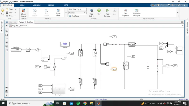
The simulink model is shown below:-
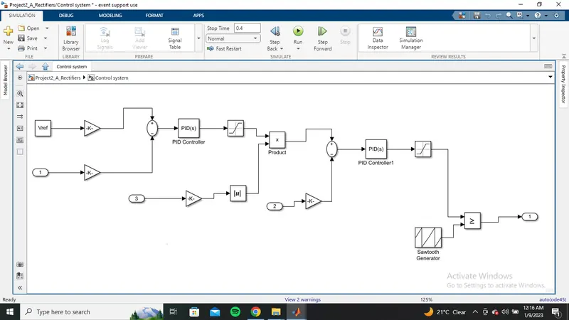
subsystem:-
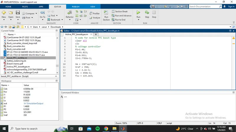
The code used in simulation is shown below:-
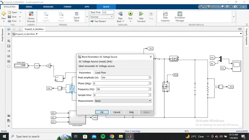
The parameters used in the simulation is shown below:-
AC voltage source:-
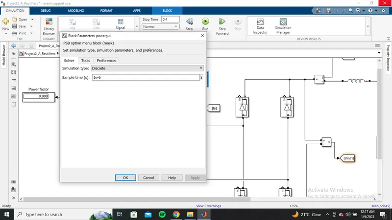
powergui:-
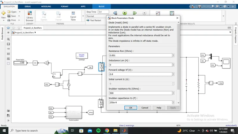
Diode:-
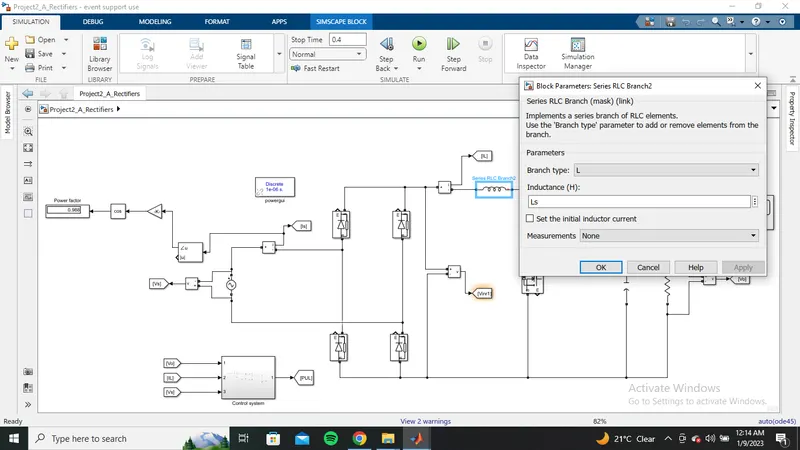
inductance:-
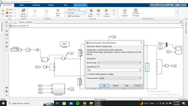
Cdc load:-
R load:-
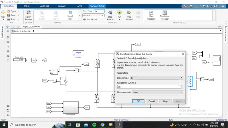
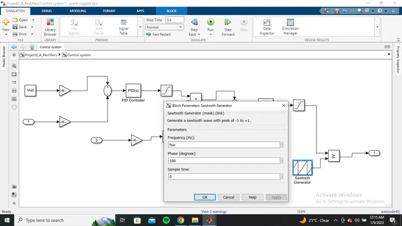
Sawtooth generator:-
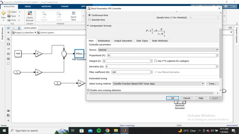
pulse generator:-
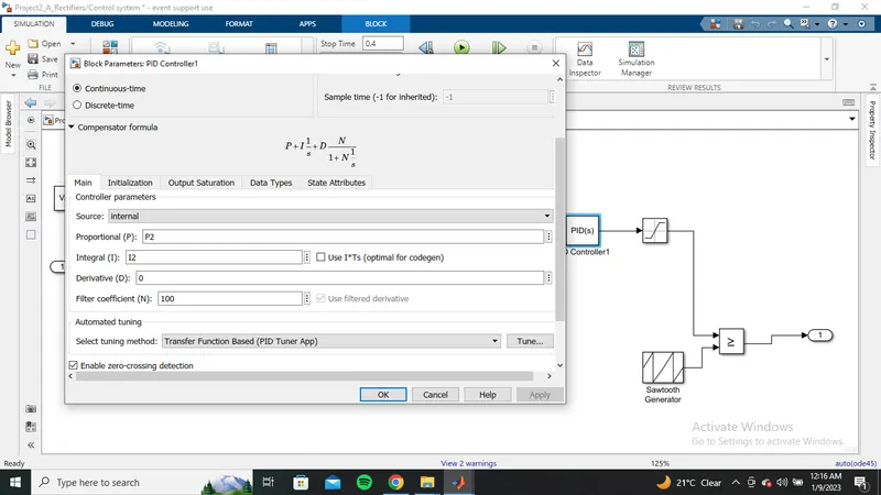
pulse generator1:-
with the above parameters now save and Run the simulation with stop time as 0.4
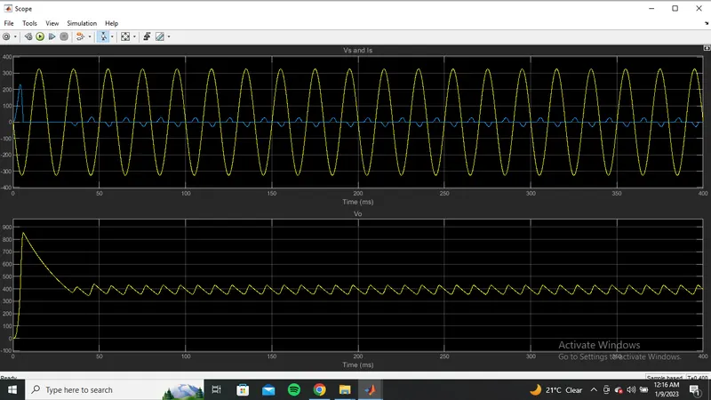
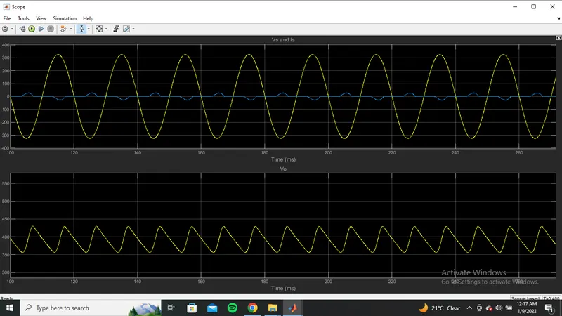
Output waveforms are shown below:-
zoomed out:-
zoomed in:-
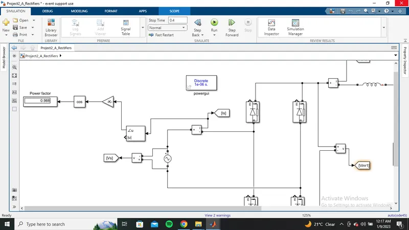
Power factor:-
Part B:
Design a high-performance high voltage DC power supply for 15 kV dc output and load in the range of 0-10A. The supply should meet the harmonic standard limits for input power quality such that current THD limits are satisfied with input power factor >0.98 value. The input side is connected to three-phase LV grid with parameters as 11kV (line-line), 50Hz.
Design the supply to give following specifications:
- Component selection and justification
- Passive component designs including filters
- Controller design
- Simulation results
- Validation with the design criterion
- Typical output voltages for high voltage power supplies are 1kV to 360kV, although ranges of 62V to 500kV are offered. Spellman's range of output power spans from less than a watt to over 200 kilowatts.
- HVDC allows power transmission between AC transmission systems that are not synchronized. Since the power flow through an HVDC link can be controlled independently of the phase angle between source and load, it can stabilize a network against disturbances due to rapid changes in power
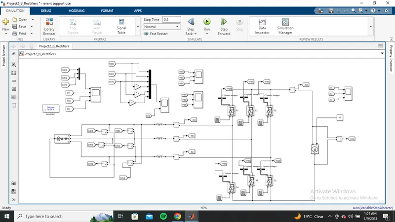
The simulation model is shown below:-
Matlab code used in the simulation is shown below:-
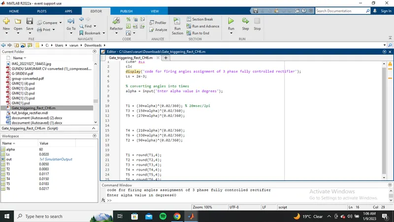
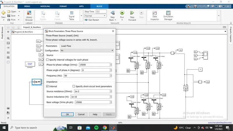
The parameters used in the simulation is shown below:-
Three phase source:-
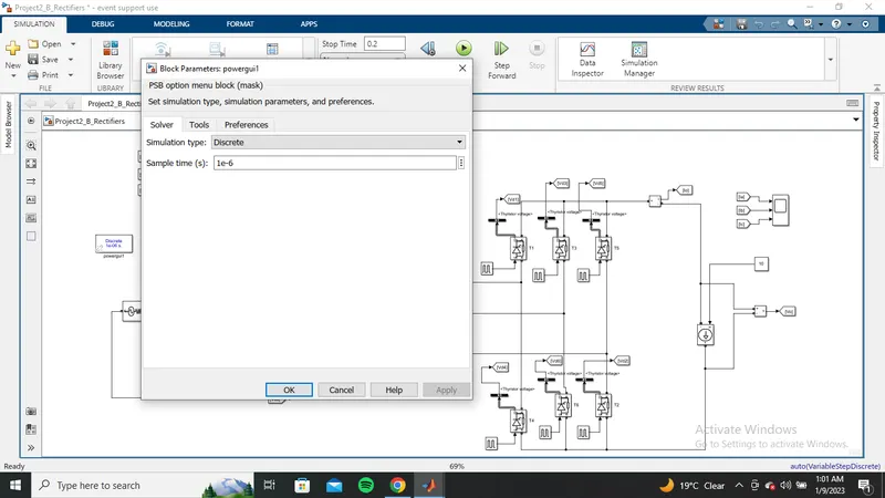
power gui:-
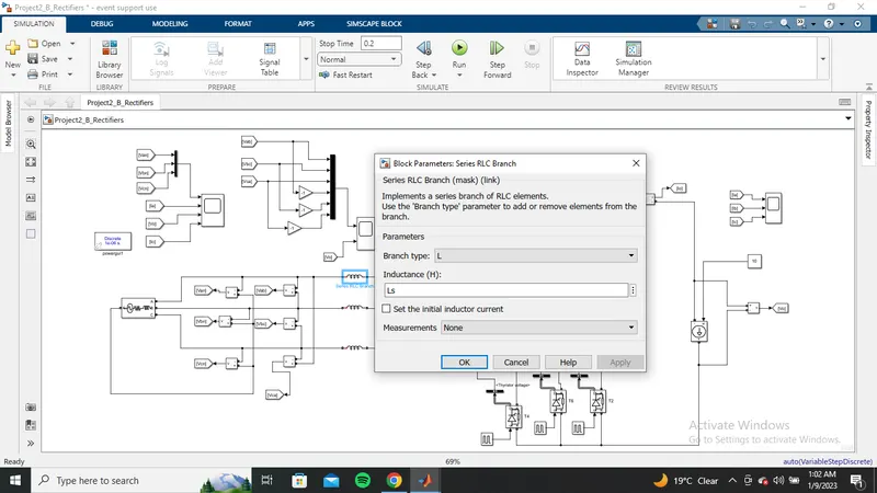
Ls:-
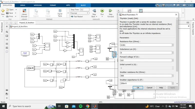
Thyristor:-
pulse generator:-
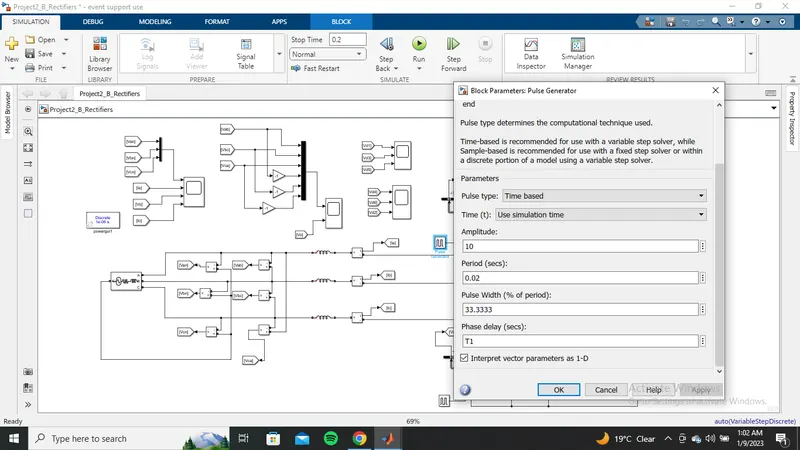
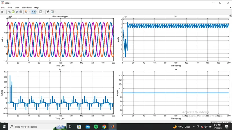
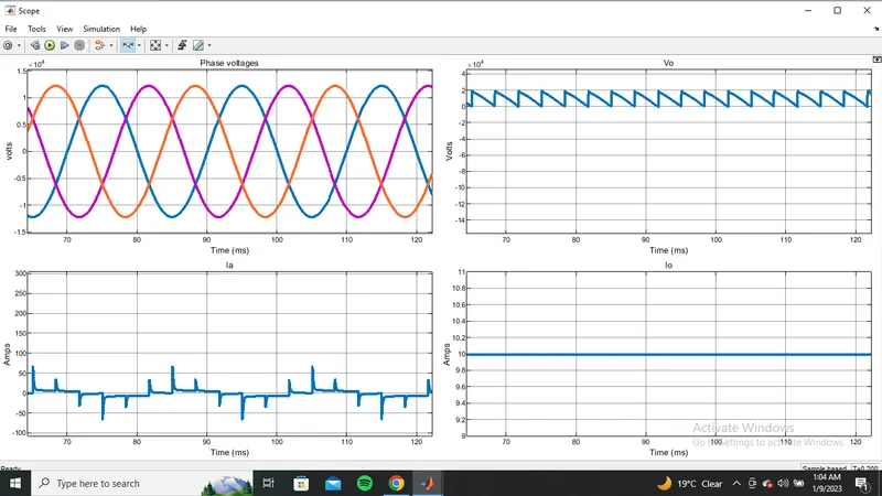
with the above parameters now save and Run the simulation with Stop time as 0.2
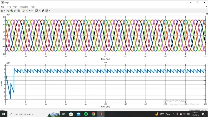
output waveform are shown below:-
zoomed out:-
zoomed in:-
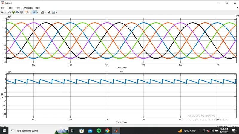
zoomed out:-
zoomed in:-
The Three-phase PFC is not discussed properly in the videos and not in the scope by the instructor so designed an fully controlled HVDC transmission.