Project 1
1)BUCK CCM:-
Given data:-
input voltage :-40-50V
output volatge :- 30V
power:-500W
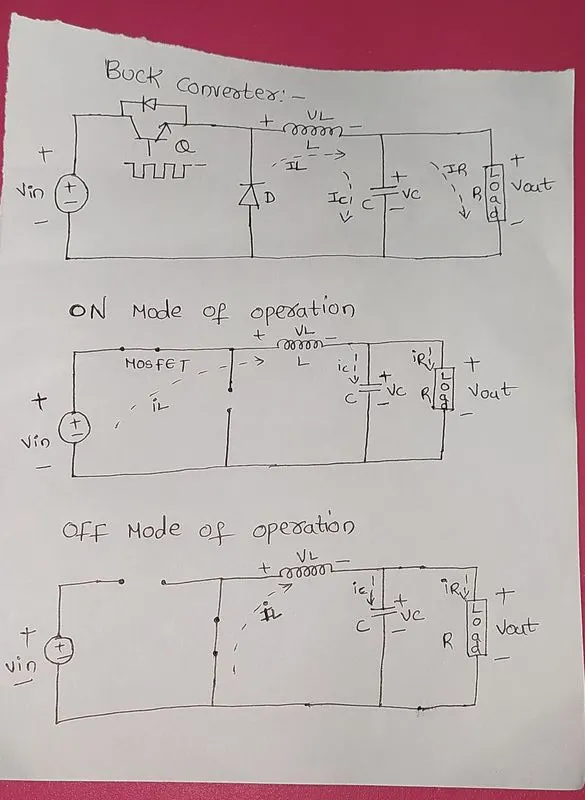
The schematic diagram of BUCK CCM converter shown below:-
And ON and OFF modes of operation:-
Basics of DC-DC converter:-
A DC to DC converter is a power electronics circuit that efficienty converts a direct current from one voltage to Another voltage.
In this now we are discussing about BUCK converter CCM:-
Buck converter step down a DC voltage from the input to the output. We use diode, mosfet and inductor and capacitor and resistor and input voltage we use MOSFET in the converter for switching and inductor and capacitor of storing the energy and we have a Resistive load.
WE have two modes of operation:-
ON mode and OFF mode
ON mode of operation:-
In this mode MOSFET is ON or (switch is closed) and diode is open in this operation the current flows throught inductor and capacitor and R load and return back to Vin in this operation inductor and capacitor they both stored the energy.
OFF mode operation:-
In this mode MOSFET is OFF (or) switch is opened in this as we know inductor stored the energy now in this the role amy played by the inductor in off mode operation the inductor acts as source and as per lenz law inductor does not allows sudden changes in load nwow the stored energy or (voltage) flows through capacitor and resistor and throught diode .
CCM(Continuous conduction mode);-
We can know weather the circuit is in CCM OR DCM by inductor current in CCM mode the inductor current does comes to zero it is in continuous operation and where as in DCM mode the inductor current comes to zero and it from zero it starts again.
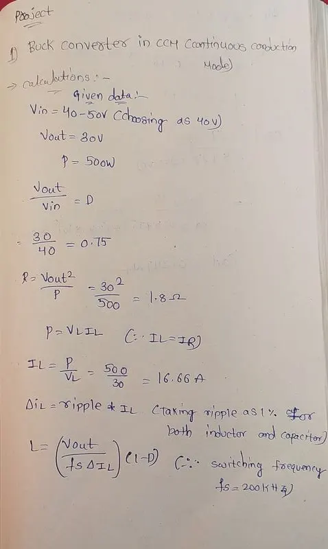
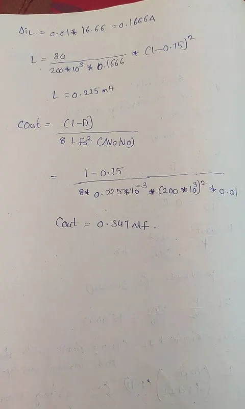
The required calculations are shown below:-
The simulink model shown below:-
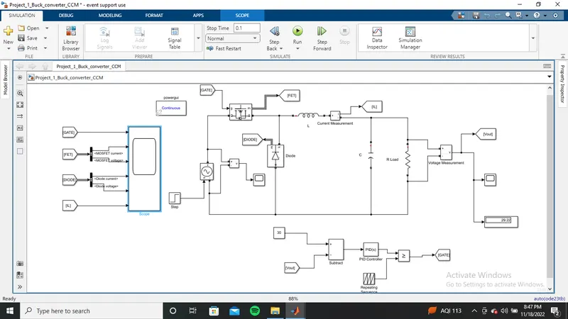
The paramerters we used in simulation:-
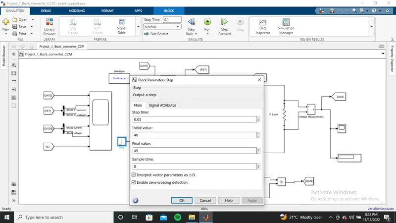
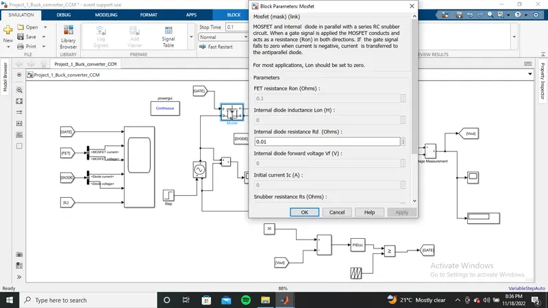
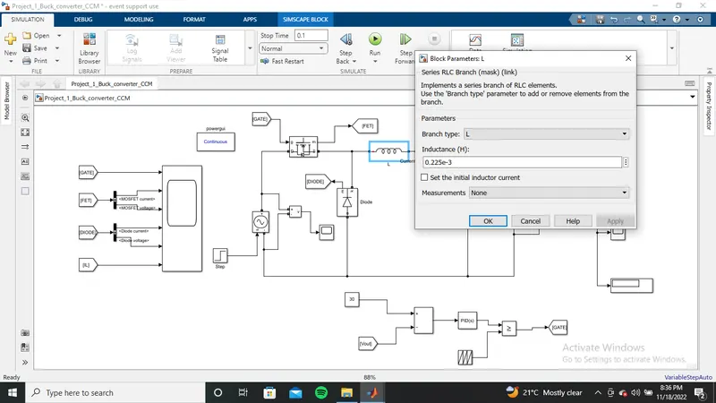
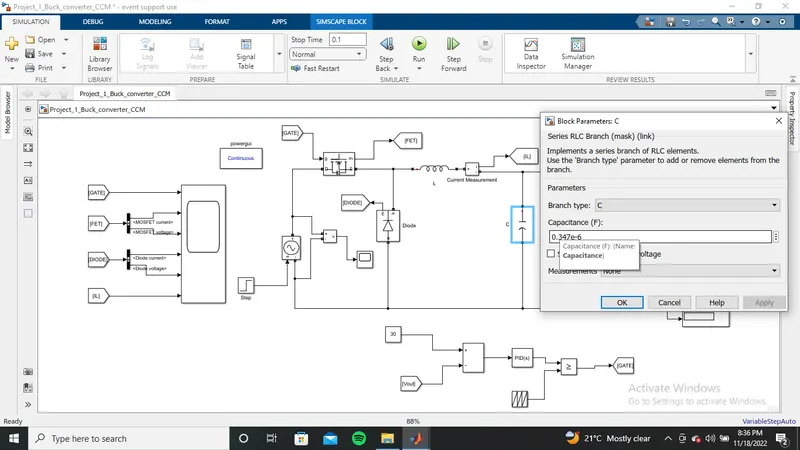
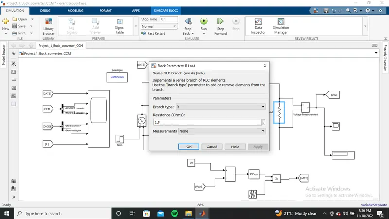
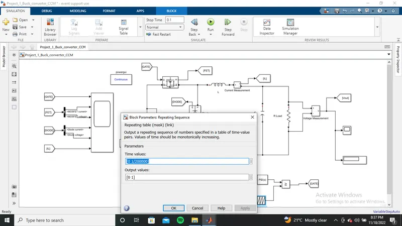
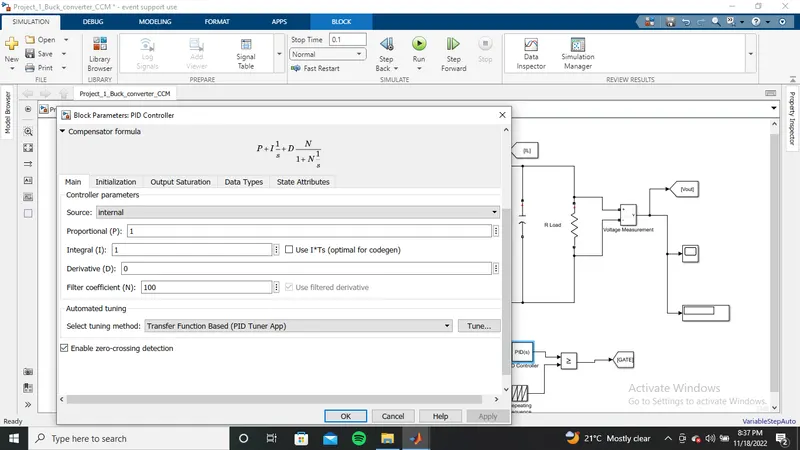
after desiging with all parameter save and Run the simulation.
output waveforms are shown below:-
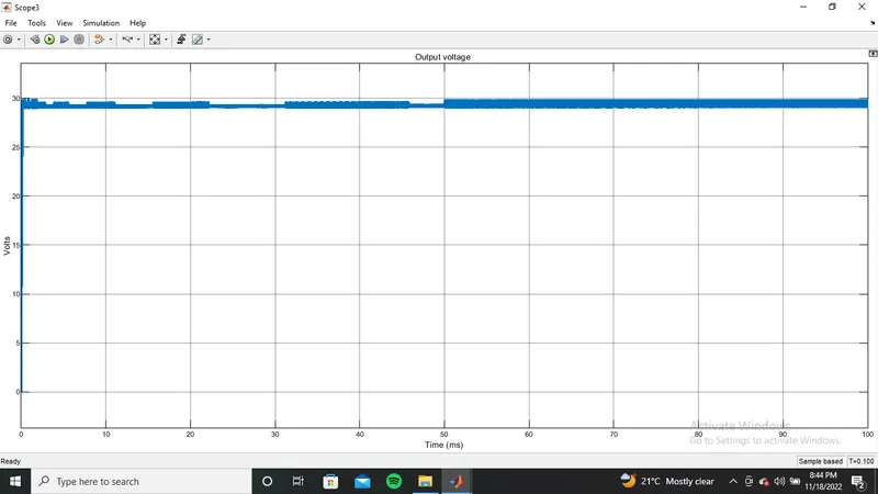
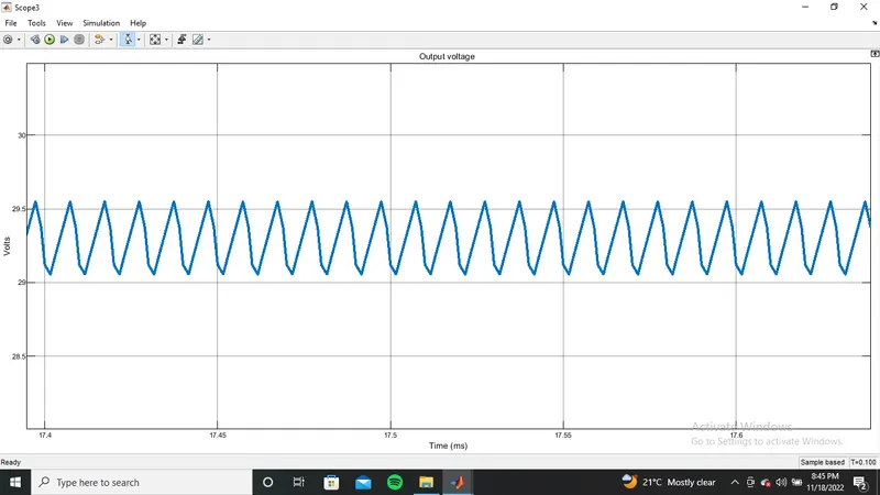
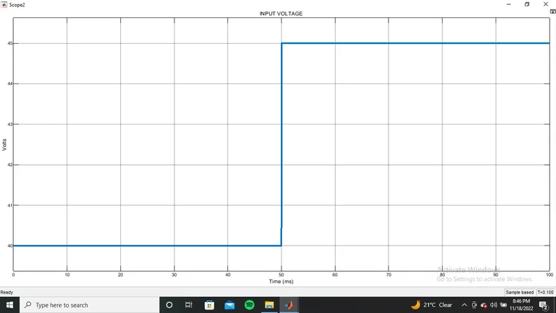
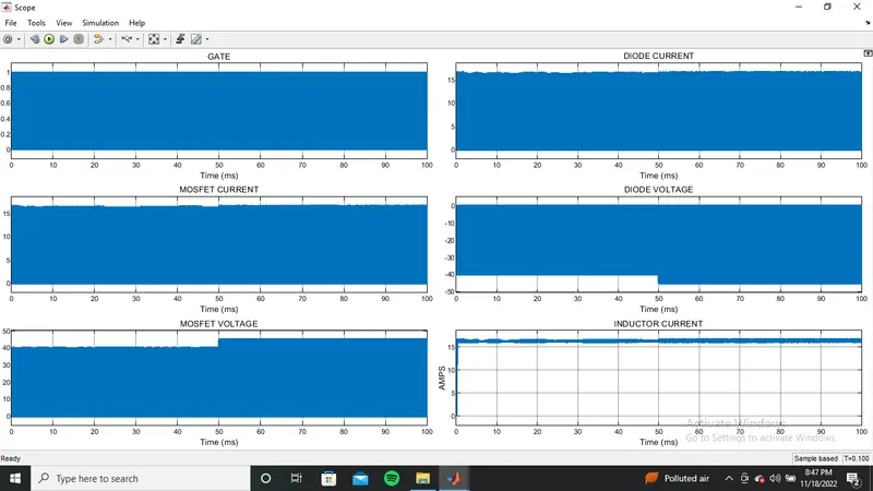
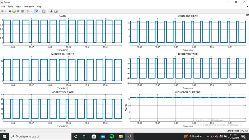
Hence the designing of Buck converter CCM with given paramerters has done successfully.
2)BOOST CCM:-
Given data:-
input voltage :- 20-30V
output voltage :- 40V
power:- 600W
The schematic diagram of boost converter:-
And ON and OFF mode of operation:-
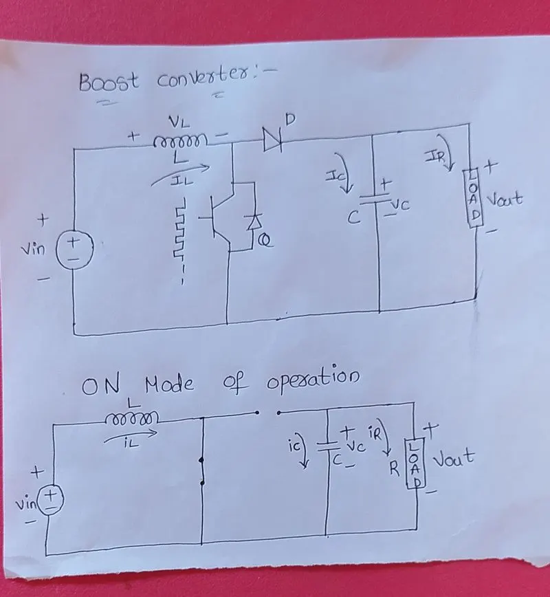
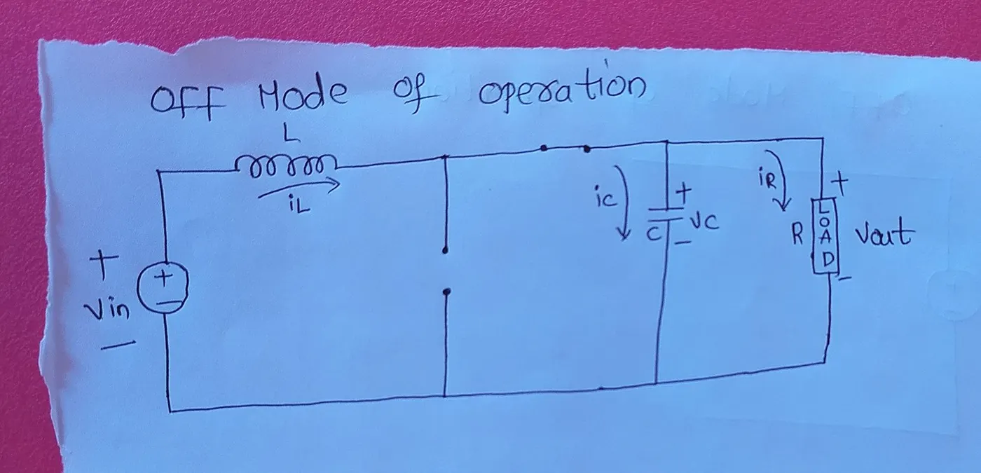
BOOST converter also know as step up DC-DC converter
The calculations are shown below:-
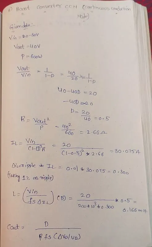
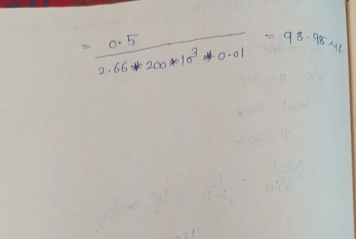
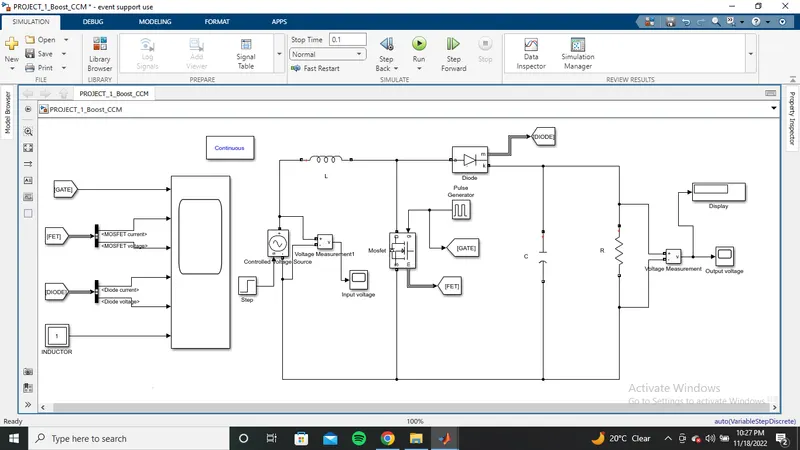
THE simulink model is shown below:-
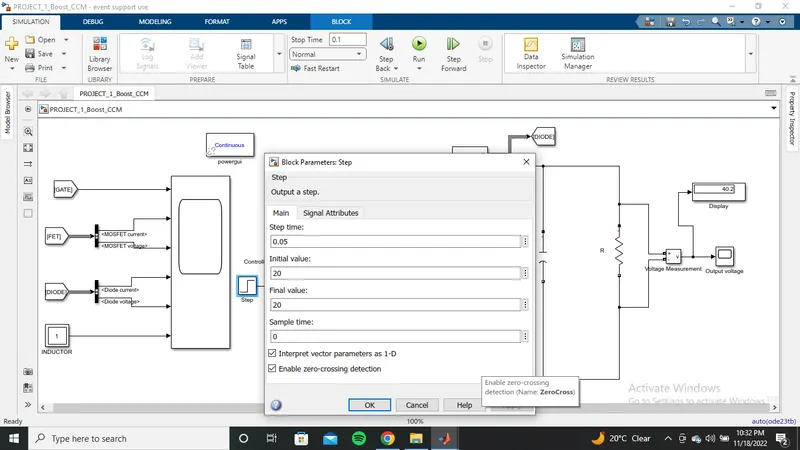
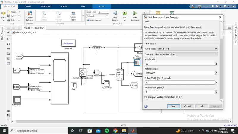
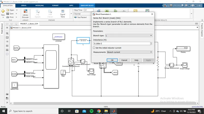
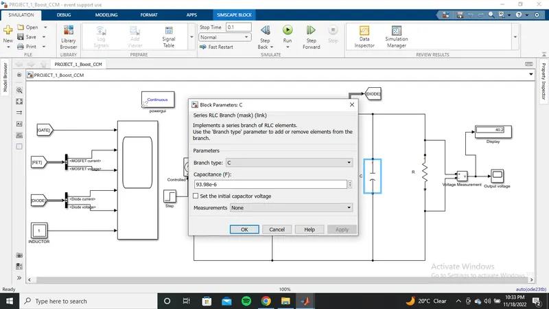
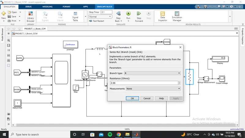
The parameters used in simulation are shown below:-
 Ou
Ou
Now save and RUN the simulation
Ouput waveforms are shown below:-
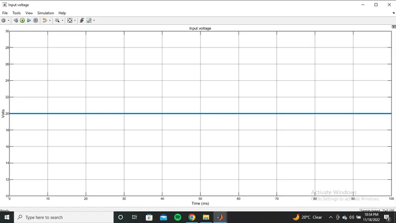
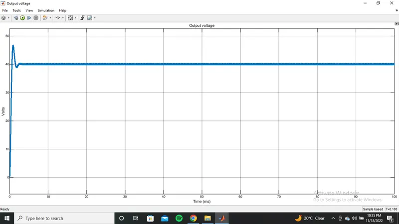
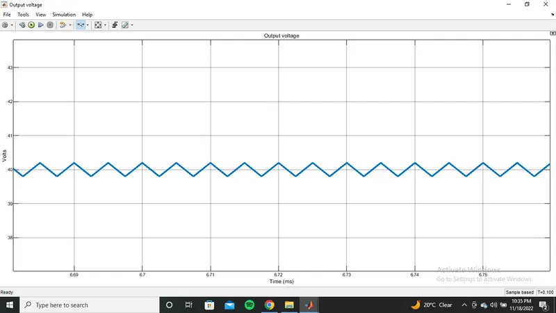
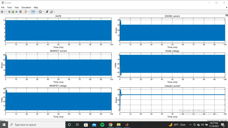
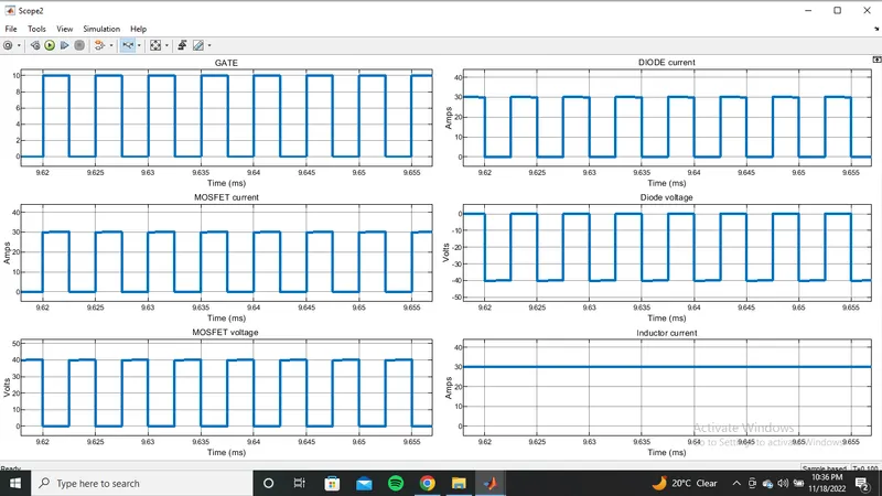
Hence the designing of Boost CCM converter with given paramertes has done successfully.
10)BUCK CCM:-
Given data:-
input voltage:-400-500V
Output voltage:-300V
Power:-5KW
The schematic diagram shown below:-
And ON nad OFF modes of operation:-
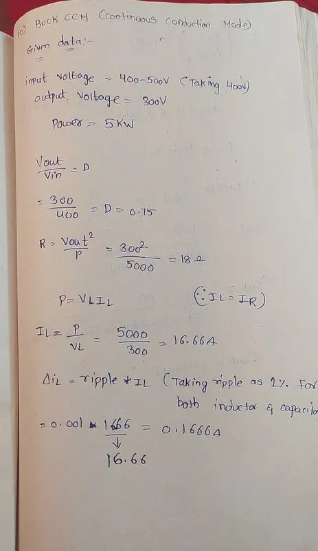
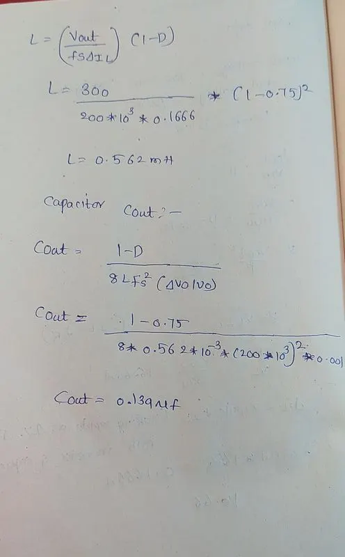
The required calculations are shown below:-
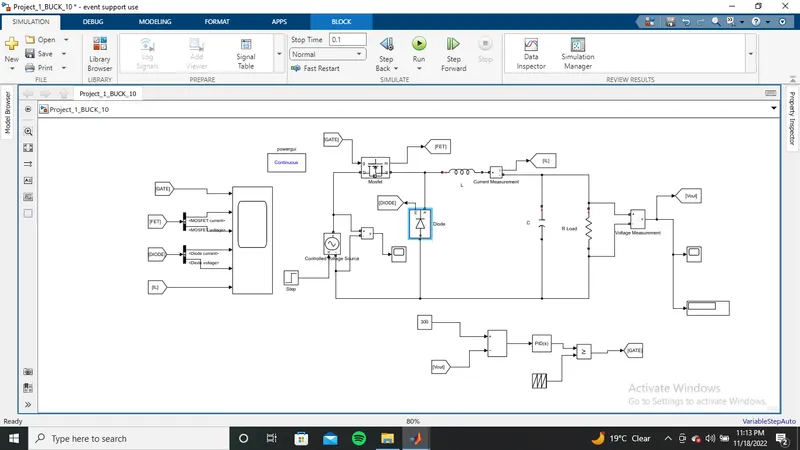
AS per schemaitc diagram we have designed a simualtion model:-
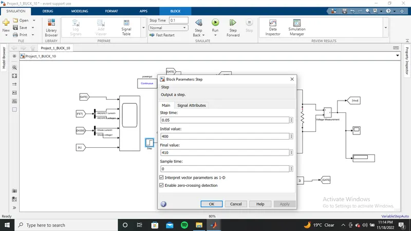
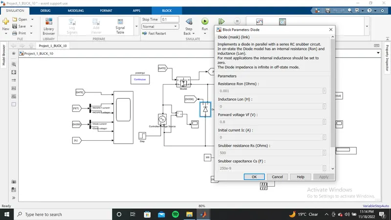
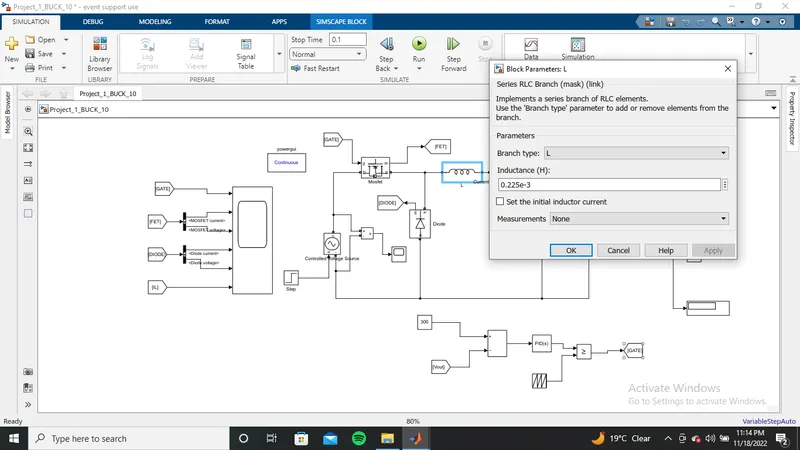
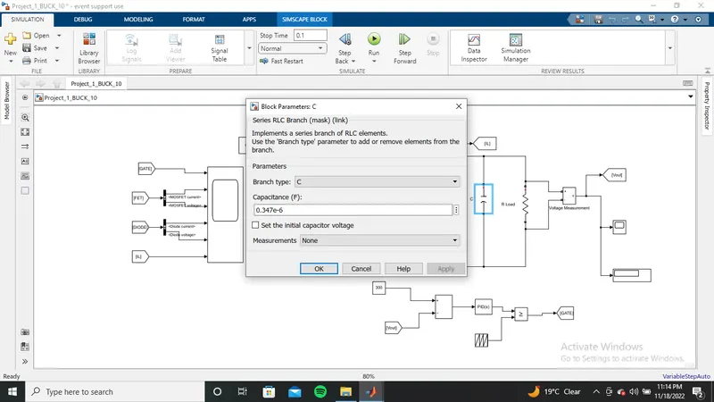
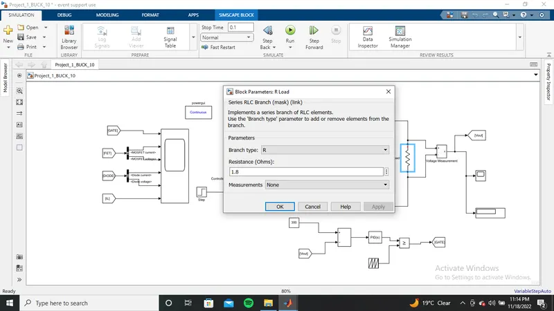
The parameters we used in simulation is shown below:-
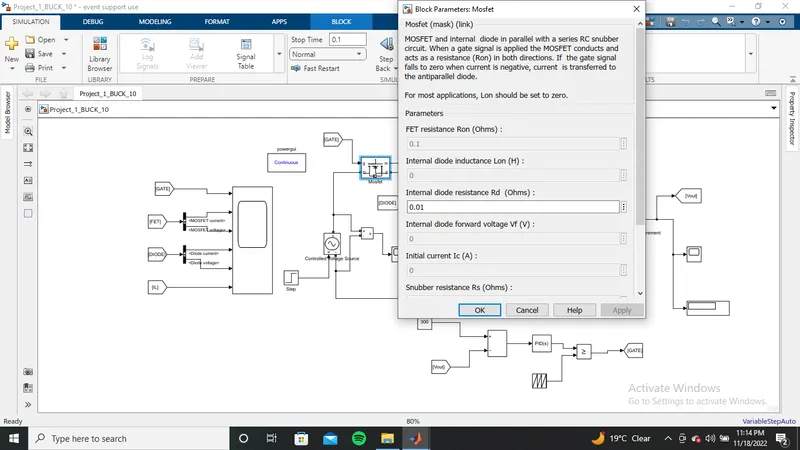
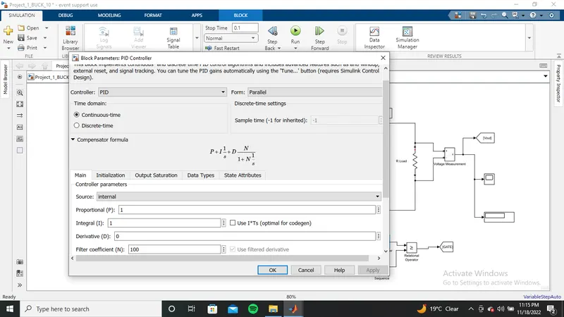
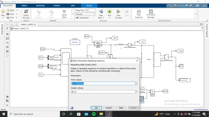
Now save and RUN the simulation
outputs are shown below:-
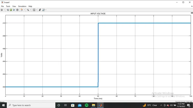
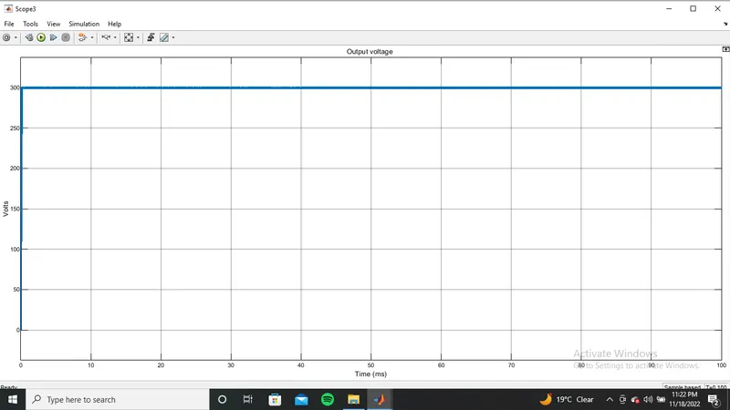
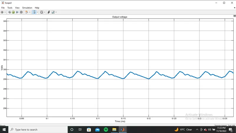
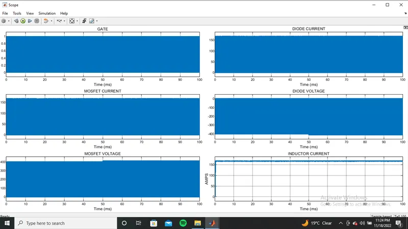
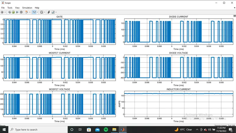
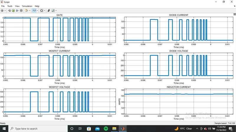
Hene we the designing of BUCK CCM converter with given paramerters has done successfully.