Project 2
PART A :- DC power supply using PFC circuit for general purpose applications with 350V dc output and load in the range of 0-7A
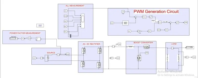
1) SIMULATION
2) ALL GRAPHS
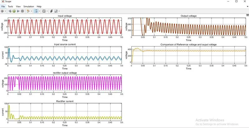
By observing the above graphs i achieved the desired output voltage i.e 350v dc average value
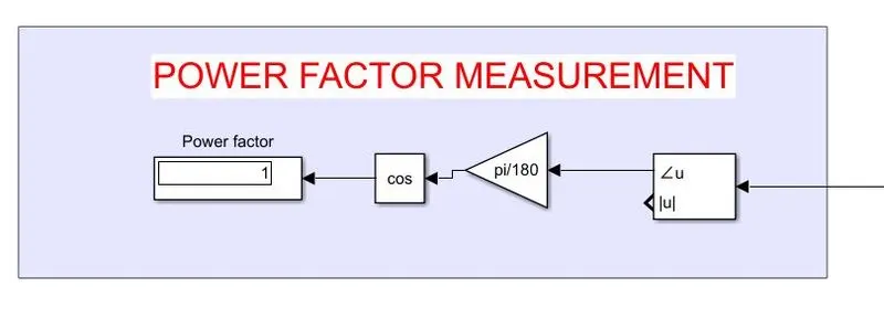
3) power factor :- satisfied with input power factor >0.97 value
4) load in the range of 0-7A:- i got the range
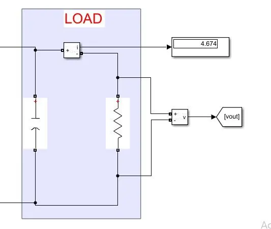
5) Without the pwm circuit we didnt achive the desired output so the this curcuit is very important.
6) Give the difference in both power supplies in terms of cost, control complexity, degrees of freedom, additional features and efficiency.
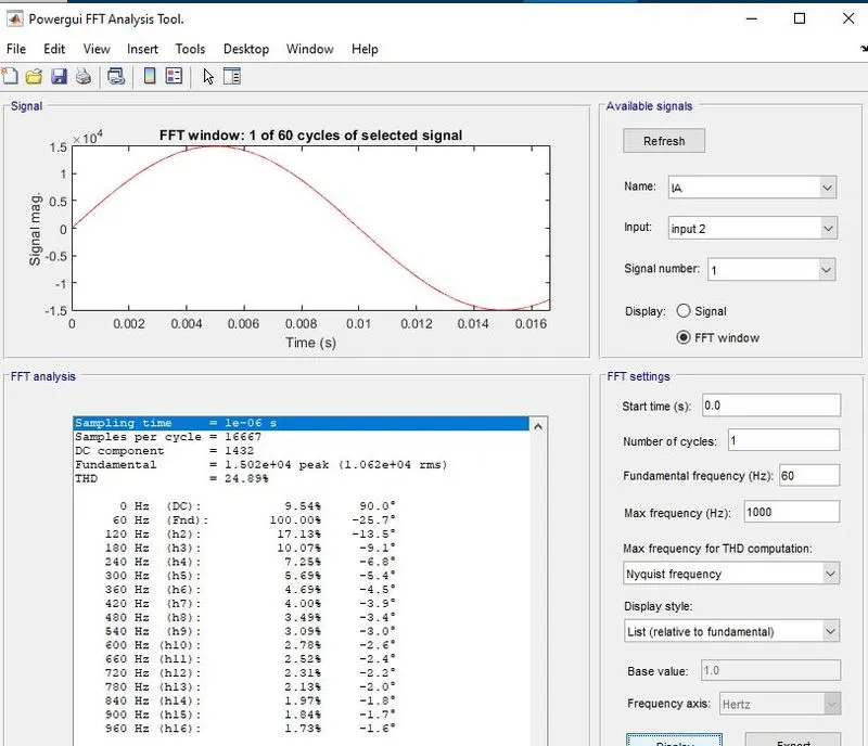
7) THD=24.89% this value is not as per the IEEE standard it should be near about 8% by implementing extra harmonic filters we can also minimize this value
answer :- cost of the pwm circuit is increases because components are increases , control complexity is also increases due to closed loop system, efficiency increases , additional feature is have the complete control on the output side
============================================================================================================================================================================================================================================================================================================================================================
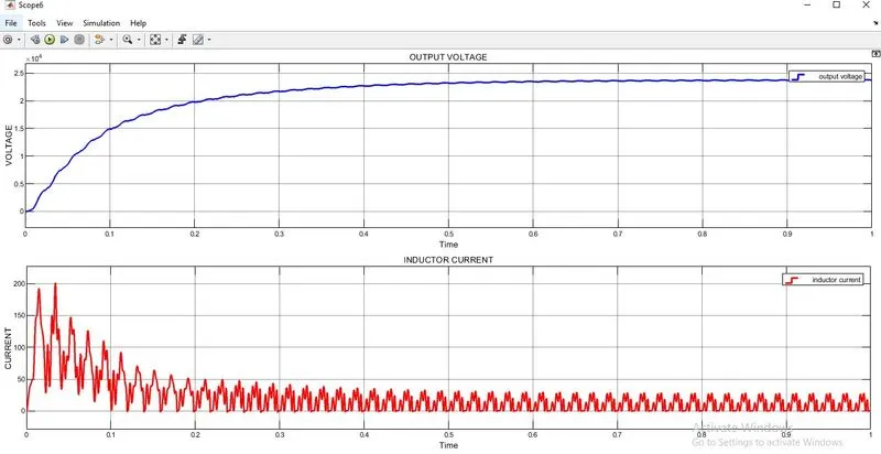
PART B :- high-performance high voltage DC power supply for 15 kV dc output and load in the range of 0-10A
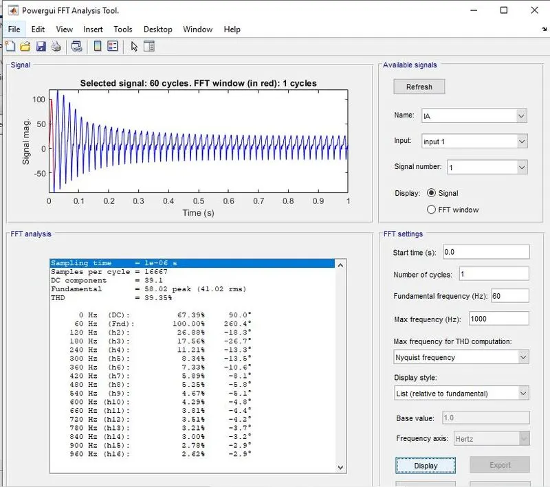
1) THD=39.35% this value is not as per the IEEE standard it should be near about 5% by implementing extra harmonic filters we can also minimize this value
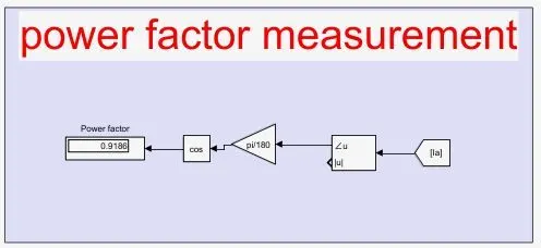
2) power factor = input power factor >0.98 value
3) source voltage and source current
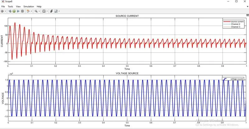
4) output voltage and inductor current-