Project 1
Aim :- The purpose of this project is to simulate an induction motor using the aforementioned parameters, observe the aforementioned test cases using the motor model, and assess the conclusion or result of this simulation.
Block Diagram:
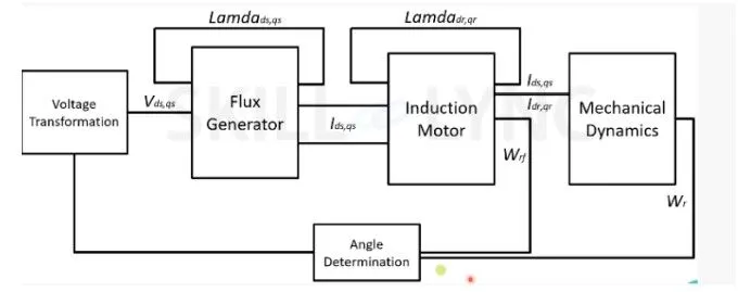
As previously mentioned, I'll be simulating an induction motor in the manner illustrated above, starting with a voltage transformation block that will convert 3-Phase voltage to (dq) voltage supply. In the following block, flux will be created using this dq voltage. Lamdads and Lamdaqs will serve as the flux's stator complements. The motor rotor will then receive the current supplied by the flux generator, which will cause flux to be generated there (Lamdadr and Lamdaqr). All of these will provide dynamics the force and speed to create torque. This provides us with a closed-loop control of the induction motor because the angle of rotation is calculated from the rotor rotation speed and torque.
simulation :-
1) Specification :-
2)Flux generator
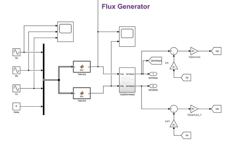
The output of the flux generator subsystem block is Lamdaqs and Lamdads. After subtracting the self magnetizing inductance and rotor current (which are juslt the losses on copper coil). we will have the q axsis and d axsis current respectively.
3)Induction motor
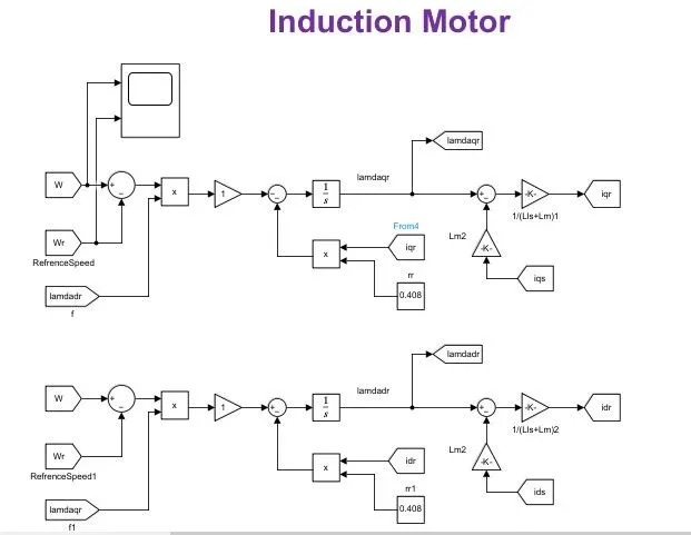
The next part is the induction motor part. The speed is been compared to reference speed and then multiplyed to the rotor flux lincage. Rotor resistance is multilyed by the rotor current to calculate rotor loss by subtraction.
4)Mechanical dynamics
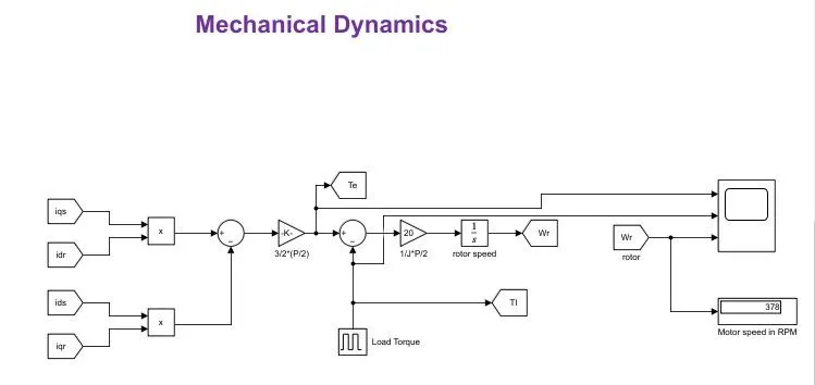
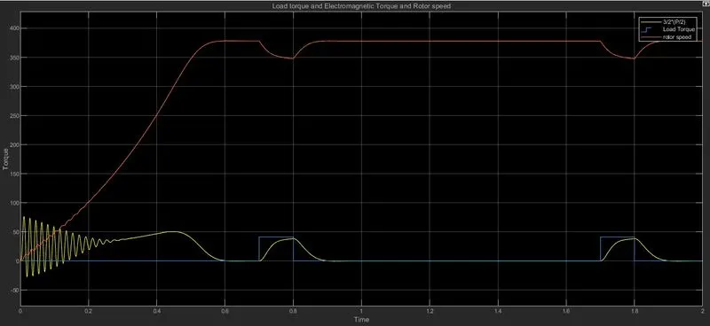
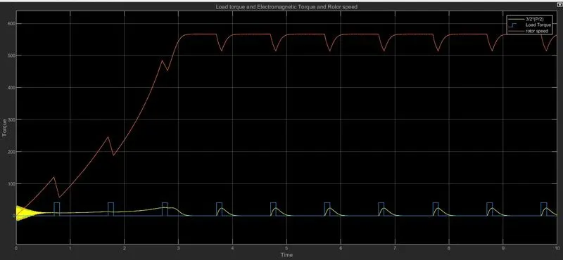
Here, the input current from the stator and rotor is used to calculate the motor torque, also known as electromagnetic torque. For this example, a pulse generator provides the load torque. This means that we will load the motor at specific intervals to observe how it changes the motor torque. The real rotor speed is then calculated by multiplying and integrating this, which is then compared and provided to the induction motor.
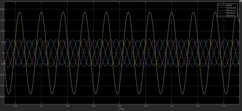
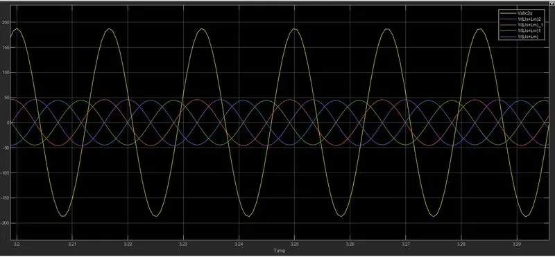
The 3 phase voltage input is given by the three sine waves with the angle thete. Using a buscreator it then given to function block which then transform the three phase votage to dq voltage using the following formulars.
(2/3)*(u(1)*cos(u(4))+u(2)*cos(u(4)-(2*pi/3))+u(3)*cos(u(4)+(2*pi/3)))
(2/3)*(u(1)*sin(u(4))+u(2)*sin(u(4)-(2*pi/3))+u(3)*sin(u(4)+(2*pi/3)))
Given : -
-Motor power. 5 horsepower(3.75kW),
-3-phase 3-wire,
230V, 60Hz, 4-pole
rs=0.531Ω,">rs=0.531Ω, Lls=Llr=2.52mH">Lls=Llr=2.52mH
rf=0.408Ω">rf=0.408Ω Lm=84.7mH
J=0.1kgm2
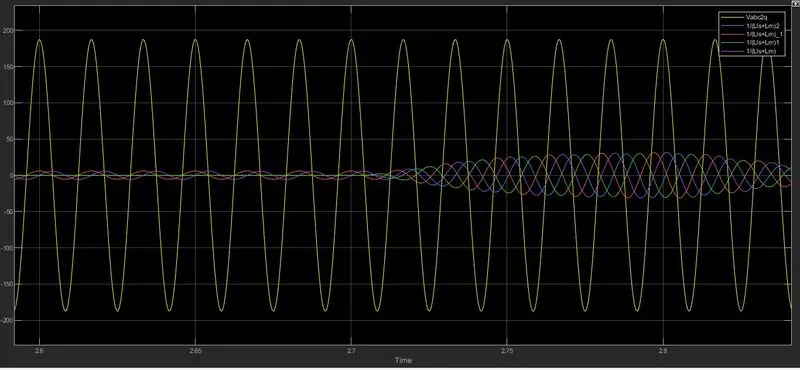
-From the above inputvoltage images we could see that the motor is powered by a 230V 3-phase suply with 60Hz and 120° phase difference.
-Sator resistance is set to 0.531ohms
-Rotor resistance is set to 0.0408ohms
-Stator and Rotor inductance is set to 2.52mH
-Moot mutual inductance is also set as 84.7mH
-Moment of inertia is given as 0.1kgm^2 which is 1Nm^2
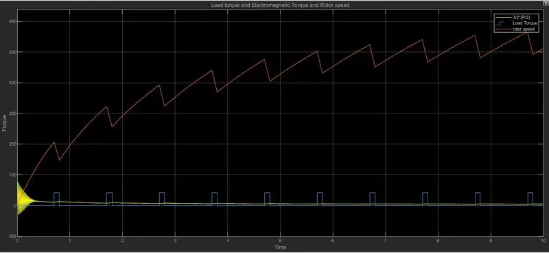
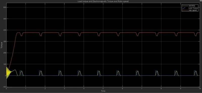
The motor torgue is 50Nm hence aplying a load torgue of 0.83 times motor torgue makes it 41Nm.
Results :-
1) Simulate the start-up behaviour of the induction motor represented in the stationary d-q reference frame. Provide simulation plots of