Study of a Interior Permanent Magnet (IPM) Motor with MAXWELL-2D
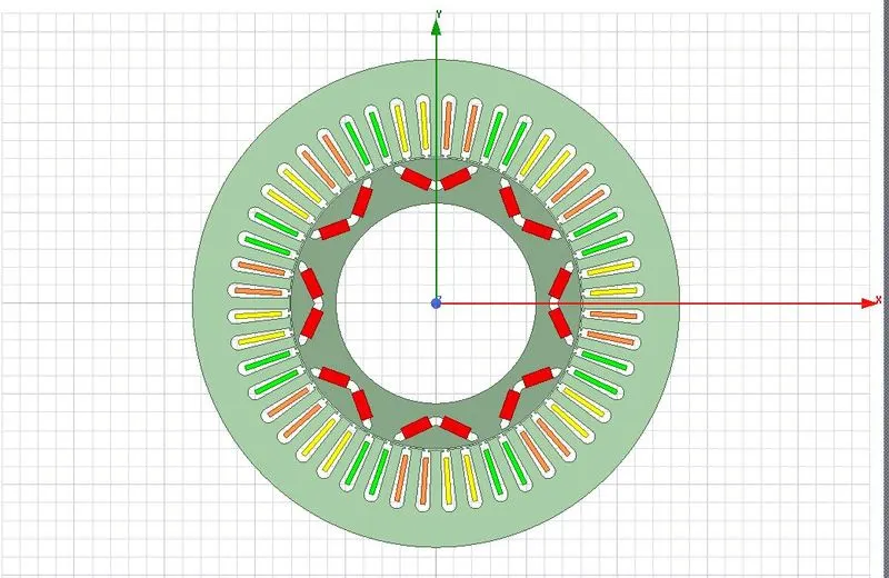
In this discussion, we have designed the Toyota Prius-2004 Interrior Permannet Magnet (IPM) motor. All the design specifications are available in "Study of a Permanent Magnet Motor with MAXWELL 2D Example of the 2004 Prius IPM Motor". It is a 8 pole three phase machine which will rotate at 3000 rpm. The following figure shows the whole-2D Model of the motor in Maxwell platform.
Motor Dimensions (Stator)
Stator outer diameter: 269.24 mm
Stator inner diameter: 161.9 mm
Stack length: 83.82 mm
Number of slots: 48
Slot opening height (Hs0): 1.03 mm
Slot body height (Hs2): 29.5 mm
Slot opening width (Bs0): 1.93 mm
Slot wedge maximum width (Bs1): 5 mm
Slot body bottom width (Bs2): 8 mm
Slot body bottom fillet (Rs): 5 mm
Iron material: M19_29G
Motor Dimension (Rotor)
Rotor Outer Diameter: 160.4 mm
Rotor Inner Diameter: 110.64 mm
Number of poles : 8
Limited diameter of PM ducts (D1): 157.44 mm
Bottom width for separate (O1): 3 mm
Distance from duct bottom to shaft surface (O2): 7.28 mm
Duct thickness (B1): 4.7 mm
Rib width (Rib): 14 mm
Rib height (HRib): 3 mm
Maximum distance between side magnets: 4.5 mm
Magnet thickness: 6.48 mm
Total width of all magnet per pole: 32 mm
Magnet material : N36Z_20
Using the above dimension and maximum current of 250 A, we have three phase current excitation `I_A,I_B,I_C`
`I_A = I_{max}*sin(omega_{rad}t+theta)`
`I_B = I_{max}*sin(omega_{rad}t-((2pi)/3)+theta)`
`I_C = I_{max}*sin(omega_{rad}t+((2pi)/3)+theta)`
These balanced three phase current excitation is given to the Phase A,B and C respectively. The phase A,B and C cointain the coil having 9 number of conductors. Taking time step of `250 mus`and starting from `10 ms`to `15 ms`, we will get the torque waveform like this
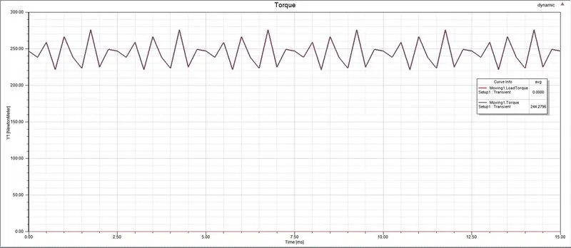
The average value of the torque is 244 N-m. By taking lower step size, we will get the continuous waveform. Here, one can observe that the torque is not steady. It has some ripple. This ripple is due to the flux barrier and the interrior PM design. Therefore we will get a variable torque at constant speed. Hence this can be observe from the Torque VS Speed characteristics.
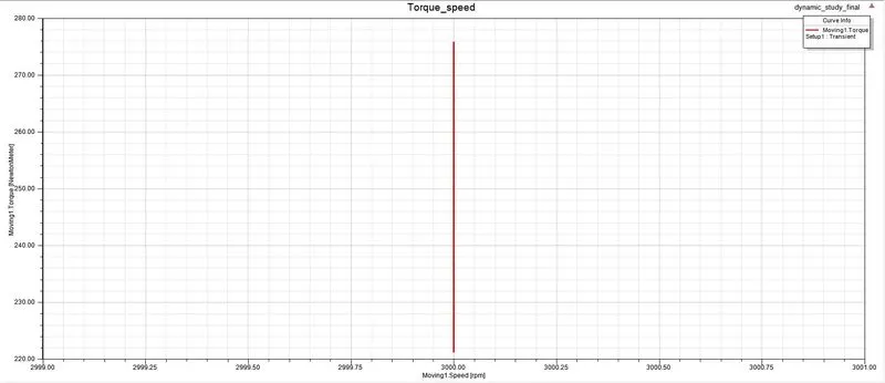
In this way, we can tell that the Prius-2014 IPM motor is a constant speed motor. The range of variation of torque is from 221-276 N-m.
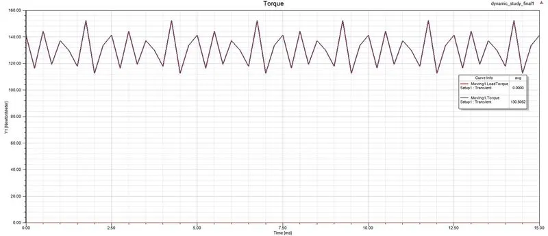
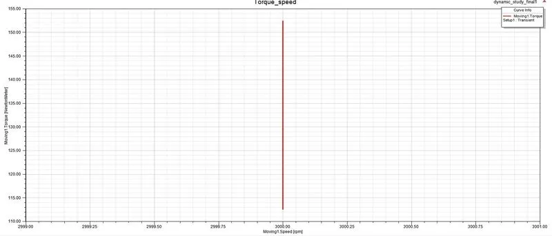
In the second part of this project, we have chnaged the magnet to Ferrite based magnet i.e. Ferrite Y30BH(YBM-2B) and the iron material to M43_29G. The average torque reduces to 130 N-m. The range of variation of torque is also reduced i.e. 112.5-152.5 N-m. There is a slight reduction in flux linkgae from 0.4 Wb to 0.38 Wb. The Torque, Speed torque waveform and flux linkage waveform are shown below
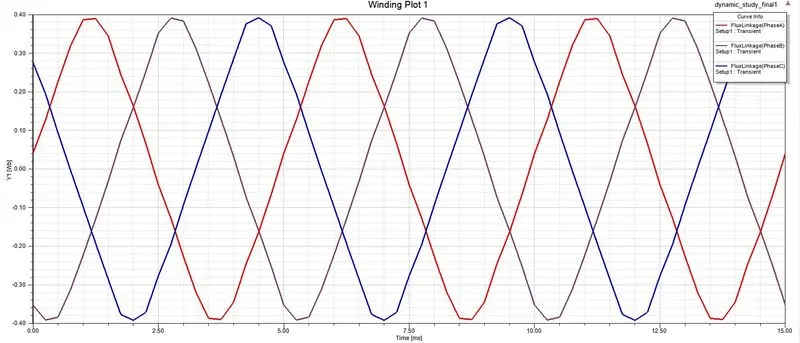
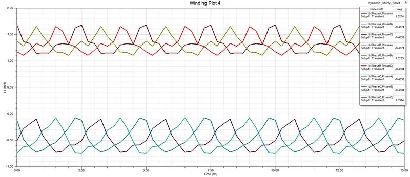
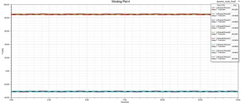
Since the flux linkage in phases change little bit, there is a difference in the self and mutual inductance as well.
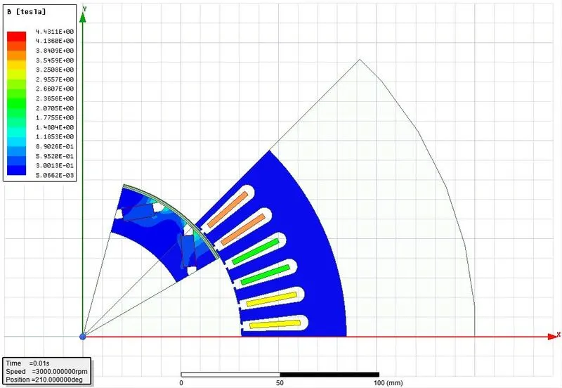
From the magnetic flux density (B) - plot, we observe that the tooth flux density increases in case of the ferrite based IPM magnet.
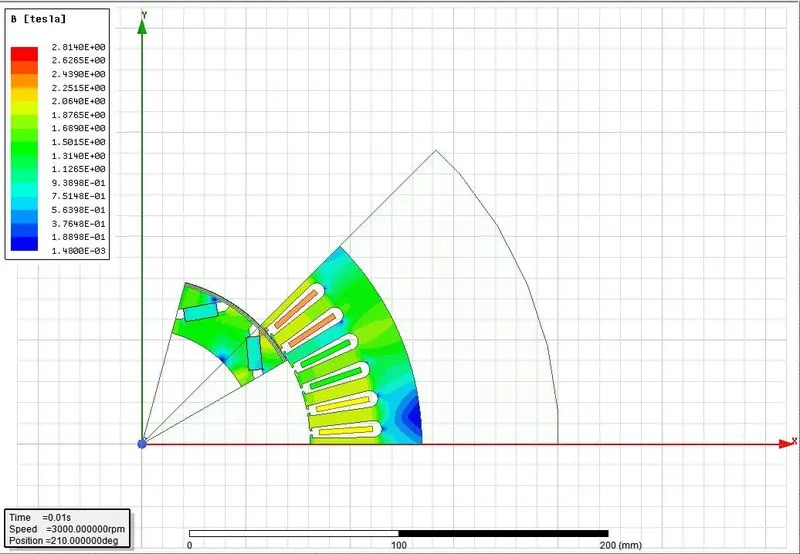
B-plot for the N36Z_20 magnet and M19-29G iron based motor
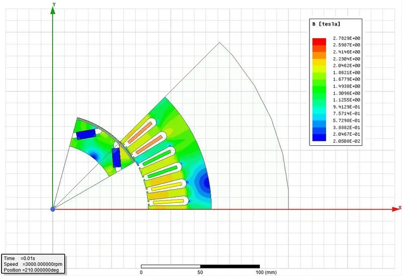
B-plot for the ferrite magnet and M43-29G iron based motor
Therefore using teh M43-29G we are getting equivalent response. To differentiate the things, cast iron is taken instead of M43-29G. The results are shown below
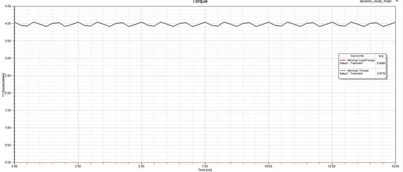
Torque waveform
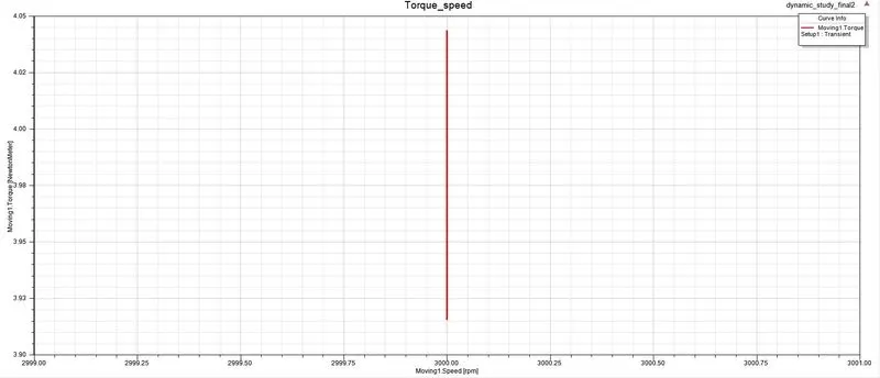
Torque-Speed characteristics
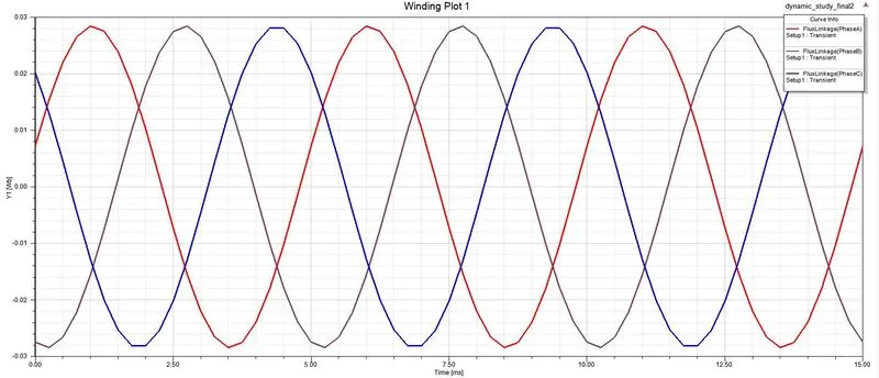
Flux linkage waveform
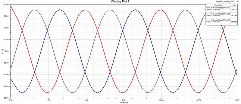
Induced Emf waveform
Inductance waveform
Flux-density Plot
Use of cast iron as stator and rotor material does not hive appriciable results. As seen from the above average toque reduces to 4 N-m, Maximum flux value also decreses to 0.03 Wb. Induced emf is sinusoidal completely. Therefore, stator Iron affects the performance of the machine. In similar way the magnet is responsible for flux and flux density in side the machine.
Note: The attached file named "Prius_07_07_2021" contain all the detailed plot