Simulation of an Induction motor in different frame of references
As the application of induction motor in the industry is huge, it is important to study its steady-state along with the transient behaviour. Various model has been developed for this, and the d-q model or two-axis model has been tested good and proven to be accurate.
Equations that govern the performances of an induction motor are
- 3 phase to two phase conversion
- flux equation
- equivalent circuit equation
- torque euation
- motor equation
The matrix below represents the transformation from three phase to two phase
`[F_{0dq}]=[P_theta][F_{ABC}]`
where, `[F_{0dq}]`is the zero, d and q axis voltages, `[F_{ABC}]`is the three phase votage matrix and `[P_theta]`is the transformation matrix
`[P_theta]=[[0.5,0.5,0.5],[costheta,cos(theta-2pi/3),cos(theta+2pi/3)],[sin theta,sin(theta-2pi/3),sin(theta+2pi/3)]]`
Sufficient flux is generated by the flux generator equations i.e.
`V_{ds}=R_si_{ds}-omega_rlamda_{qs}+Slamda_{ds}`
`V_{qs}=R_si_{qs}+omega_rlamda_{ds}+Slamda_{qs}`
equivalent circuit equation: Based on the equivalent circuit discussed in the lecture, we can write it as
`V_{rd}=0=R_ri_{rd}-omega_{da}lamda_{rq}+S{L_{lr}i_{rd}+L_mi_{sd}+L_mi_{rd}}`
`V_{rq}=0=R_ri_{rq}+omega_{da}lamda_{rd}+S{L_{lr}i_{rq}+L_mi_{sq}+L_mi_{rq}}`
torque equation gives the expression for the electromagnetic torque i.e.
`T_e = 3/2 P/2(lamda_{ds}i_{qs}-lamda_{qs}i_{ds})`
`lamda_{qs}=L_mi_{qr}+(L_{ls}+L_m)i_{qs}`
`lamda_{ds}=L_mi_{dr}+(L_{ls}+L_m)i_{ds}`
Finally, the motor equation gives the relationship between the electrical and mechnical parameter
`T_e-T_l=Jd omega_m/dt`, where `omega_m = 2/P omega_e`
Now, the study is done on different reference frame
- stationary d-q reference frame
- synchronous reference frame
- rotor reference frame
- rotor flux reference frame
In stationary d-q reference frame, `theta=0`, because d-q axis do not rotate in addition to that d-axis is chosen to coincide with the stator phase A axis. Hence, `omega=d theta/dt = 0`
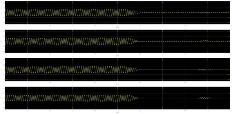
Simulation results of `iqs,ids,iqr,idr` at stationary d,q- axis reference frame
In synchronously rotating reference frame `theta = omega_st`. Here, the d and q-axis are rotating at synchronous speed. Hence, `omega=d theta/dt = omega_s`. Similarly, for rotor reference frame, `omega = omega_r`. Here, d and q-axis are rotating at rotor speed
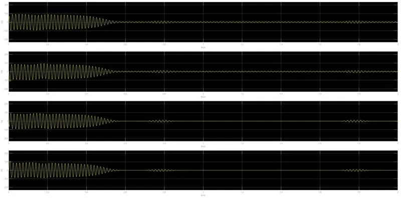
Simulation results of `iqs,ids,iqr,idr` at synchronous reference frame
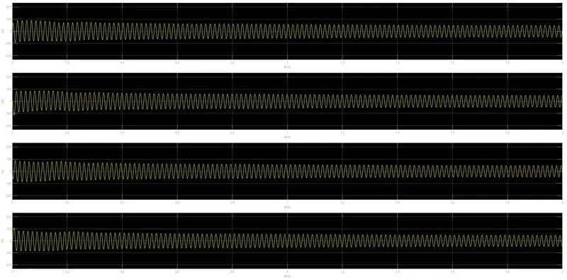
Simulation results of `iqs,ids,iqr,idr` at rotor reference frame
The frequency of the mmf will be `Sf`where,`f`is the supply frequency i.e. 60Hz. slip will be calculated as `(omega_s-omega_r)/omega_s`
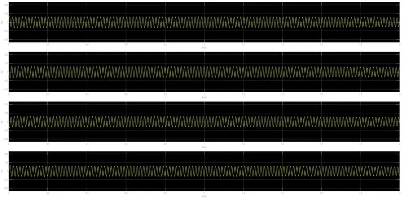
Simulation results of `iqs,ids,iqr,idr` at rotor flux reference frame