The task of this project is to quantify the improvement in fuel economy numbers for the hybrid vehicle (kmpl), compared to the conventional vehicle, on the urban cycle (UDDS) and highway cycle (HWFET). Also, to analyze and understand the vehicle operating points in terms of engine and motor speed, torque, transmission speeds, pedal positions, gear, distance traveled, battery voltage, current, SoC, etc.
1) Load the Project2 folder as the Current Folder in Matlab.
2) Run the “Project2_InitFile.m” Matlab script.
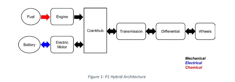
3) Copy the Conventional vehicle Simulink model created for Project 1 in this folder. Figure 1: P1 Hybrid Architecture Hybrid Drives Development
4) Modify this model into a hybrid vehicle model. The lecture presentations can be used as a reference. Battery and Supervisory controller models developed in the assignments can be reused.
5) Add additional ‘To Workspace’ blocks for transferring the desired Simulink vehicle data into the Matlab workspace.
6) Simulate the hybrid model on the desired drive cycles.
a. Tabulate the fuel economy numbers (kmpl) for UDDS and HWFET cycles. Compare these numbers with the baseline numbers for the conventional vehicle model from Project 1.
b. Plot the time trace for the engine, transmission input, transmission output, and wheel speed on one plot.
c. Plot engine torque, power, fuel rate, and consumption using subplots.
d. Plot accelerator and brake pedal, gear command, vehicle desired and actual speed, and vehicle distance using subplots.
e. Plot the engine operating points on the engine fuel map.
f. Plot motor speed, torque, and motor input power using subplots.
g. Plot pack voltage, current, and SoC using subplots.
h. Plot the motor operating points on the motor input power map, with the motor max motoring and generating torque curves.
i. Write down appropriate brief comments on each of these plots, describing the vehicle behavior throughout the drive cycle.
j. Generate the plots for both drive cycles
As discussed in Lecture 11, Project 2 deals with the development of a forward energy-based fuel consumption model of a P1 hybrid vehicle. This model is based on the conventional vehicle model from Project 1.
The main goal of this project is to understand the functionality of a P1 hybrid and be able to model it.
Honda Insight motor and battery are considered for this project. Data is taken from the ADVISOR database developed by NREL, USA. Data is provided in the project files.
“Project2_InitFile.m” is a Matlab script used to load all the variables required for running the Simulink model and for post-processing. The drive cycle selection is also done here. Before running the Simulink vehicle model, run this initialization script.
“Project2_InitFile.m” is a Matlab script consisting of vehicle data, used to load all the variables required for running the Simulink model and for post-processing. The drive cycle selection is also done here. Before running the Simulink vehicle model, this initialization script is run. All the files of vehicle data are loaded to the workspace through this script.
%%%%%%%%%%%%%%%%%%%%%%%%%%%%%%%%%%%%%%%%%%%%%%%%%%%%%%%%%%%%%%%%%%%%%
%% Skill-Lync -> Hybrid Drives Development
% Project 2 - Forward based model of P1 hybrid vehicle
% By - Paleswar sahu
% Description:
%% Initialization File
% Initialization file for loading the variables for the Conventional vehicle simulation model
%% Vehicle Parameters
M = 1500; % Vehicle weight [kg]
Cr = 0.015; % Rolling resistance coefficient
Rw = 0.35; % Rolling radius [m]
Cd = 0.33; % Drag coefficient
Af = 2; % Frontal area [m2]
rhoa = 1.225; % Air density [kg/m3]
Vwind = 0; % Wind velocity [kmph]
g = 9.81; % Gravitational acceleration [m/s2]
theta = 0; % Slope [deg]
myu_road_tire = 1; % Coefficient of friction between tire - road interface
%% Powertrain Parameters
FDR = 3.73; % Final Drive Ratio / Diff Ratio
DiffEff = 0.99; % Differential efficiency (assumed independent of operating conditions)
NumGear = 4; % Number of gears in transmission
TransGear = [1:NumGear]; % Transmission Gears
TransRatio = [3.06, 1.62, 1, 0.7]; % Corresponding Transmission ratios
TransEff = 0.90; % Transmission efficiency (assumed independent of operating conditions)
TC_SR = [0, .5, .6, .7, .8, .87, .92, .94, .96, .97, 1]; % Torque Converter Speed Ratio (Matlab default) -> TurbSpd/PumpSpd
TC_TR = [2.232, 1.5462, 1.4058, 1.2746, 1.1528, 1.0732, 1.0192, 1, 1, 1, 1]; % Torque Converter Torque Ratio (Matlab default) -> TurbTrq/PumpTrq
TC_Cf = 1e-4 * [.72558, .66322, .63463, .59042, .51331, .4144, .29287, .22444, .12186, .04386, 0]; % Torque Converter Capacity Factor (Matlab default) -> PumpTrq/PumpSpd^2 [Nm/rpm^2]
load Vehicle_Data/Engine_data_1_9L_Saturn_95kW
load Vehicle_Data/Trans_Shift_map
load Vehicle_Data/EM_Honda_Insight_10kW
load Vehicle_Data/ESS_NiMH6
ESS_init_soc = 0.8;
ESS_soc_max = 0.9;
ESS_soc_min = 0.6;
%% Driver Parameters
Kp = 10; % P gain for driver PI model
Ki = 1; % I gain for driver PI model
Drive_Cycle_Select = 1; % Drive cycle selection
% Drive cycle values in m/s
if Drive_Cycle_Select == 1
load DriveCycles/UDDS;
elseif Drive_Cycle_Select == 2
load DriveCycles/HWFET;
elseif Drive_Cycle_Select == 3
load DriveCycles/FTP;
elseif Drive_Cycle_Select == 4
load DriveCycles/US06;
elseif Drive_Cycle_Select == 5
load DriveCycles/NEDC;
elseif Drive_Cycle_Select == 6
load DriveCycles/WLTP;
end
time_end = cyc_time(end);
vel_end = cyc_vel(end);
Simulink Blocks:-
The below Simulink blocks are the blocks that are introduced in the Conventional Vehicle Simulink Model to make it a Hybrid Electric Vehicle Model. Also, there are some changes made to the existing blocks to function according to the new blocks and act as a complete Hybrid Drive. The P1 Parallel Hybrid concept is applied to this Hybrid Vehicle.
P1 Parallel Hybrid:-The electric machine is connected directly to the crankshaft of the internal combution engine. P0 and P1 architectures do not allow the mechanical disconnection of the electric machine from the engine. On the other side P2, P3 or P4 configurations disconnects the electric machine from the engine through a clutch.
A hybrid system that is connected directly to the crankshaft of the engine with some type of clutch/fluid coupling between the electric motor and the gearing.This Drivetrain operates on feedback signals. Output Velocity from the Powertrain is fed into the Driver which then generates the Acceleration and Brake. The same Acceleration and Brake are fed into the Controller as input and are used for the rest of the operations.
Controller:-There is a different kinds of Controllers, one is the Supervisory Controller and the others are the Control Units. The input data for the Control Units come from the Supervisory Controller. The supervisory Controller has conditions to follow which directly depend on the Driver's action and based on the same, the control signals are given to the other Control Units.
Engine Control Unit:-In the existing Engine Control Unit for the Conventional Vehicle, there are some changes made to be a Hybrid Drivetrain. New input signals are implemented like 'Eng_on'. The logic behind this is to make the Vehicle more Fuel efficient by turning off the engine whenever it is not required.
Idle Speed Controller:-The same logic is applied here as Engine Control Unit. The idle speed is made to be 0 whenever the Engine is off. The 'Eng_on' input signal is used with the 'Eng_idle_spd' with the product block for the logic to implement.
Transmission Control Unit:-A 'Memory' block is used in the existing Transmission Control Unit for Conventional Vehicle. Memory block outputs the input from the previous time step. The Memory block holds and delays its input by one major integration time step. When placed in an iterator subsystem, it holds and delays its input by one iteration.
Using the 'Throttle' and 'VehicleSpeed' input signals it is controlling the gears. Depending on the vehicle speed ShiftLogic is upshifting and downshifting the gears. At Gear more than or equal to 3rd gear, it gives the 'Clutchlockup' signal to the vehicle.
EM Control Unit:-Engine Machine Control Unit block is operating using the 'EngSpd' signal. By using the Engine Speed, EM Control Unit is giving 'EMTrqReq' which is Engine Machine Torque Requirement. Engine Speed data is used for the maximum and minimum Torque for the EM, which is then decided using the 'Switch' block, where the threshold is the product of the 'EM_Throttle' divided by 100.
Powertrain:-This is a P1 Hybrid Powertrain architecture which has an electric Machine connected parallel to the 'Engine' and both are connected to the 'Crankhub' of the Vehicle. It also has a 'Ess' which is an Energy Storage System or Battery for P1 Hybrid Vehicle.
Engine:-Compare to the Conventional Vehicle everything remains the same, the only thing implemented is the 'Eng_On' 'From' signal from the Supervisory Controller. It operates on the 'EngSpd' and 'EngTrqreq' which is the Engine Torque requirement and gives the 'EngTrq' of the Vehicle.
Engine block uses a similar concept of generating Engine Torque as an Electric Machine, using the input signal 'Engine Speed' with the maximum and minimum torque and passing through the 'Switch' block. Considering 'EngTrqReq' as a threshold value. From the Engine block, 'Eng_Fuel_Rate' and 'Eng_ Fuel_Consumption' can find out. Eng_On signal will make the Engine Fuel Consumption 0 whenever the engine is turned off. As Fuel Consumption is the product of the saturated max Torque and Eng_On signal.
Electric Machine:-Electric Machine which is connected to the crankshaft of the Engine. EM also uses the same method of generating 'EMTrq' which is the Torque of the EM as the Engine generating Engine Torque using a 'Switch' block condition. It also got the input signal as Engine Speed and 'EMTrqReq' which is the threshold value for the Switch condition.
Energy Storage System (ESS):-Energy Storage System or the Battery of the HEV is the storage system of the Electric Machine. It uses the generated Electric Power from the Electric Machine which is then divided with the 'Voltage' (feedback signal from the 'Terminal_Voltage' subsystem) to produce 'Current'.
Energy Storage System determines the 'SOC' (State of Charge) signal of the Vehicle. The state of charge (SOC) of a cell/battery denotes the capacity that is currently available as a function of the rated capacity. The value of the SOC varies between 0% and 100%. If the SOC is 100%, then the cell/battery is said to be fully charged, whereas a SOC of 0% indicates that the cell/battery is completely discharged.
Torque Converter:-Torque Converter is generating the transmission input torque from 'TrubineTrq' and 'CrankTrq', and 'TrubineTrq' is generated from 'TrqRatio' and 'PumpTrq'. It uses the Engine Dynamics which subtracts the PumpTrq from CrankTrq and the product of that is divided by the inertia (Eng_inertia+EM_inertia) to give the PumpSpeed.
To select from Turbine speed and Pump speed, the Switch condition is used where the threshold is Clutchlockup at 0. So if the clutch is close Turbine speed will be considered or vice versa.
%%%%%%%%%%%%%%%%%%%%%%%%%%%%%%%%%%%%%%%%%%%%%%%%%%%%%%%%%%%%%%%%%%%%%
%% Skill-Lync -> Hybrid Drives Development
% Project 2 - Forward based model of P1 Hybrid
% By - Paleswar sahu
% Description:
% The following file is to used with the Initialization file and Simulink
% results for post-processing of the data.
% The file is incomplete, has some examples of how the data is imported
% into a readable format, data analysis and plotting examples.
% Based on the project task, use commands in a similar format as given
% below, to analyse the data and generate required plots.
% You can change variable names if desired
%% Post-Processing File
% File for post-processing the P1 hybrid vehicle simulation model data
%% Renaming variables
Time = out.tout;
Acc_Pdl = out.Acc_Pdl; % Accelerator pedal [%]
Brk_Pdl = out.Brk_Pdl; % Brake pedal [%]
Gear_Cmd = out.Gear_Cmd; % Transmission gear
Trans_In_Spd = out.Trans_In_Spd*30/pi; % Transmission input speed [rpm]
Trans_Out_Spd = out.Trans_Out_Spd*30/pi;% Transmission output speed [rpm]
Eng_Trq = out.Eng_Trq; % Engine brake torque [Nm]
Eng_Spd = out.Eng_Spd*30/pi; % Engine speed [rpm]
Eng_Fuel_Consump = out.Eng_Fuel_Consumption; % Engine fuel consumption [g]
Veh_Dist = out.Veh_Dist/1000; % Distance traveled by vehicle [km]
Veh_Spd = out.Veh_Spd*18/5; % Vehicle speed [kmph]
Wheel_speed = out.Wheel_Spd;
Eng_Fuel_rate = out.Eng_Fuel_rate;
EM_Spd = out.EM_spd*30/pi;
EM_Trq = out.EM_trq;
EM_Power = out.EM_Pwr;
Term_volt = out.term_volt;
SOC = out.soc;
Pack_current = out.pack_crnt;
%% Data Analysis
Eng_Pwr = (Eng_Spd.*pi/30).*(Eng_Trq./1000); % Engine brake power [kW]
rho_petrol = 0.7197; % Density of petrol [kg/L]
kmpl = Veh_Dist(end)/(Eng_Fuel_Consump(end)/1000/rho_petrol); % Fuel economy [kmpl]
% Display Fuel Economy of the Cycle
fprintf('\n fuel economy of drive cycle = %2.2f kmpl ',kmpl)
%% Plotting vehicle characteristics time trace
figure(1)
subplot(3,1,1)
hold on
grid on
plot(Time,Trans_In_Spd, 'linewidth', 1, 'Color', 'black');
ylabel('Speed [rpm]')
xlim([0, Time(end)]);
ylim([0, 6000]);
legend('Trans Input');
subplot(3,1,2)
hold on
grid on
plot(Time, Trans_Out_Spd, 'linewidth', 1, 'Color', 'red');
ylabel('Speed [rpm]')
xlim([0, Time(end)]);
ylim([0, 6000]);
legend('Trans Output');
subplot(3,1,3)
hold on
grid on
plot(Time,Wheel_speed, 'linewidth', 1, 'Color', 'black');
xlim([0, Time(end)]);
xlabel('Time [s]');
ylabel('Wheel speed(m/s)');
legend('wheel speed');
%% plotting engine torque, engine power, fuel rate and fuel consumption using subplots
figure(2)
subplot(4,1,1)
hold on
grid on
plot(Time,Eng_Trq,'linewidth',1,'color','r');
xlim([0, Time(end)]);
xlabel('Time [s]');
ylabel('Engine Torque');
subplot(4,1,2)
hold on
grid on
plot(Time,Eng_Pwr,'linewidth',1,'color','b');
xlim([0, Time(end)]);
xlabel('Time [s]');
ylabel('Engine Power');
subplot(4,1,3)
hold on
grid on
plot(Time,Eng_Fuel_Consump,'linewidth',1,'color','g');
xlim([0, Time(end)]);
xlabel('Time [s]');
ylabel('Engine Fuel consumption');
subplot(4,1,4)
hold on
grid on
plot(Time,Eng_Fuel_rate,'linewidth',1,'color','m');
xlim([0, Time(end)]);
xlabel('Time [s]');
ylabel('Engine Fuel rate');
%% Plot accelerator and brake pedal, gear command, vehicle desired and actual speed,
%% vehicle distance using subplots.
figure(3)
subplot(3,1,1)
hold on
grid on
plot(Time, Acc_Pdl, 'linewidth', 1, 'Color', 'black');
xlabel('Time [s]');
ylabel('Pedal [%]')
xlim([0, Time(end)]);
legend('Accel');
subplot(3,1,2)
hold on
grid on
plot(Time, Brk_Pdl, 'linewidth', 1, 'Color', 'red');
xlabel('Time [s]');
ylabel('Pedal [%]')
xlim([0, Time(end)]);
legend('Brake');
subplot(3,1,3)
hold on
grid on
plot(Time, Gear_Cmd, 'linewidth', 1, 'Color', 'black');
xlim([0, Time(end)]);
xlabel('Time [s]');
ylabel('Gear');
legend('gear cmd');
%vehicle actual and desired speeds and vehicle distance
figure(4)
subplot(3,1,1)
hold on
grid on
plot(Time,Veh_Spd,'linewidth',1,'color','green');
xlim([0, Time(end)]);
xlabel('Time [s]');
ylabel('Vehicle Actual Speed');
subplot(3,1,2)
hold on
grid on
plot(cyc_vel,'linewidth',1,'color','green');
xlim([0, Time(end)]);
xlabel('Time [s]');
ylabel('Vehicle Desired Speed');
subplot(3,1,3)
hold on
grid on
plot(Time,Veh_Dist,'linewidth',1,'color','green');
xlim([0, Time(end)]);
xlabel('Time [s]');
ylabel('Vehicle Distance');
%% Plotting engine operating points on engine fuel map
figure('Name','Engine Operating Points');
hold on
grid on
title('Engine Operating Points','fontsize',12);
p1=plot(Eng_map_spd*30/pi,Eng_max_trq,'linewidth',2,'color','r');
p2=line([Eng_map_spd(end)*30/pi Eng_map_spd(end)*30/pi],[0 Eng_max_trq(end)]);
set(p2,'linewidth',1,'linestyle','--','color','b');
p3=line([Eng_map_spd(1)*30/pi Eng_map_spd(1)*30/pi],[0 Eng_max_trq(1)]);
set(p3,'linewidth',1,'linestyle','--','color','b');
[c,h] = contour(Eng_map_spd'*30/pi,Eng_map_trq,Eng_fuel_map');
clabel(c,h);
xlabel('Engine Speed [rpm]');
ylabel('Engine Torque [Nm]');
title('Engine Fuel Consumption Map [g/s]');
legend([p1 p3],{'Max Curve','Operating Points'});
axis([Eng_map_spd(1)*30/pi Eng_map_spd(end)*30/pi 0 Eng_map_trq(end)]);
% Plot motor speed, torque, motor input power using subplots.
figure(6)
subplot(3,1,1)
hold on
grid on
plot(Time,EM_Spd,'linewidth',1,'color','r');
xlim([0, Time(end)]);
xlabel('Time [s]');
ylabel('Motor Speed [rpm]');
subplot(3,1,2)
hold on
grid on
plot(Time,EM_Trq,'linewidth',1,'color','b');
xlim([0, Time(end)]);
xlabel('Time [s]');
ylabel('Motor Torque [Nm]');
subplot(3,1,3)
hold on
grid on
plot(Time,EM_Power,'linewidth',1,'color','g');
xlim([0,Time(end)]);
ylim([-1000,5000]);
xlabel('Time [s]');
ylabel('Motor Input Power [W]');
% Plot pack voltage, current and SoC using subplots.
figure(7)
subplot(3,1,1)
hold on
grid on
plot(Time,Term_volt,'linewidth',1,'color','r');
xlim([0, Time(end)]);
xlabel('Time [s]');
ylabel('Terminal voltage[v]');
subplot(3,1,2)
hold on
grid on
plot(Time,SOC,'linewidth',1,'color','b');
xlim([0, Time(end)]);
xlabel('Time [s]');
ylabel('SOC[%]');
subplot(3,1,3)
hold on
grid on
plot(Time,Pack_current,'linewidth',1,'color','g');
xlim([0, Time(end)]);
xlabel('Time [s]');
ylabel('Pack Current[W]');
%Plot the motor operating points on the motor input power map, with the motor max motoring and generating torque curves.
figure('Name','Motor operating Points');
hold on
grid on
title('Motor Operating Points','fontsize',12);
p1=plot(EM_map_spd*30/pi,EM_max_trq,'linewidth',2,'color','r');
p4=plot(EM_map_spd*30/pi,EM_max_gen_trq,'linewidth',2,'color','g');
p2=line([EM_map_spd(end)*30/pi EM_map_spd(end)*30/pi],[EM_max_gen_trq(end) EM_max_trq(end)]);
set(p2,'linewidth',1,'linestyle','--','color','b');
p3=line([EM_map_spd(1)*30/pi EM_map_spd(1)*30/pi],[EM_max_gen_trq(1) EM_max_trq(1)]);
set(p3,'linewidth',1,'linestyle','--','color','b');
[c,h] = contour(EM_map_spd'*30/pi,EM_map_trq,EM_inpwr_map');
clabel(c,h);
xlabel('Motor Speed [rpm]');
ylabel('Motor Torque [Nm]');
title('Motor Input power Map [g/s]');
legend([p1 p3 p4],{'Max Curve','Operating Points','regeneration'});
axis([EM_map_spd(1)*30/pi EM_map_spd(end)*30/pi EM_max_gen_trq(1) EM_map_trq(end)]);
%end
Zeroth order equivalent circuit model:-
%0th order equivalent circuit model
%clear all
%close all
%clc
load("ESS_NiMH6.mat");
load("Pack_Current_test.mat");
pack_current = I_pack;
ESS_init_soc = 1;
nominal_voltage = 7.7;
Volt_batt = 154;
soc = out.soc;
term_volt = out.term_volt;
%Terminal_voltage = term_volt.Data(:,1);
pack_crnt = out.pack_crnt;
time = out.tout;
Int_res = out.Int_res;
%Int_res = (Volt_batt-term_volt)/pack_crnt;
%plotting of current,voltages,soc,internal resistance
figure(1)
subplot(4,1,1)
hold on
grid on
plot(time,pack_crnt);
xlabel('time');
ylabel('pack current');
subplot(4,1,2)
hold on
grid on
plot(time,term_volt);
xlabel('time');
ylabel('Term volt');
subplot(4,1,3)
hold on
grid on
plot(time,soc);
xlabel('time');
ylabel('SOC');
subplot(4,1,4)
hold on
grid on
plot(time,Int_res);
xlabel('time');
ylabel('Internal resistance');
%calculating the average charging and discharging efficiency of the battery
%Discharging Efficiency
Dis_current = pack_crnt(pack_crnt>0);
Dis_vol = term_volt(pack_crnt>0);
Dis_eff = ((Dis_vol.*Dis_current)./(Volt_batt*Dis_current)).*100;
%charging Efficiency
chg_current = pack_crnt(pack_crnt<0);
chg_vol = term_volt(pack_crnt<0);
chg_eff = ((Volt_batt.*chg_current)./(chg_vol.*chg_current)).*100;
%END OF PROGRAM
Fuel Economy (kmpl):-
Drive Cycle UDDS
The EPA Urban Dynamometer Driving Schedule (UDDS) is commonly called the "LA4" or "the city test" and represents city driving conditions. It is used for light-duty vehicle testing. The UN/ECE Regulation 53 refers to the EPA UDDS as the "Test Equivalent to the Type 1 Test (verifying emissions after a cold start)."
Fuel economy is 14.2044 [kmpl] (Project 1)
Fuel economy is 26.4945 [kmpl] (Project 2)
For Project 2, the value of the Fuel economy which is a P1 Hybrid Electric Vehicle is much better than that of the Conventional Vehicle fuel economy from Project 1.
Drive Cycle HWFET
The Highway Fuel Economy Driving Schedule (HWFET) represents highway driving conditions under 60 mph.
Fuel economy is 16.5010 [kmpl] (Project 1)
Fuel economy is 36.9793 [kmpl] (Project 2)
In the Highway case also the fuel economy of the Project 2 is better than that of Project 1.
As per the Drive Cycles, in the city condition, the fuel economy is not as great/much as in the highway condition. This is the same in both Project 1 and Project 2. This is because generally in the city condition due to more traffic, waiting time for the vehicle increases, and also, starting and stopping the vehicle repeatedly due to traffic consumes more fuel. Gives more fuel consumption and also increases the fuel rate resulting in less fuel economy than that highways.