Project 2
Route the Wiring harness on Given car body and Prepare flatten view drawing in CATIA V5. Application of all Packaging rules, Industry best practices studied in this course shall be demonstrated in design. Apply Protection coverings as required.
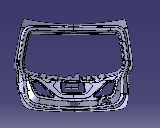
A wiring harness (also called a cable harness or wire loom) is an organized set of electrical wires, connectors, terminals, and protective sheathing that transmits electrical power and signals between different components in a system. It is widely used in automobiles, aerospace, industrial machinery, and consumer electronics to ensure a safe and efficient electrical connection.
Components of a Wiring Harness
Wires and Cables: Conductors for power and signal transmission.
Connectors: Interface points for attaching different components.
Terminals: End connectors to establish electrical contact.
Protective Sheathing: Covers like PVC, braided sleeves, or corrugated tubing to protect against heat, abrasion, and moisture.
Grommets & Clips: Provide mechanical support and strain relief.
Fuse & Relays: For circuit protection and control.
Wiring harness routing refers to the process of designing and arranging the path of wires within a system to ensure:
Optimal performance (minimizing signal interference and power loss)
Mechanical protection (avoiding damage from heat, vibration, or sharp edges)
Space efficiency (avoiding clutter in compact areas)
Ease of assembly & maintenance (clear pathways for troubleshooting)
Wiring Harness Routing Steps :
Create or Download all the Connector or related CAD models from TE Connectivity.
Define the parts as Electrical defined and as electrically connector with Bundle connection as well in Electrical workbench.
Attach all the parts on their respective location using different compass tools .
Proceed with Multibranch routing with required slack and bending radius which is 1.4-1.5 times of diameter.
By using Protective Covering , Cover the wiring and leave some extremity at the connection or connector side for easy movement of wires near connectors in Electrical Harness Assembly.
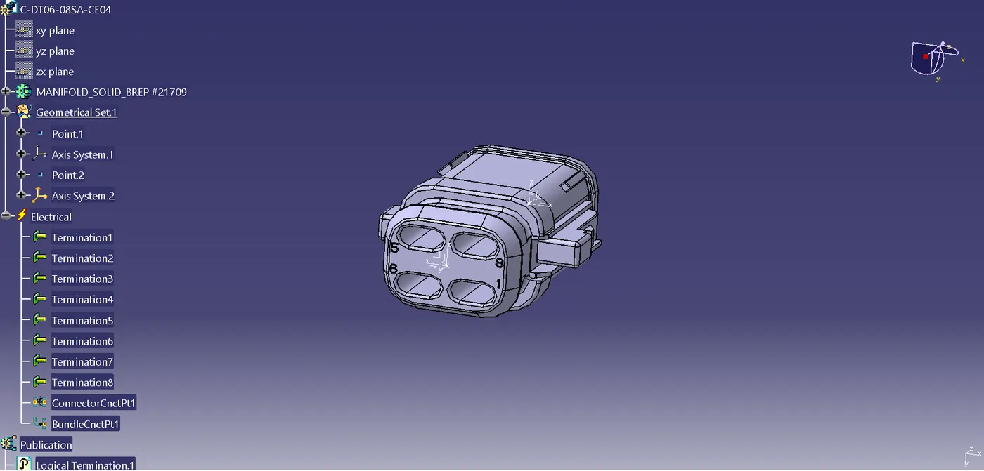
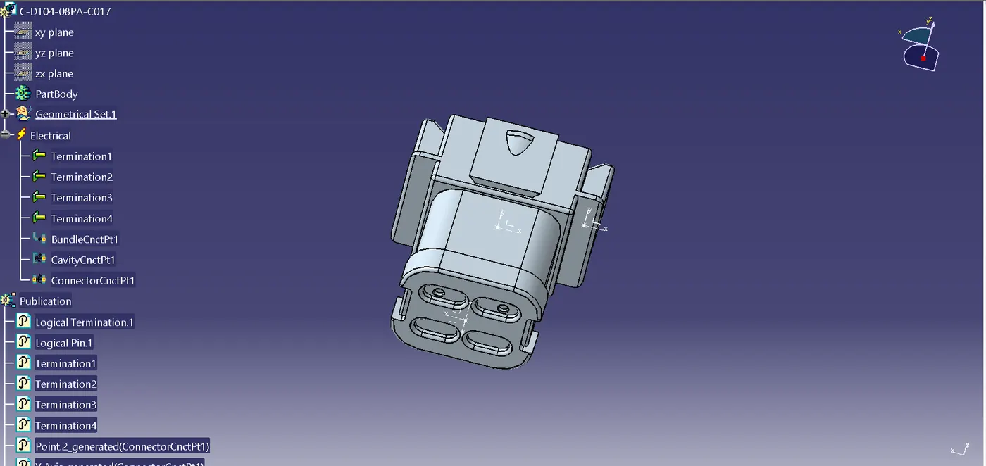
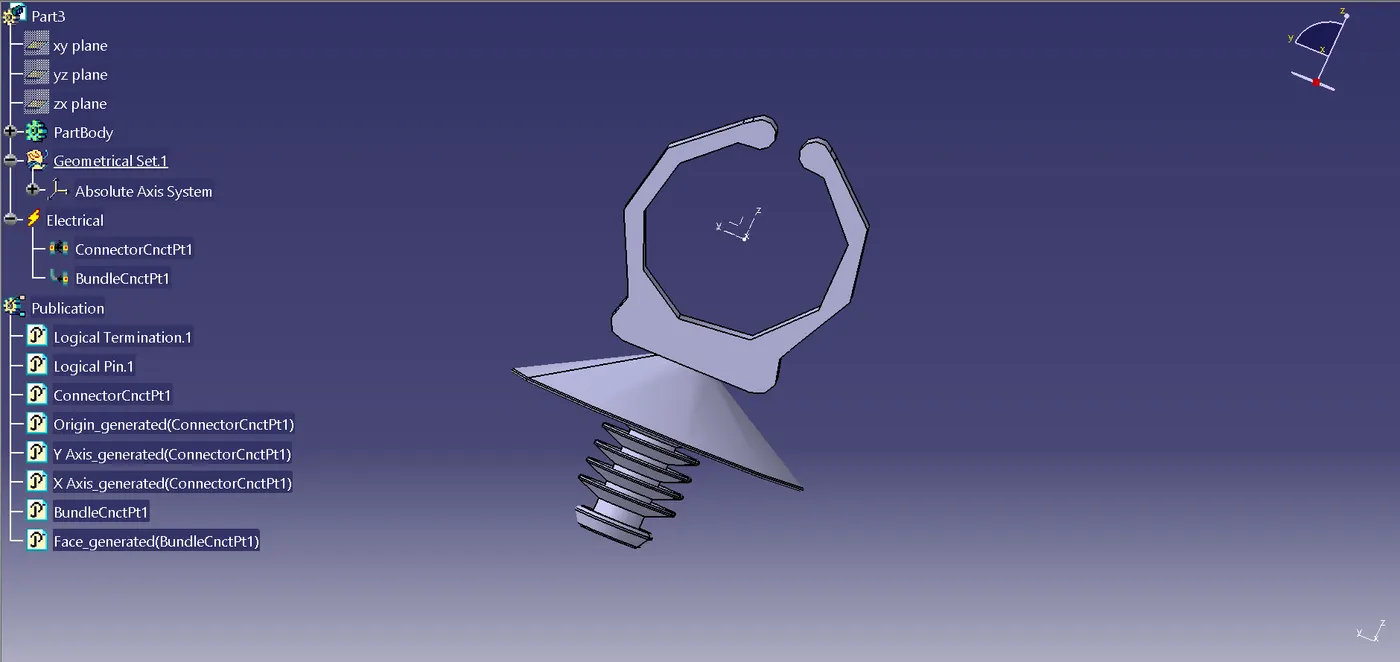
The connectors used are below :
C-DT06-08SA
C-DT04-08PA
FIR TREE CLIP
Steps for defining the connector electrically :
Create a mid point using point definition command tool.
Create an axis on the origin point in such way that y - axis should face towards mating side.
Define the part as connector and the define the connector connection point.
Define the Bundle Connection Point on the face representation.
We've to perform same steps on each connector to define them electrically. If the connector or part is not defined then the electrical wiring harness won't take palce.
Installing the connectors at the respective location :
For locating the connector on the panel one can use Manipulative tool, Smart Move Tool and the compass tree for the easy movement of parts on the panel.
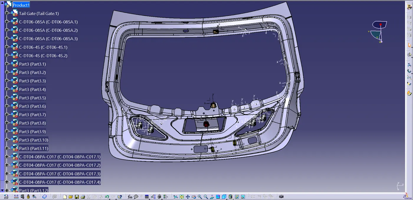
In the above image its visible that the Fir tree clip is attached at the side panel so that the other parts won't get affected at the installation.
The main Purpose of routing is that the it should be effectively organized with minimum space and also without disturbing other parts.
In rear door there are many trims covering the door so to provide a fitment for trim is also to be taken care during routing.
one can use P clamp and other clips/clamps as well but it might take external space on the panel.
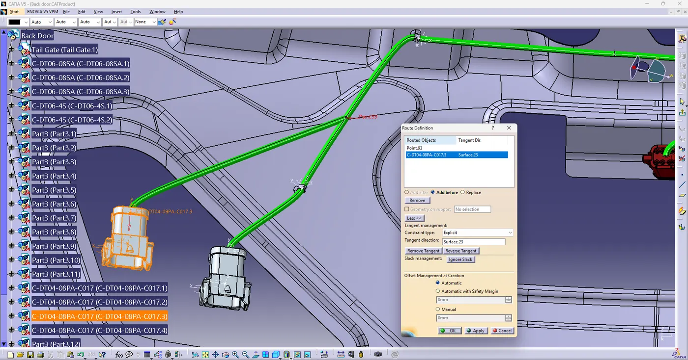
Here the wiring routing is done using the multi branchable tool , as it can be seen harness is done through the fir tree clip.
for the wiring harness perfection one can create an extra point so that the wiring should takes place before or after the Start end connection.
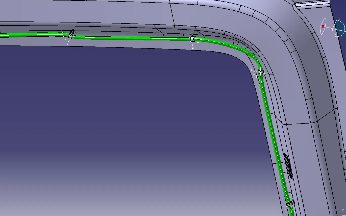
Protection Covering of all the Branches
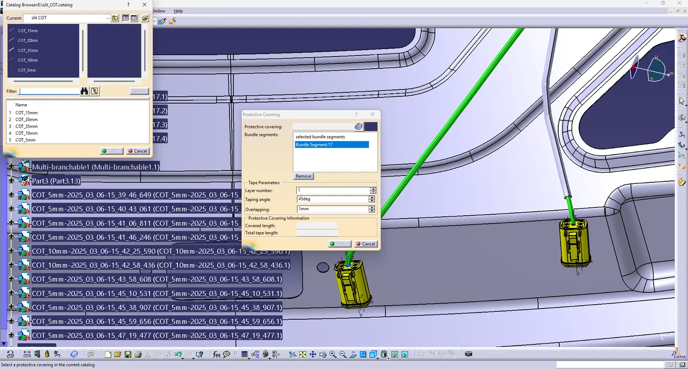
Already a catalogue of Tubes is Created , from there Protection covering can be done as per the required size.
Here 5 mm protection covering is done because the Wiring Diameter size was of 3 mm.
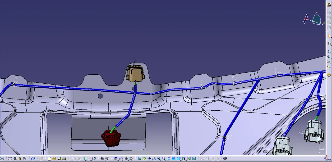
An extremity of approx. 20mm is given for the easy movement of connector and fittings.
Blue Color Representing the Protective Covering on the wirings.
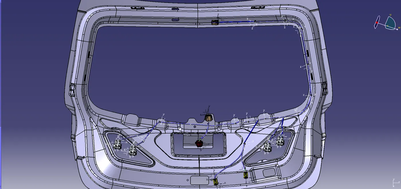
Bundle Continuity Checking :
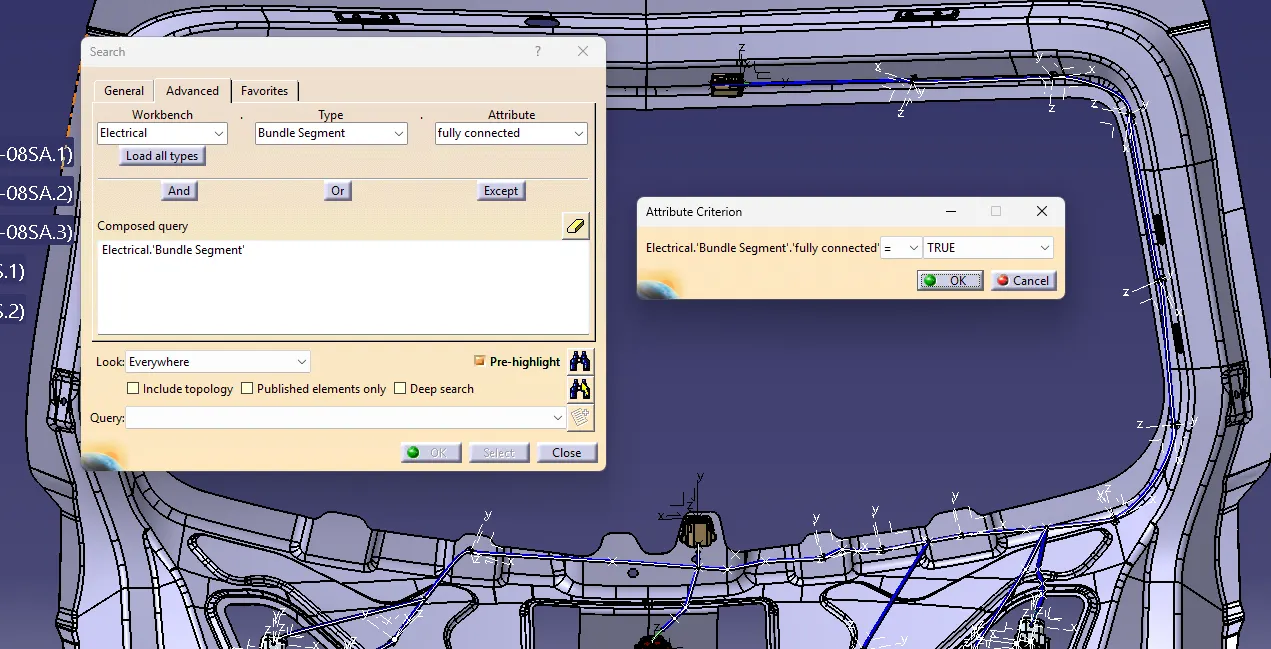
Bundle continuity is checked whether the Bundle connections are electrically connected or not using search command by providing attributes as true if fully connected.
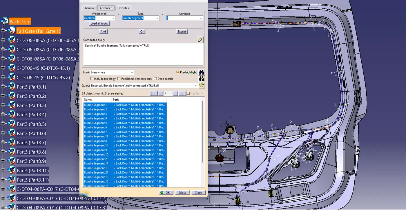
The Bundle connections which are fully connected will be shown in the dialogue box.
Electrical Harness Flattening :
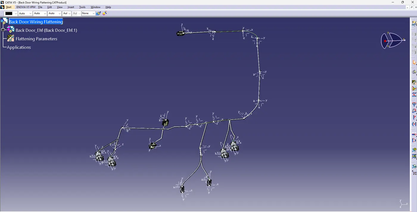
The wiring Harness is flattened for the conversion of 3D into 2D Diagram or Drawing.
Flattening Parameters have been inserted for the representation of lines in 3D and 2D.
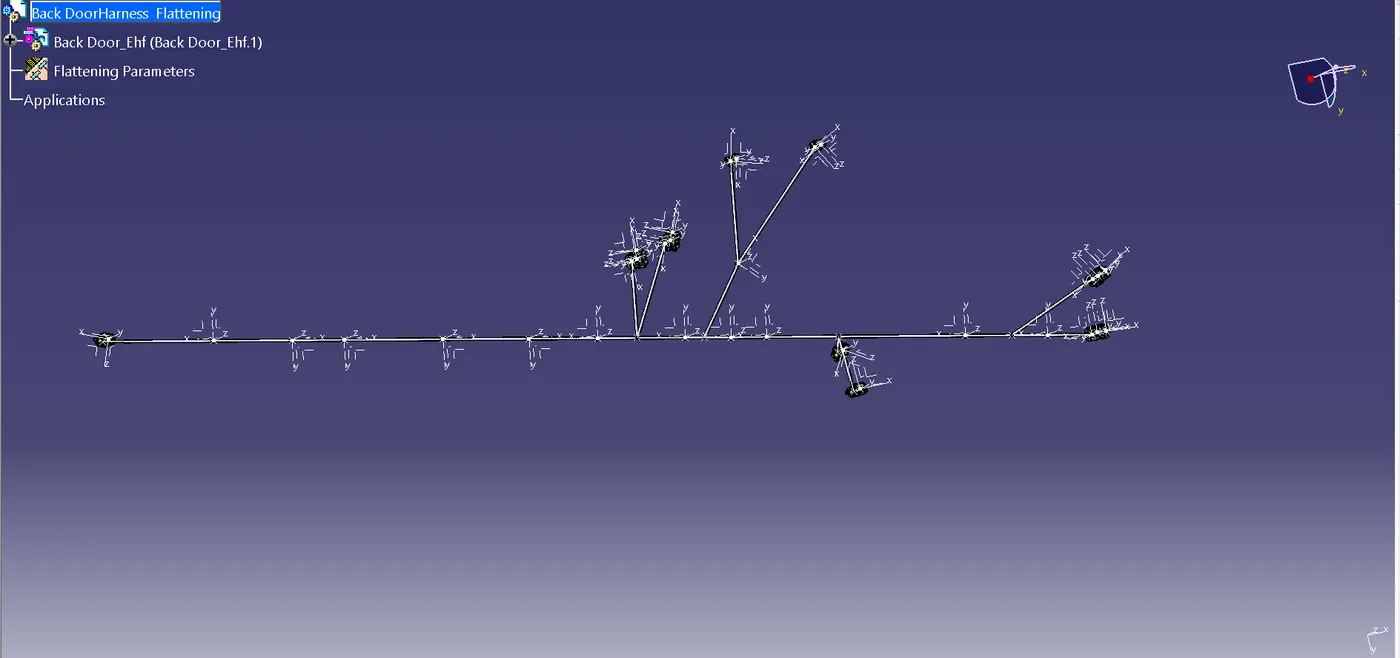
Converting Flattened Harness into sheet Diagram.
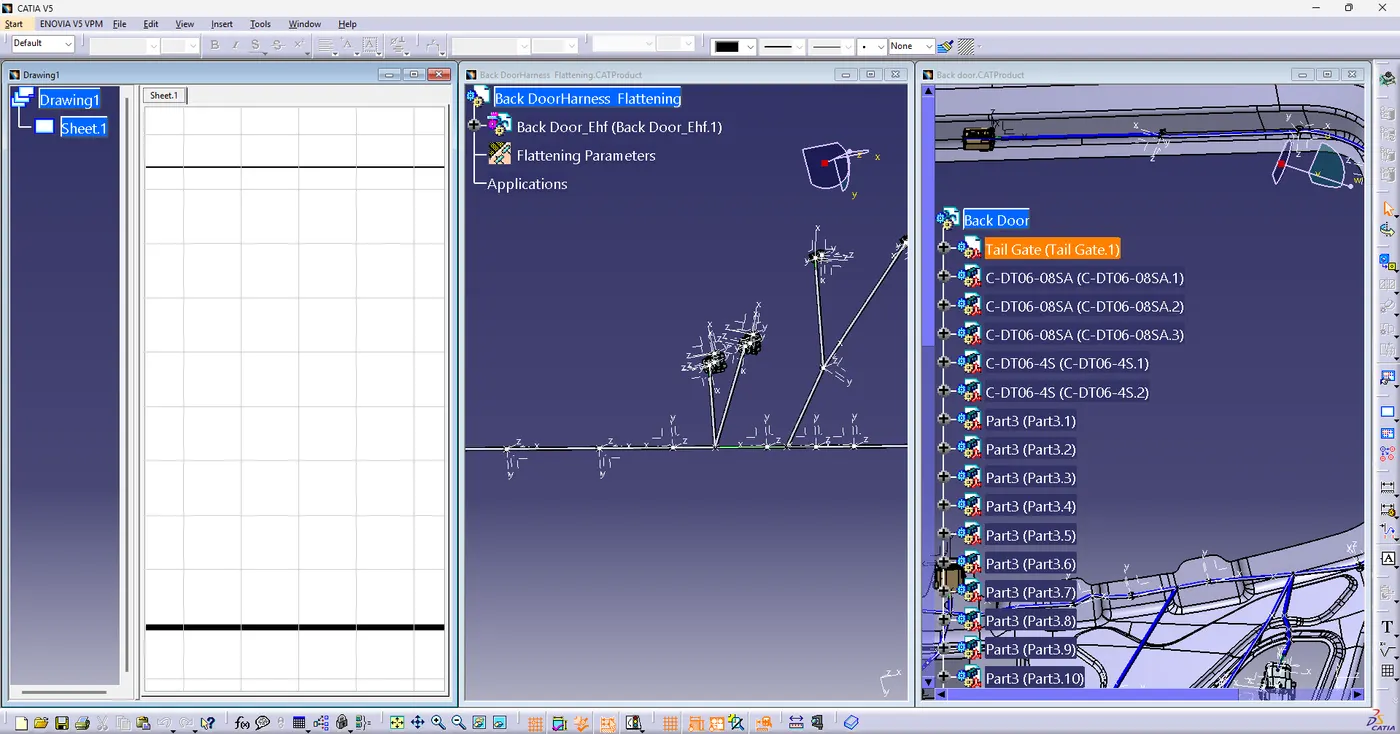
By using Front view and extract command Flattened wiring is inserted into the sheet Diagram.
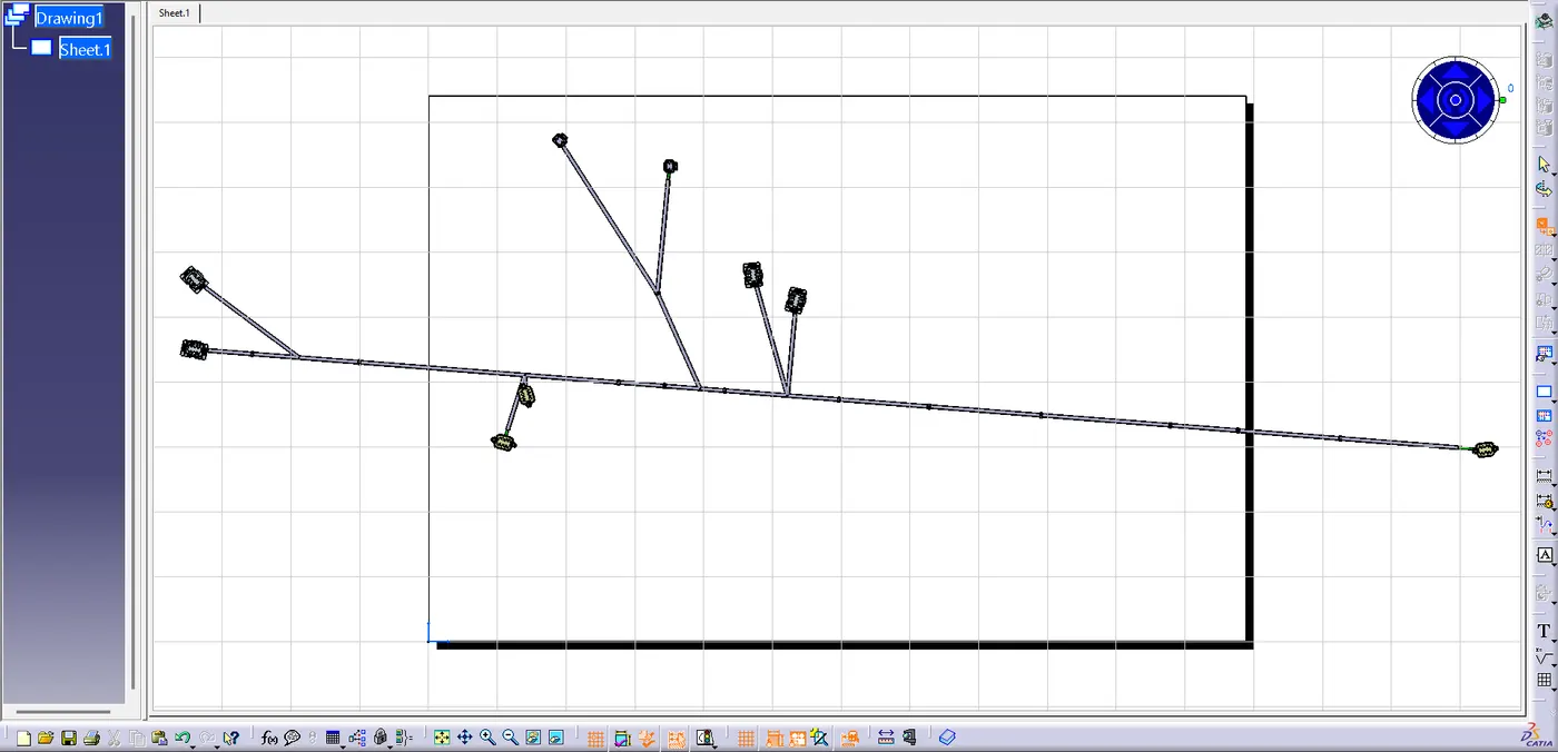
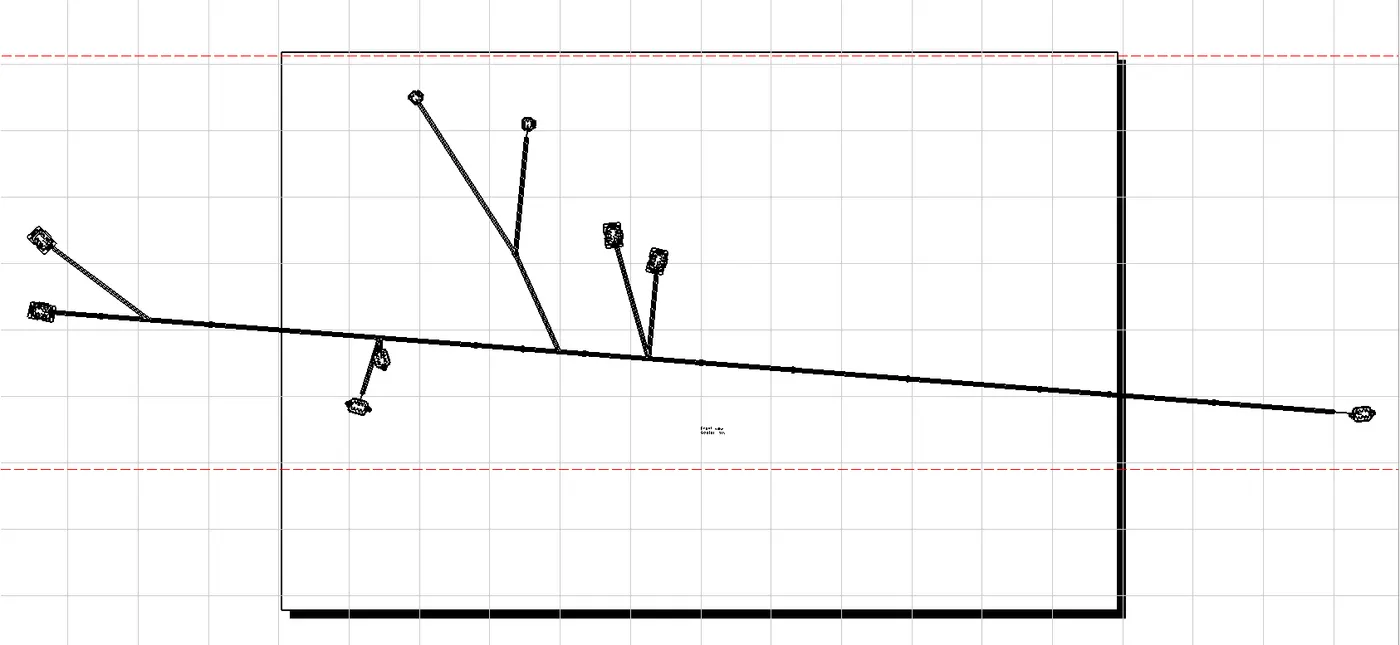
Here Double represents the Protection covering and the single line represents the Bundle Connection.
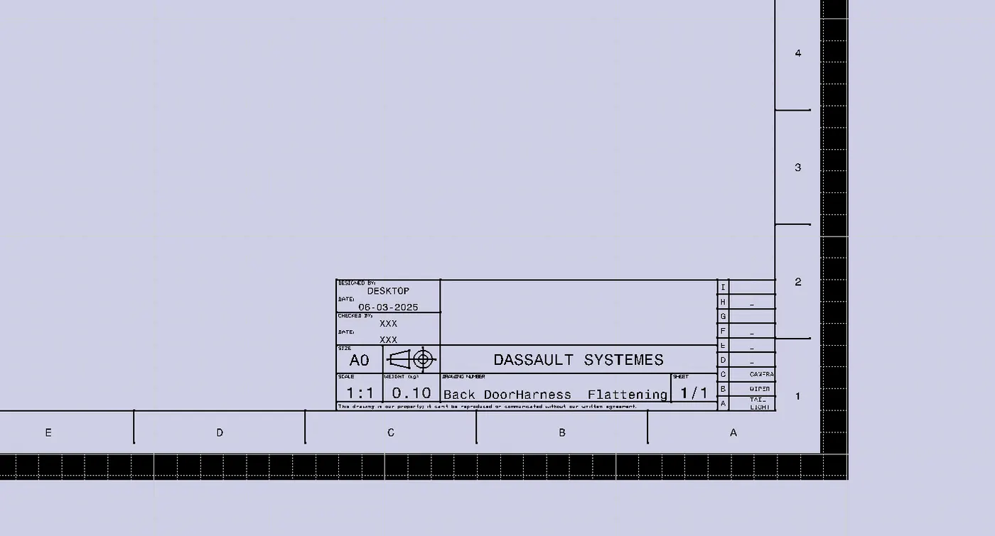
Conclusion :
All required electrical connections have been accounted for, ensuring reliable power and signal transmission throughout the tailgate assembly.
Connectors and routing clips are strategically positioned to minimize potential interference and ease the installation process.
Protective coverings, such as corrugated tubes or braided sleeves, have been specified to safeguard the harness from abrasion and environmental factors.
The flattened layout includes clearly labeled wire segments, connector callouts, and dimensional information for efficient manufacturing and assembly.
All relevant design and safety standards have been followed, ensuring both regulatory compliance and reliable performance.
Final validation checks—such as continuity testing is been done.