Project 2
Que1) Using MATLAB/simulink and the drive cycle from the attached excel sheet, find-
- The max heat generation of the battery
- The SOC of the battery at 2 *104second of the battery operation
| Time | Time Step | Battery Current |
| 00:00.4 | 0.1 | -0.9632 |
| 00:00.5 | 0.2 | -0.952 |
| 00:00.6 | 0.3 | -0.9072 |
| 00:00.7 | 0.4 | -0.9632 |
| 00:00.8 | 0.5 | -1.0304 |
| 00:00.9 | 0.6 | -0.9632 |
| 00:01.0 | 0.7 | -1.0304 |
| 00:01.1 | 0.8 | -1.008 |
| 00:01.2 | 0.9 | -0.9856 |
| 00:01.3 | 1 | -0.9632 |
| 00:01.4 | 1.1 | -0.9184 |
| 00:01.5 | 1.2 | -0.9296 |
| 00:01.6 | 1.3 | -0.9296 |
| 00:01.7 | 1.4 | -0.9296 |
| 00:01.8 | 1.5 | -0.9184 |
| 00:01.9 | 1.6 | -0.9408 |
| 00:02.0 | 1.7 | -0.896 |
| 00:02.1 | 1.8 | -0.9072 |
| 00:02.2 | 1.9 | -0.9072 |
| 00:02.3 | 2 | -0.9408 |
| 00:02.4 | 2.1 | -0.9296 |
| 00:02.5 | 2.2 | -0.9296 |
| 00:02.6 | 2.3 | -0.9968 |
| 00:02.7 | 2.4 | -0.9968 |
| 00:02.8 | 2.5 | -0.9408 |
| 00:02.9 | 2.6 | -0.9408 |
Consider the battery resistance is 0.5 mOhm, delta time is 0.1 and entropic factor is 2
Ans:
Objective: This project aims to analyze battery performance using MATLAB/Simulink based on a given drive cycle data. The focus is on determining two key parameters:
- Maximum Heat Generation: Calculating the maximum heat generated by the battery during its operation.
- State of Charge (SOC) at 2 × 10^4 Seconds: Determining the SOC of the battery at a specific time during its operation.
These insights into thermal behavior and energy usage are valuable for battery management and optimization in various applications.
Given Data :
Battery resistance = 0.5 milli ohm
Entropic heat = 2 X Joules heat
Max current = -0.896
Calculations:
Joule heat = I^2RT
where,
I = Current
R = Battery resistance
T = Time (s)
1) The maximum heat generation in the battery pack
The maximum current in the drive cycle is -0.896 at 2 minutes(120 seconds)
maximum joule heat generated =I^2Rt
=(-0.896^2)*0.5*120
=48.169 milli Joule
Maximum heat generated = Joule heat + Entropic heat
= 48.169 + 2(48.169)
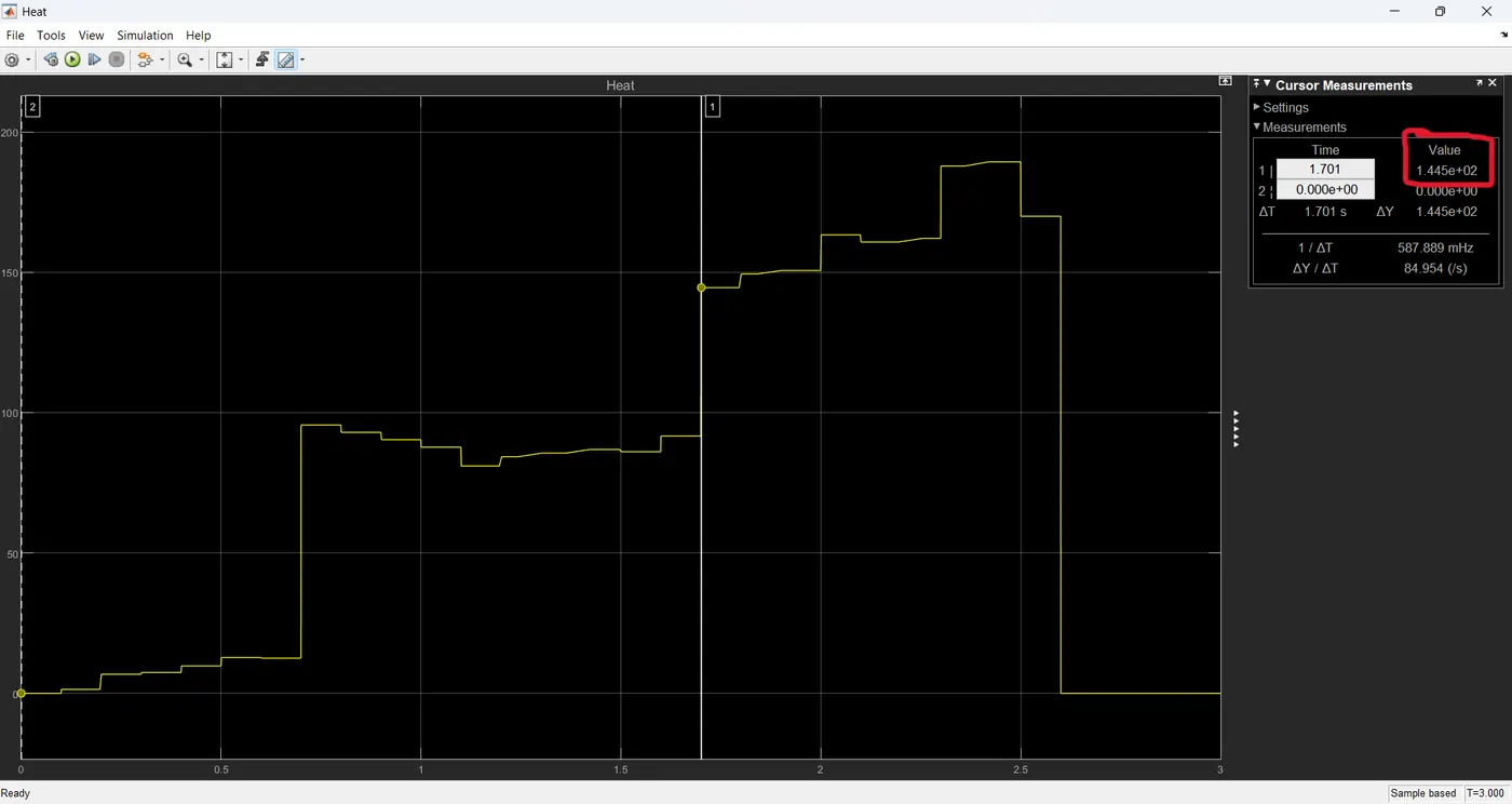
= 144.507 milli Joule
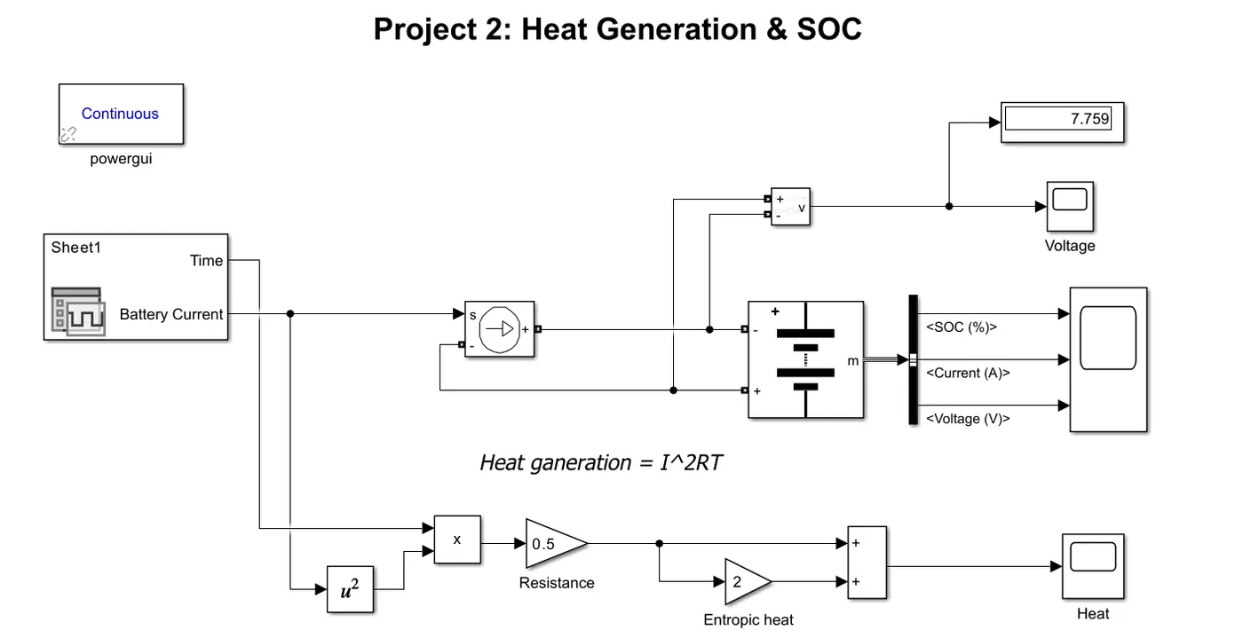
Block Used:
1) Battery
2) Voltage Measurement
3) Controlled Current Source
4) Bus Selector
5) Scope
6) Display
7) Powergui
8) Constant Block
9) Gain Block
10) Product Block
Model:
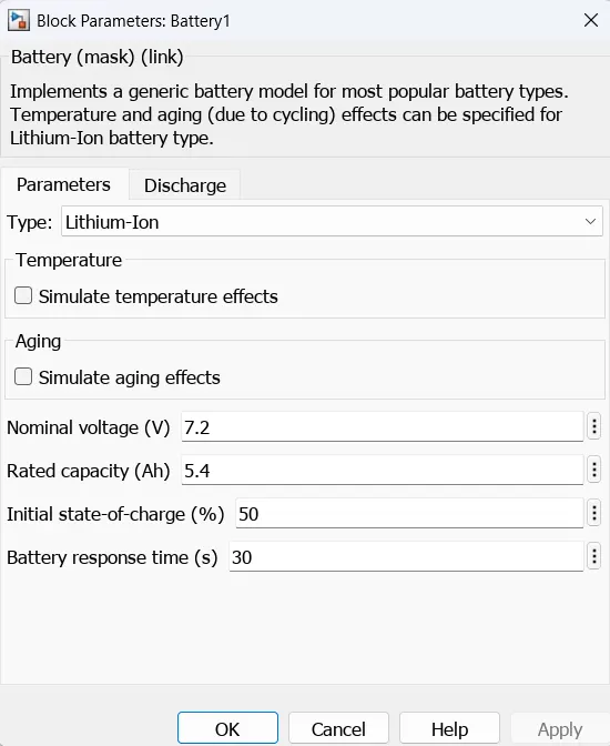
Battery specification:
Steps and Methodology:
Data Import and Preprocessing:
- Import the drive cycle data (time, time step, and battery current) from the provided Excel sheet into MATLAB.
- Ensure the data is consistent and interpolated for the required time intervals.
Simulink Model Design:
- Battery Pack Subsystem:
- Model a battery pack in Simulink using built-in blocks.
- Define internal resistance, capacity, and initial SOC.
- Controlled Current Source:
- Use the drive cycle data to create a controlled current signal.
- Feed this signal as the load to the battery pack.
- Voltage and SOC Measurement:
- Connect a voltage measurement block across the battery pack.
- Configure a scope to monitor SOC over time.
- Battery Pack Subsystem:
Heat Generation Calculation:
- Implement a subsystem to calculate heat generation using H = I^2RT
- Monitor and record the heat generation values during simulation to identify the maximum value.
Simulation Results:
1) The maximum heat generation of the battery:
The Max heat generated in which the current flows in and out i.e., charge and discharge due to internal resistance and chemical reaction during charging and discharging of the battery the heat is generated of 144.507 milli Joule.
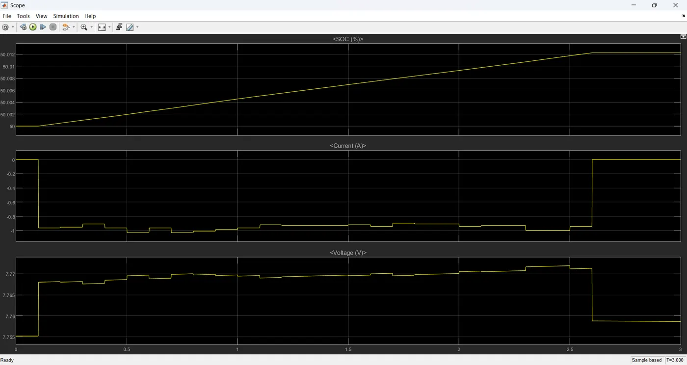
2) The SOC of the battery at 2 *104second of the battery operation
The battery charging is done till 129 seconds after that no current is passed through the battery, so the SOC of the battery is constant from 129 seconds to 208 seconds.
Conclusion: This project successfully demonstrates the use of MATLAB/Simulink to analyze battery performance under a specific drive cycle. The insights gained, including maximum heat generation and SOC at a specific time, are critical for effective battery management and optimization in real-world applications.