Project 2
The Cad provided is a IGS file without any history. Remaster the Solid using best practice as per below :
1 – The Complete design should be parametric and by changing any dimension the complete Part should get updated.
2 – Use Best Practices as Explained
3 – Use Part Design work Bench.
4 – Use minimum number of Command for making the part.
The Cad provided is a IGS file without any history. Remaster the Solid using best practice as per below :
1 – The Complete design should be parametric and by changing any dimension the complete Part should get updated.
2 – Use Best Practices as Explained
3 – Use Part Design work Bench.
4 – Use minimum number of Command for making the part.
8 D – Problem Solving
- For a program launched in June 2020 we are facing a issue , the H Point of the Seat is not as per the OEM given value . The issue is observed in 56 car Seat set out of total production of 3250 cars.
- The issue is observed in Foam. The Foam Hardness is not as per Specs.
- Use 5 M, Pugh, and other technical logical reasoning ways to solve the issue.
1 – A seat need to be designed for which track peel out strength need to be calculated. The hand calculation need to be done for which following details are provided :
H – Point : X – 1175.4 mm , Y – 337.5 mm , Z – 390 mm
Weight of the seat : - 18 Kg
CG – same as H – Point
Alpha Angle : 3 Degree
Beta Angle : 3.7 Degree
Mounting Point :
Point 1 :
X - 1093 mm
Y – 290 mm
Z – 298 mm
Point 2 :
X - 1169 mm
Y – 390 mm
Z – 307 mm
Calculate the strength of the Track (Peel Out Strength) required.
Making of seat back:
In this case we've got provided with dump solid of seat back and head rest so we'll have to creatte sto then we'll have to create the solid foam so for that i extracted the surfaces of the dump solid and repair some dameges over the surfaces then i've created sto.
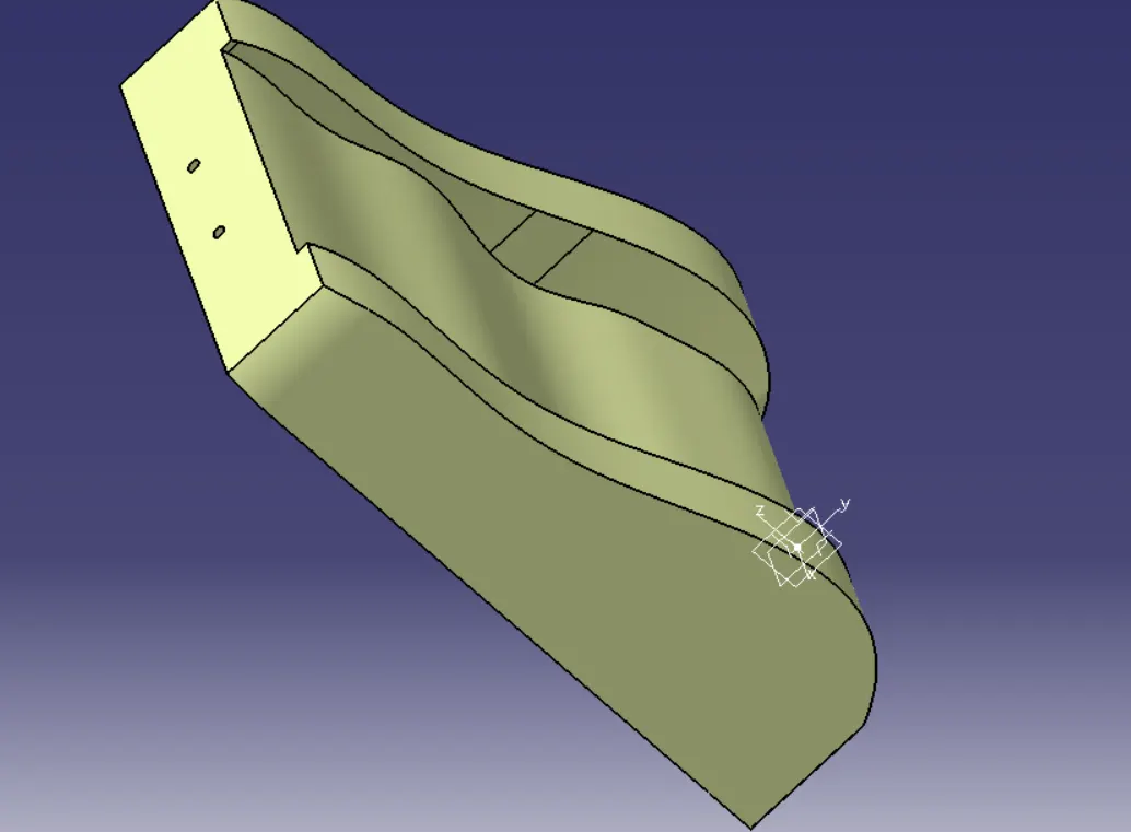
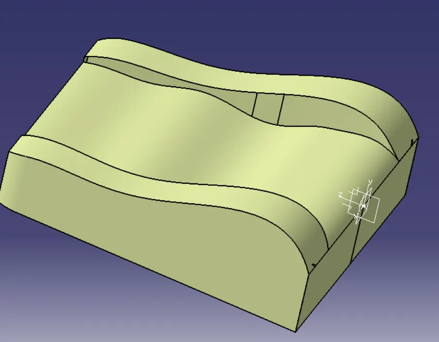
And now we've got a proper sto with no gaps
Then i created intersections of back surface while am i sketching i created projection of the intersection then i offsetted down wards 5mm then same thing i did with the all other planes
Making of wings:
So in this case i've followed a different type of approach which contrast to other apporach which shown in video, So, what am i done is I've extracted the surfaces of wings
Then i begin to create the top and bottom surfaces first i extracted the top surface then took a boundry and extrapolated then i trimmed them together and the same thing I've done for the bottom surface as well.
Making of seat lower part:
Then whatever methods i followed for create seat upper part same thing i applied for the seat lower part as well
STO:
Surface body:
Solid foam:
Making a solid foam from Unproper sto:
Given data:
Then i created proper seat trim outline
And the same procedure we followed for the seat upper and lower applied on this part as well but i tried another different approach in this case as well
As we seen before i took intersections between sto and planes which i created and then i created the sketch and offseted the line of cushion surface by 5mm
Now we've got proper surface body