Project 2
Project 2
BACK DOOR WIRING HARNESS
Statement of assignment:
Route the Wiring harness on Given car body and Prepare flatten view drawing in CATIA V5. Application of all Packaging rules, Industry best practices studied in this course shall be demonstrated in design. Apply Protection coverings as required.
Available connector 3D data can be used, or you can download the connectors from www.te.com
Prepare & Submit all necessary reports like clearance, Clipping/Clamping selection, Harness fixing requirements, Harness continuity, Assumptions if any along with CATIA 3D data.
->> ELECTRICALLY DEFINED CONNECTORS AND CLIPS
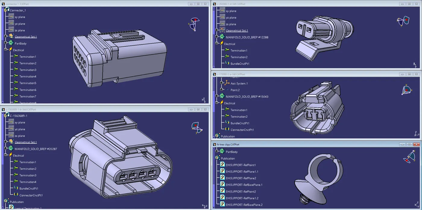
Open the neutral data file (step file or igs file) for the connections in the CATIA component workbench after downloading it from the provided source (TE connectivity website).
Determine the bundle connection point, connector connection point faces, and connector sides that lock mechanically.
By choosing the appropriate edges, create the geometries such as the center points of the connector connection point and bundle connection point.
Then, create an axis on the connector connection point by pointing the X axis to the side of the locking mechanism and the Y axis towards the direction of the connector connection point (mating point). The compatible mating part should also follow the same axis direction.
After obtaining it from the specified source (TE connectivity website), open the neutral data file (step file or igs file) for the connections in the CATIA component workbench.
Find the connector sides that lock mechanically, the bundle connection point, and the connector connection point faces.
Create the geometries, such as the connector connection point and bundle connection point center points, by selecting the right edges. Next, make an axis on the connector connection point by orienting the Y axis in the direction of the connector connection point (mating point) and the X axis to the side of the locking mechanism.
The axis direction of the compatible mating part should likewise be followed.
--> Wiring harness design and Routing
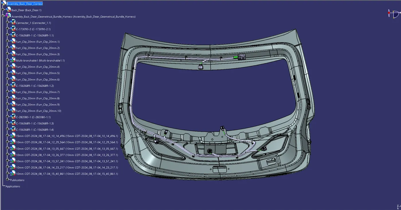
A separate product file for geometrical bundle assembly is added beneath the primary product file for the wiring harness assembly context.
To add all the necessary connectors, fir tree clips, and other items for the harness assembly routing, open the geometrical bundle assembly in a new window, then move to the mechanical assembly workbench.
Using the different instructions available in the mechanical assembly workbench, position the connectors and other components to the desired spot.
To convert the geometrical bundle assembly file into an electrical assembly file, go to the electrical harness assembly workbench, activate the geometrical bundle command, and pick the geometrical bundle assembly file from the tree structure.
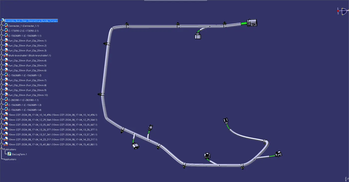
To get the proper bundle connection between connectors, use the multi-branchable document command in the electrical harness assembly workbench to adjust the available options, such as connector diameter, bend radius ratio, build mode, and with the aid of routing objects, define the routing by adding the desired electrically defined components and adjusting the tangency if necessary.
Whenever possible, multi-branch routing should be used while assembling the wiring harness.
By double-clicking the multi-branch-able command, we may add new branches or split the current branches. The wiring harness installation workbench will then immediately transition to and we can add a branch point to the existing bundle at the desired location from there.
To create sub-branches in the assembly, once more navigate to the multi branch-able document command and pick the relevant electrically defined components and bundles.
--> FLATTENING
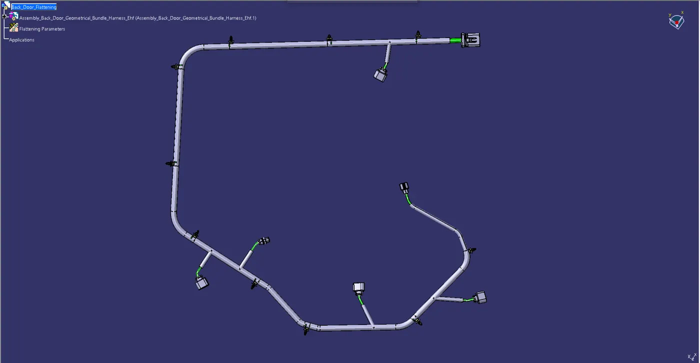
Go to the electrical harness flattening workbench and open a new product file for the wiring harness flattening procedure.
The basic settings, such as the algorithm as coarse, the angle mode as regular, the minimum angle between two branches, the flattening orientation, the flattening scaling, the synchronization, the link, and the drawing choices, appear when you select the harness flattening parameters command.
Check that the wiring harness assembly's components are completely electrically defined and that the bundle continuity is there by opening the input file for the wire harness geometrical bundle product in a new window.
To import the input file into the new product file, pick the geometrical bundle product tree structure using the extract command. The other window will automatically close. Switch to the new product file for the wire harness flattening and set the window as Tile vertically.
When a file is successfully imported into the electrical harness flattening workbench, it will automatically have the suffix.ehf file.
Using the flatten command, we can flatten all of the bundles in the assembly by choosing the appropriate plane. We can then use the various commands available in the electrical harness flattening workbench to adjust the position, angles, etc. as needed. Finally, we can save all of the files in one folder to ensure proper and seamless operations.
To obtain the right perspective, adjust the position, angles, etc. using the several commands available in the electrical harness flattening workbench and cover the bundles with protective coverings.
-->> 2D DRAWING
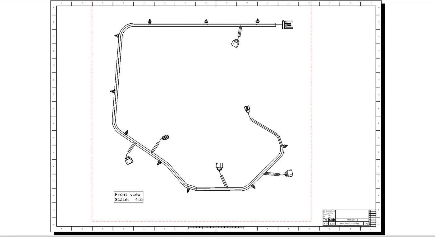
Using the file toolbar, select new and type has drawing to open a new drawing file. In the pop-up box, select the standard, paper size, view type, and other initial options.
By choosing the front view command and the suitable flatten surface from the electrical harness flattening workbench, we can add the front view of the flattened wiring harness assembly to the drawing workbench.
Select the properties and view option by right-clicking on the design sheet's border. From there, enable the 3D wireframe and mark it as always visible using the dress-up feature.
In order to activate the three-dimensional views of the connector, we first navigate to the electrical flattening workbench. Then, by double clicking, we can modify the flattening parameters from the tree structure to project the device's graphic in three dimensions and add a new front view to the drawing.
Using the toolbar insert, drawing, frame and title block, we can also add a frame and a title block to the drawing.
By modifying the dress-up features, a new design file was created that included the front view of the flattened wiring harness assembly and was completely descriptive in relation to the 3D model.