Project 2
project 2::
aim:
to develop a eletric hybrid vehicle by using the UDDS and HWFET drive cycle.
introduction:
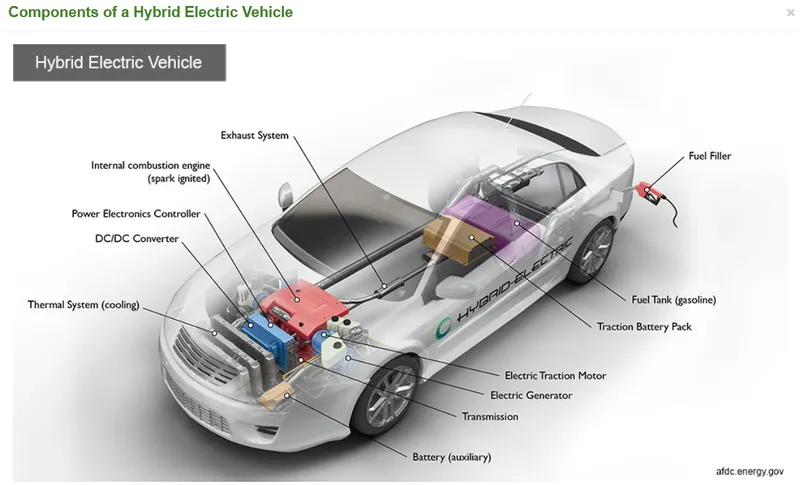
hybrid electric vehicle:
Hybrid electric vehicles are powered by an internal combustion engine and one or more electric motors, which uses energy stored in batteries. A hybrid electric vehicle cannot be plugged in to charge the battery. Instead, the battery is charged through regenerative braking and by the internal combustion engine. The extra power provided by the electric motor can potentially allow for a smaller engine. The battery can also power auxiliary loads and reduce engine idling when stopped. Together, these features result in better fuel economy without sacrificing performance.
Key Components of a HHybrid Electric Car
Task:
The task of this project is to quantify the improvement in fuel economy numbers for the hybrid vehicle (kmpl), compared to the conventional vehicle, on the urban cycle (UDDS) and highway cycle (HWFET). Also, to analyze and understand the vehicle operating points in terms of engine and motor speed, torque, transmission speeds, pedal positions, gear, distance traveled, battery voltage, current, SoC etc.
To do that, the following steps need to be followed:
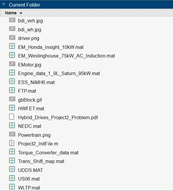
1) Load the Project2 folder as the Current Folder in Matlab.
first of all download the file in which is attached in the question.
it constant of a zip file. we have to open the zip file and copy all the file folder file images etc.
then create a new folder and paste all the files individually.
and now open the matlab and upload the project file like shown in the below figure.
2) Run the “Project2_InitFile.m” Matlab script.
now open the project2_intifile.mat in the new script of the matlab.
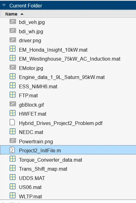
then run the matlab program.
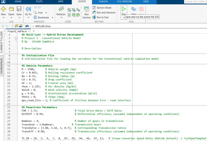
by running the matlab program. the required data are stored in the workspace like this:
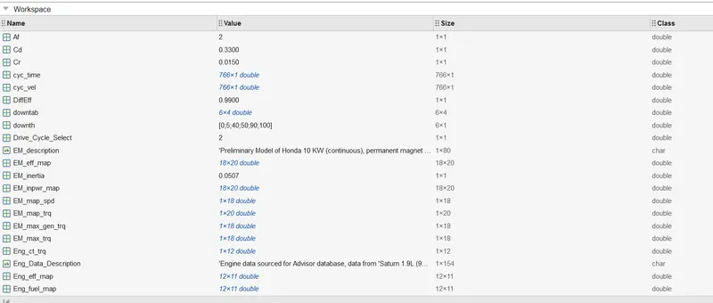
here the project2 required data are available in the workspace with the help of this we can create a simulink model and run that model via this data.
3.3) Copy the Conventional vehicle Simulink model created for Project 1 in this folder. Figure 1: P1 Hybrid ArchitectureHybrid Drives Development.
this is the conventional vehicle simulink model created in the project 1.
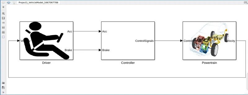
4) Modify this model into a hybrid vehicle model. The lecture presentations can be used as reference. Battery and Supervisory controller models developed in the assignments can be reused.
now modify the conventional electric vehicle to the hybrid electric drive by adding a electric motor.
this isshown step by step:
this is the driver model :
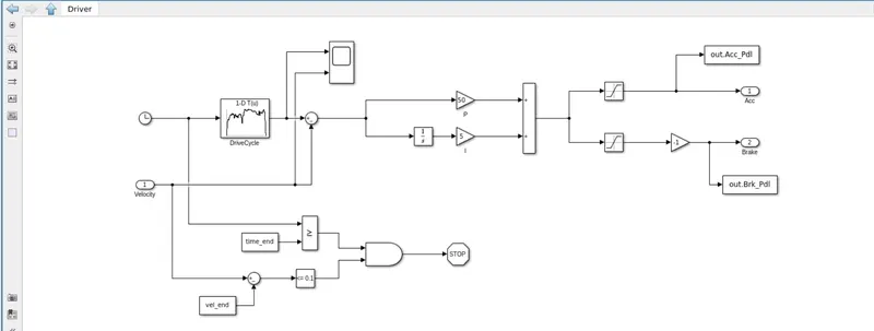
the velocity of the vehicle is given to the model and with the help of the drive cycle we can determine the acceleration and the brake of the vehicle .
this acceleration and brake is given as input to the controller unit.
A model is an abstract and simplified description of a system using mathematical equations and diagrams. The modeling concepts in this topic provide context for understanding the process of mathematically describing a system with Simulink software tools.
controller::
now lets explore the controller block.
here the inputs are acceleration,brake,velocity, state of charge, engine speed and clutchlockup.
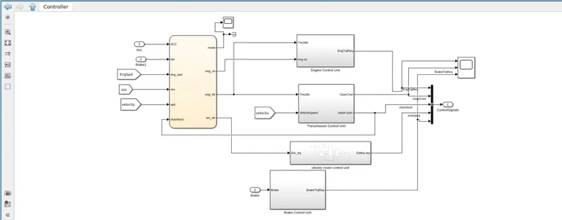
through the flow chart it selects the desired value of mode, engine torque, motor torque and engineon.
this input are fed to the remaining blocks.
The electric vehicle controller is the electronics package that operates between the batteries and the motor to control the electric vehicle's speed and acceleration much like a carburetor does in a gasoline-powered vehicle.
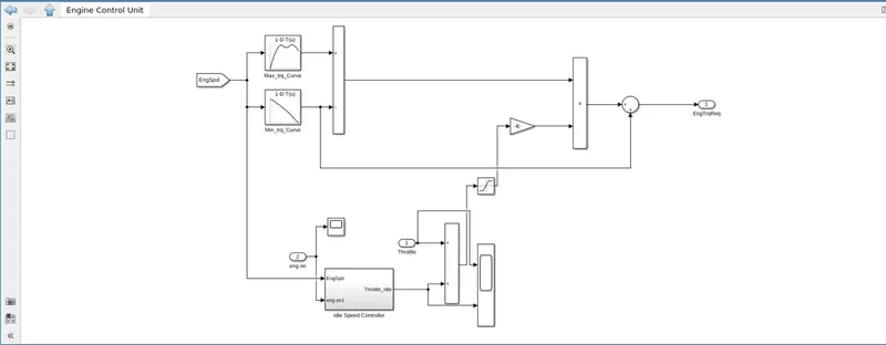
engine control unit:
this is the subsystem of the controller.
here the input is engine throttle and engine on.
and the output is engine required torque.
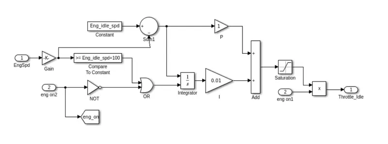
ideal speed controller:
this is used to determine the ideal condition power required. through the below we can determine the power required to the vehicle at rest condition. which is the subsystem of the engine control unit.
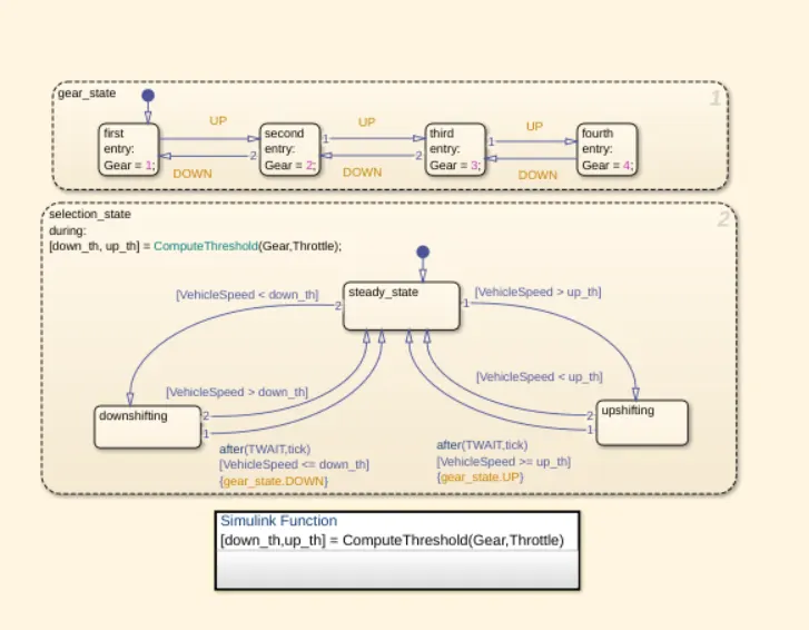
transmission control unit:
The transmission control module is an electronic component of your transmission that's in charge of interpreting electrical signals from sensors in other parts of the vehicle.
Since the TCM sends the shifting signals, a bad module can cause incorrect or unintended shifting. For example, your Honda may shift to neutral or another gear that it wouldn't normally shift into without warning. At best, it's a bit of a nuisance. At worst, it could cause a serious accident.

this is the shif logic in the transmission.
here it shows the gear transmission according to the velocity of the vehicle.
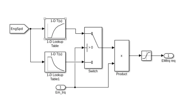
electric motor control unit:
here the input is the electric motor torque. the output is the electric motor torque required.
Motor controllers are devices that regulate the operation of an electric motor. In artificial lift applications, motor controllers generally refer to those devices used in conjunction with switchboards or variable frequency drives to control the operation of the prime mover.
brake control unit:
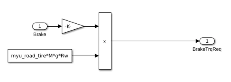
this is about the controller block set. where it is used to control the torque required to move the vehicle.
powertrain blocks::
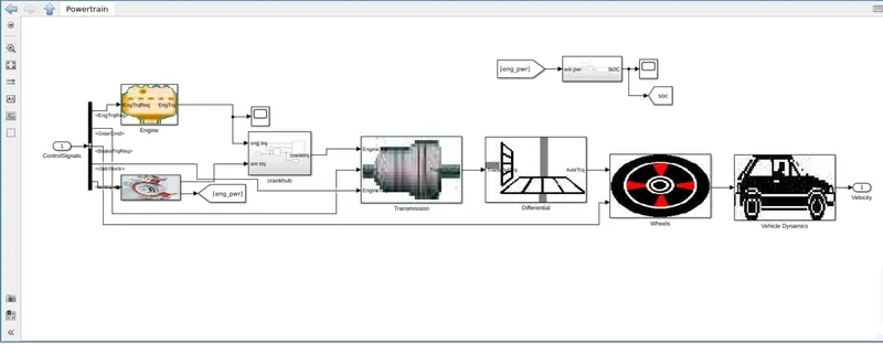
the powertrain blockset consist of the engine, motor, crankhub, transmission, differential , wheel , vehicle dynamics and vehicle dynamic.
now lets explore the powertrain one by one:
engine:
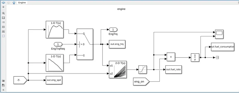
here the inputs are engine required torque and the engien torque.
which is comapared with the required torque.
electric motor:
An electric motor is an electrical machine that converts electrical energy into mechanical energy. Most electric motors operate through the interaction between the motor's magnetic field and electric current in a wire winding to generate force in the form of torque applied on the motor's shaft.They operate using principles of electromagnetism, which shows that a force is applied when an electric current is present in a magnetic field. This force creates a torque on a loop of wire present in the magnetic field, which causes the motor to spin and perform useful work.
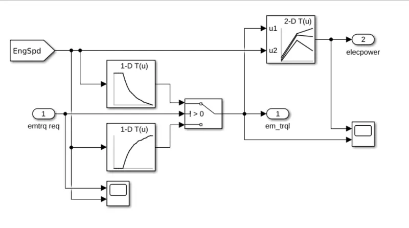
here the input are electric motor torque required and the output are electric motor torque and engine power.
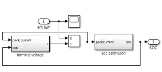
energy storage system:
Batteries are the energy storage means for EVs. Specific energy and specific power of electrochemical batteries are generally much smaller than those of gasoline.
crankhub:
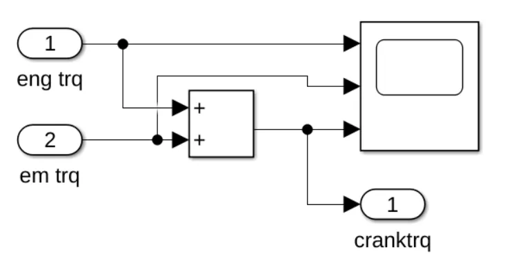
here the torque of the engine torque and the electric motor torque are added to give the crank torque.The wheel hub motor (also called wheel motor, wheel hub drive, hub motor or in-wheel motor) is an electric motor that is incorporated into the hub of a wheel and drives it directly.
transmission::
In a car, a transmission, or a gearbox, acts as the medium that transmits power generated by the engine to the wheels via a mechanical system of gears and gear trains. A transmission allows a person to apply power to a vehicle in a controlled manner, without which, the car would not efficiently move.
A transmission changes gears depending on car speed and accelerator input (i.e., how far down you push the pedal of your car) so that the engine's RPM or “revolutions per minute” are kept appropriately low. This provides two benefits: Fuel consumption is decreased. The turning gears do not overload your engine
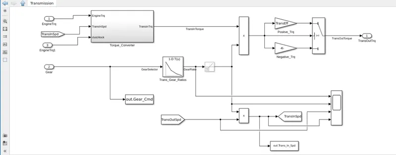
here the input is the crank torque, clutch lock and the electric torque.
Differential Model
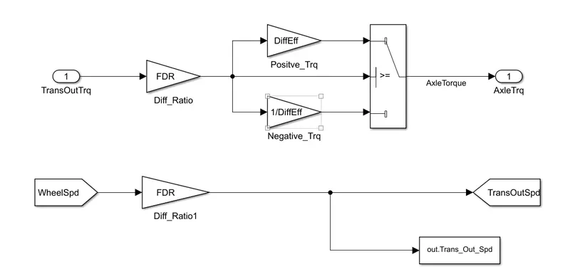
- The transmission output torque is multiplied by the differential ratio and differential efficiency in this block and the torque is transmitted to the wheel as the axle torque.
Wheel Model
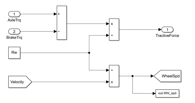
- The brake torque from the control model is subtracted from the Axle torque and divides from the rolling radius to determine the Tractive force.
- The Wheel speed is calculated from the vehicle velocity and saved in the workspace.
Vehicle Dynamics
- The longitudinal dynamics of the vehicle along with the road load is represented in the ‘Vehicle Dynamics’ block
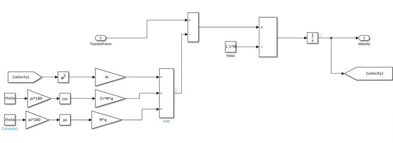
- Tractive Force and Road loads are used to calculate the vehicle velocity,
ηt⋅λt⋅TeRw=M*dVveh/dt+12ρaAfCd(Vveh+Vwd)2+CrMgcosθ+Mgsinθ">
ηt⋅λt⋅Te/Rw=MdVveh/dt+1/2ρaAfCd(Vveh+Vwd)2+CrMgcosθ+Mgsinθ
ηt⋅λt⋅Te/Rw">ηt⋅λt⋅Te/Rw= Tractive force
1/2ρa.Af.Cd(Vveh+Vwd)2+Cr.M.g.cosθ+M.g.sinθ">
1/2ρaAfCd(Vveh+Vwd)2+CrMgcosθ+Mgsinθ= Road Load
Where,
ρ a - Air Density
A f - Frontal Ares
C d - Drag Coefficient
C r - Rolling Coefficient
M - Mass of Vehicle
g - Acceleration due to gravity
θ - Slope
- The variables are loaded on the workspace using MATLAB Script.
- The Acceleration, Velocity and Distance travelled are Calculated and stored in the workspace.
5) Add additional ‘To Workspace’ blocks for transferring the desired Simulink vehicle data into the Matlab workspace.:
use to workspace command in the simulink to transfer the required data to the workspace.
6) Simulate the hybrid model on the desired drive cycles.:
Model
Post-Processing
- A MATLAB script is Created to analyse data and to generate plots. Here we rename the variables loaded from the model, do some basic post-process calculations and generate results and plots.
%% Post-Processing File
%  File for post-processing the Conventional vehicle simulation model data

%% Renaming variables
Time = out.tout;
Acc_Pdl = out.Acc_Pdl;          % Accelerator pedal [%]
Brk_Pdl = out.Brk_Pdl;          % Brake pedal [%]
Gear_Cmd = out.Gear_Cmd;        % Transmission gear
Trans_In_Spd = out.Trans_In_Spd*30/pi;  % Transmission input speed [rpm]
Trans_Out_Spd = out.Trans_Out_Spd*30/pi;% Transmission output speed [rpm]
Eng_Trq = out.Eng_Trq;          % Engine brake torque [Nm]
Eng_Spd = out.Eng_Spd*30/pi;    % Engine speed [rpm]
Eng_Fuel_Consump = out.Eng_Fuel_Consumption;    % Engine fuel consumption [g]
Veh_Dist = out.Veh_Dist/1000;   % Distance traveled by vehicle [km]
Veh_Spd = out.Veh_Spd*18/5;     % Vehicle speed [kmph]


%% Data Analysis
Eng_Pwr = Eng_Spd*pi/30.*Eng_Trq/1000;   % Engine brake power [kW]
rho_petrol = 0.7197;                    % Density of petrol [kg/L]
kmpl = Veh_Dist(end)/(Eng_Fuel_Consump(end)/1000/rho_petrol);    % Fuel economy [kmpl]


%% Plotting vehicle characteristics time trace
figure()
subplot(3,1,1)
hold on
grid on
plot(Time, Acc_Pdl, 'linewidth', 1, 'Color', 'black');
plot(Time, Brk_Pdl, 'linewidth', 1, 'Color', 'red');
ylabel('Pedal [%]')
xlim([0, Time(end)]);
legend('Accel','Brake');
subplot(3,1,2)
hold on
grid on
plot(Time, Trans_In_Spd, 'linewidth', 1, 'Color', 'black');
plot(Time, Trans_Out_Spd, 'linewidth', 1, 'Color', 'red');
ylabel('Speed [rpm]')
xlim([0, Time(end)]);
ylim([0, 6000]);
legend('Trans Input','Trans Output');
subplot(3,1,3)
hold on
grid on
plot(Time, Gear_Cmd, 'linewidth', 1, 'Color', 'black');
xlim([0, Time(end)]);
xlabel('Time [s]');
ylabel('Gear');

%% Plotting engine operating points on engine fuel map
figure('Name','Engine Operating Points');
hold on
grid on
title('Engine Operating Points','fontsize',12);
p1=plot(Eng_map_spd*30/pi,Eng_max_trq,'linewidth',2,'color','r');
p2=line([Eng_map_spd(end)*30/pi Eng_map_spd(end)*30/pi],[0 Eng_max_trq(end)]);
set(p2,'linewidth',1,'linestyle','--','color','k');
p3=line([Eng_map_spd(1)*30/pi Eng_map_spd(1)*30/pi],[0 Eng_max_trq(1)]);
set(p3,'linewidth',1,'linestyle','--','color','k');
[c,h] = contour(Eng_map_spd'*30/pi,Eng_map_trq,Eng_fuel_map');
clabel(c,h);
xlabel('Engine Speed [rpm]');
ylabel('Engine Torque [Nm]');
title('Engine Fuel Consumption Map [g/s]');
p4 = plot(Eng_Spd,Eng_Trq,'.','color','k');
legend([p1 p4],{'Max Curve','Operating Points'});
axis([Eng_map_spd(1)*30/pi Eng_map_spd(end)*30/pi 0 Eng_map_trq(end)]);
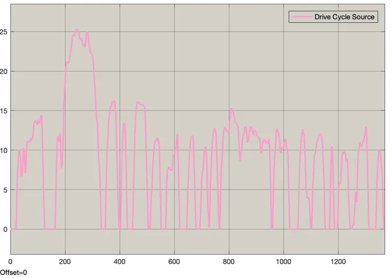
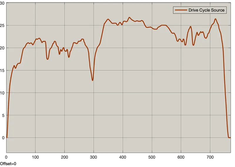
1. Drive Cycle
UDDS :
HWFET :
2. Fuel economy numbers (kmph) for UDDS and HWFET cycle.
UDDS :
For convectional Vehicle Model (Projet 1)
average speed/31.35 = maximum speed/91.99 = fuel economy/16.89
For P1 Hybrid Vehicle Model
Fuel Economy = 18.07 Kmpl
average speed/31.51 = maximum speed/91.399 = fuel economy/18.09
- Fuel economy improves as engine eliminates negative torque and negative power. Negative Energy can be revived with regional breaking.
HWFET :
For convectional Vehicle Model (Projet 1)
average speed/77.683 = maximum speed/96.99 = fuel economy/21.22
For P1 Hybrid Vehicle Model
Fuel Economy = 22.00 Kmpl
average speed/77.68 = maximum speed/96.40= fuel economy/21.67
- Fuel efficiency is slightly improved as highway has less negative power when driving. But all negative power will be regenerated with regen braking and battery SOC will increase.
- The City Fuel Economy is much lower than highway drive as the brake padel engagement and idle time on drive cycle is less.
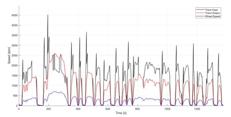
3. The Time trace for engine, Transmission input,transmission output and wheel speed
UDDS :
HWFET :
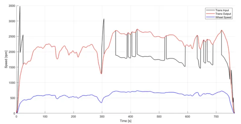
- Much of the fluctuating input speed is facilitated by the torque converter, and the transmission input speed fluctates according to the engine torque required to achieve the drive cycle.
- Wheel speed and transmission output speed vary according to gear and differential ratio.
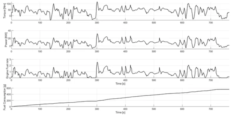
4. Engine troque, Engine power, fuel rate and fuel consumption
UDDS :
HWFET :
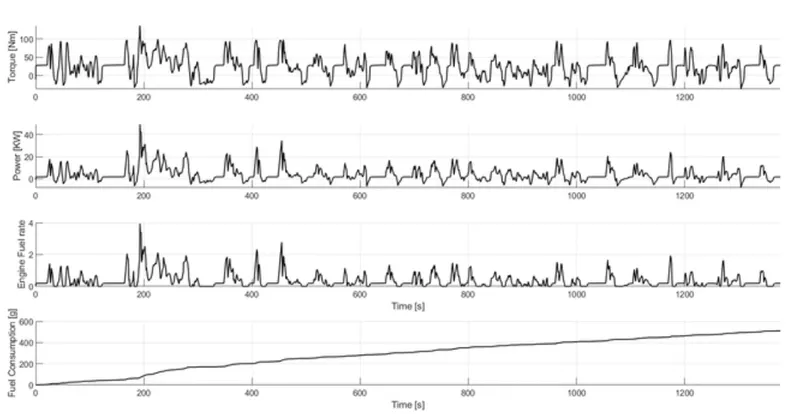
- The torque requirements of the drive cycle are different, so the fuel flow rate varies and fuel consumption is calculated.
- The HWFET drive cycle has higher power and torque requirements and less negative torque and power.
5. Accelerator and brake pedal, gear command, vehicle desired and actual speed, vehicle distance
UDDS:
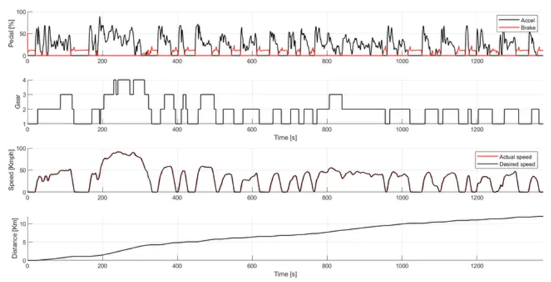
- Acceleration and brake pedals are used more because the drive cycle is not very smooth and the gear has to be shifted frequently.
HWFET:
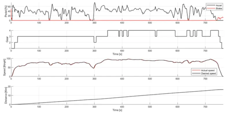
- Brake requirements are lower, more accelerator pedals are applied on the highway drive cycle, and gear shifts often occur because the drive cycle is smoother.
- Acceleration and brake pedal, the gear command of the transmission control unit, the required speed of the vehicle, the actual vehicle speed and the actual vehicle distance are plotted.
6. The engine operating points on the engine fuel map
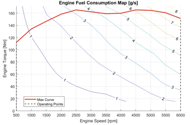
- The engine operating point are plotted on the fuel map and the operating point is under the maximum torque curve.
7. The Motor speed, torque, motor input power.
UDDS:
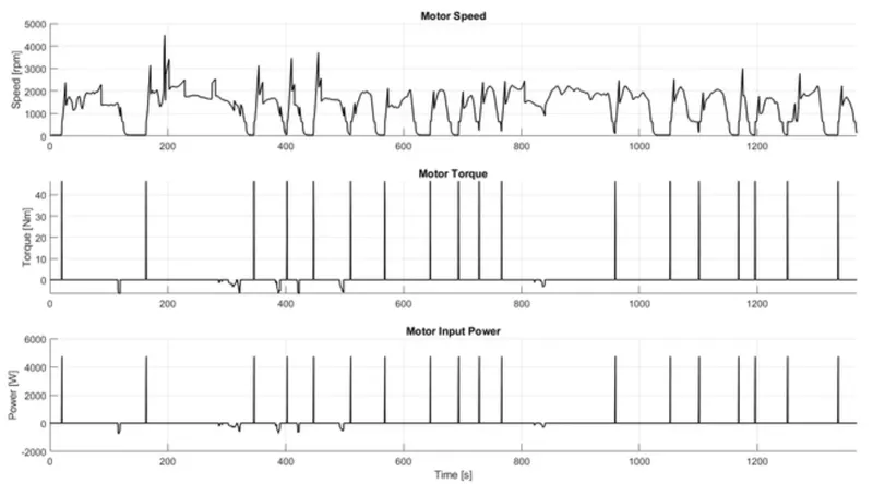
- Motor torque request is for engine start and region braking only. Electric input power is calculated by referring the motor speed according to the EM motor torque request.
HWFET:
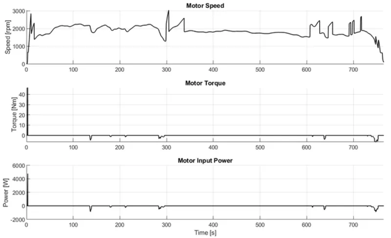
- EM motor torque demand is low as the vehicle moves at high speeds and less idle on highway drive
8. The Pack voltage, current and Soc
UDDS:
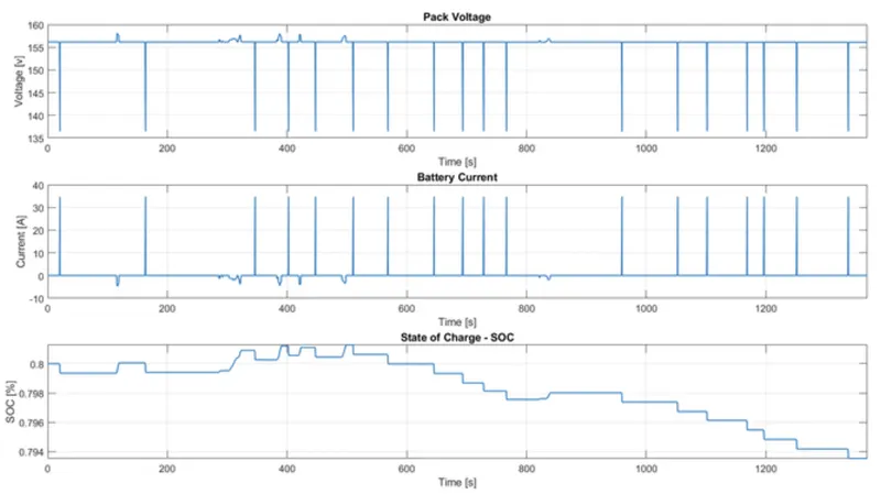
- Battery SOC is responding according to the Motor torque request and the Regen braking.
HWFET:
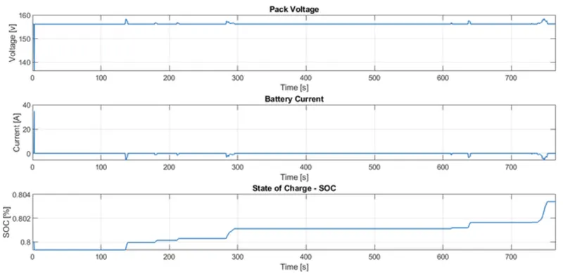
- Battery SO increases on highway drive cycles due to lower EMotor usage and region braking battery charging.
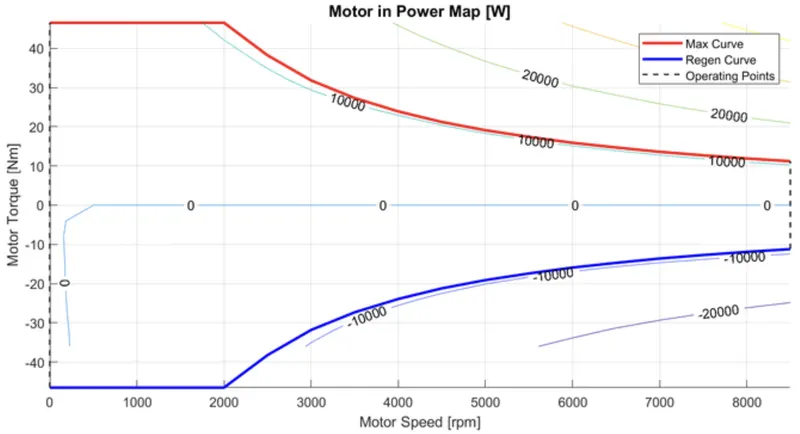
9. The motor operating points on the motor input power map, with the motor max motoring and generating
torque curves.
- Electric motor can operates between max motoring torque curve and max generating torque curve.
Conclusion :
The Various performance of characteristics and operating point of UDDS drive cycle and HWFET drive cycle are analysed and graphs are plotted.
- Time trace for engine, Transmission input, Transmission output and wheelspeed with respect to time.
- Engine torque, Engine power, Fuel rate and Fuel consumption with respect to time.
- Accelerator and brake pedal, gear command and vehicle desired, actual speed, vehicle distance with respect to time.
- Engine operating points on the engine fuel map with respect to time
- Motor speed, Torque, Motor input power with respect to time.
- Pack voltage, Current and State of charging with respect to time.
- The motor operating points on the motor input power map with respect to time.
and also it comparing with HWFET drive cycle and their numbers also compared.
Referance::
1,https://afdc.energy.gov/vehicles/how-do-hybrid-electric-cars-work