Project 2
Aim: Using MATLAB/simulink and the drive cycle from the attached excel sheet, find-
- The max heat generation of the battery
- The SOC of the battery at 2 *104second of the battery operation
1-The max heat generation of the battery
Given data,
Consider the battery resistance is 0.5 mOhm, delta time is 0.1 and entropic factor is 2
battery resistance = 0.5mohm
delta time = 0.1
entropic factor = 2
I= -0.896
calculation:
Maximum heat genereted = I^2Rt
=(-0.896)^2*0.5*0.1
= 0.0401
Maximum heat generated = maximum joule heat+2(max joul heat)
= 0.0401+2(0.0401)
= 0.1203
2-The SOC of the battery at 2 *104second of the battery operation
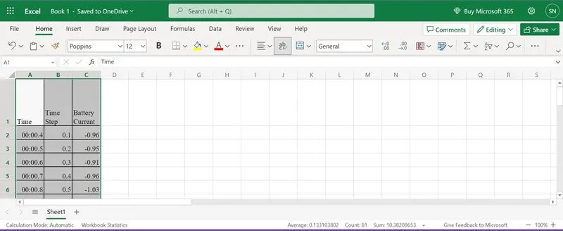
| Time | Time Step | Battery Current |
| 00:00.4 | 0.1 | -0.9632 |
| 00:00.5 | 0.2 | -0.952 |
| 00:00.6 | 0.3 | -0.9072 |
| 00:00.7 | 0.4 | -0.9632 |
| 00:00.8 | 0.5 | -1.0304 |
| 00:00.9 | 0.6 | -0.9632 |
| 00:01.0 | 0.7 | -1.0304 |
| 00:01.1 | 0.8 | -1.008 |
| 00:01.2 | 0.9 | -0.9856 |
| 00:01.3 | 1 | -0.9632 |
| 00:01.4 | 1.1 | -0.9184 |
| 00:01.5 | 1.2 | -0.9296 |
| 00:01.6 | 1.3 | -0.9296 |
| 00:01.7 | 1.4 | -0.9296 |
| 00:01.8 | 1.5 | -0.9184 |
| 00:01.9 | 1.6 | -0.9408 |
| 00:02.0 | 1.7 | -0.896 |
| 00:02.1 | 1.8 | -0.9072 |
| 00:02.2 | 1.9 | -0.9072 |
| 00:02.3 | 2 | -0.9408 |
| 00:02.4 | 2.1 | -0.9296 |
| 00:02.5 | 2.2 | -0.9296 |
| 00:02.6 | 2.3 | -0.9968 |
| 00:02.7 | 2.4 | -0.9968 |
| 00:02.8 | 2.5 | -0.9408 |
| 00:02.9 | 2.6 | -0.9408 |
| Battery resistance | 2 milli ohm |
Theory:
In EVs, regenerative braking technology is used that time vehicle battery SOC measurement occurs in running cindition.
Regenerative brakes work by reversing electric motors that propel a car. It works like a generator and feeds energy back into the hybrid or electric system to help replenish a little bit of range. These small boosts in battery range can accumulate and improve efficiency over time when used regularly.
Drivers can activate regenerative brakes in a few different ways. Some hybrid and electric cars have a paddle by the steering wheel that activates the regenerative brakes. However, activation is seamless in most cars with regenerative braking. Applying the regular brake pedal with your foot makes the regenerative and friction brakes work together to slow down the vehicle. Cars with an especially aggressive system can use regenerative brakes when the car is coasting. Sometimes called one pedal driving, drivers may use the feature while in a specific drive mode that emphasizes efficiency on longer trips.
Although regenerative brakes use different engineering than friction brakes, it achieves the same goal of slowing down and stopping a moving car. Since it has the same effect as regular brakes, the brake lights still come on when using regenerative brakes as a safety measure.
For example, say you’re driving a Nissan leaf in e-Pedal mode. When you lift your foot off the accelerator, the regenerative brakes activate automatically. At the same time, the brake lights on the back of the car turn on like they would if you were to depress the brake pedal.
I build the simulink model in simulink used blocks as shown below:
1- Signal Builder
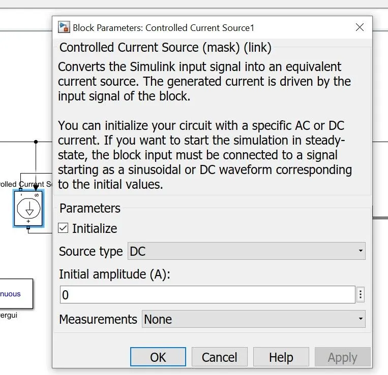
2-controlled current source
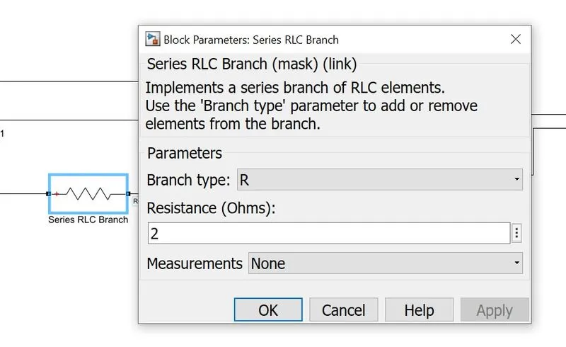
3- series RLC circuit(resistance)
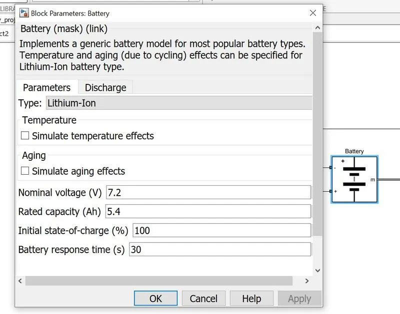
4-Battery
5-Bus selector
6-scope
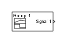
The Signal Builder block allows you to create interchangeable groups of piecewise linear signal sources and use them in a model. You can quickly switch the signal groups into and out of a model to facilitate testing. In the Signal Builder window, create signals and define the output waveforms. To open the window, double-click the block. See signal groups.

The Controlled Current Source block converts the Simulink input signal into an equivalent current source. The generated current is driven by the input signal of the block. The positive current direction is shown by the arrow in the block icon.
You can initialize the Controlled Current Source block with a specific AC or DC current. If you want to start the simulation in a steady state, the block input must be connected to a signal starting as a sinusoidal or DC waveform corresponding to the initial values.

The Series RLC Branch block implements a single resistor, inductor, capacitor, or a series combination of these. Use the Branch type parameter to select elements you want to include in the branch.
Negative values are allowed for resistance, inductance, and capacitance.

The Battery block implements a generic dynamic model that represents most popular types of rechargeable batteries.
The state of charge (SOC) for a battery is a measure of battery's charge, expressed as a percent of the full charge. The depth of discharge (DOD) is the numerical compliment of the SOC, such that DOD = 100% - SOC.
For example, if the SOC is:
-
100% — The battery is fully charged and the DOD is 0%.
-
75% — The battery is 3/4 charged and the DOD is 25%.
-
50% — The battery is 1/2 charged and the DOD is 50%.
-
0% — The battery is has 0 charge and the DOD is 100%

The Bus Selector block outputs the elements you select from the input bus. The block can output the selected elements separately or in a new virtual bus.
The Bus Selector block does not support mixing message and signal elements as outputs.
I connect all blocks to each other and build the simulink model as shown below:
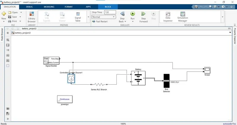
After building the module in simulink double click to signal builder go into the file section and import the file. I make an Xl file https://1drv.ms/x/s!AnCF7BD_X93dgwCPJ83gijLTyJHU?e=yXaUAg and import the file in signal builder as shown below.
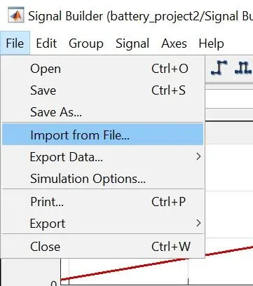
After importing signal builder shows data graph.
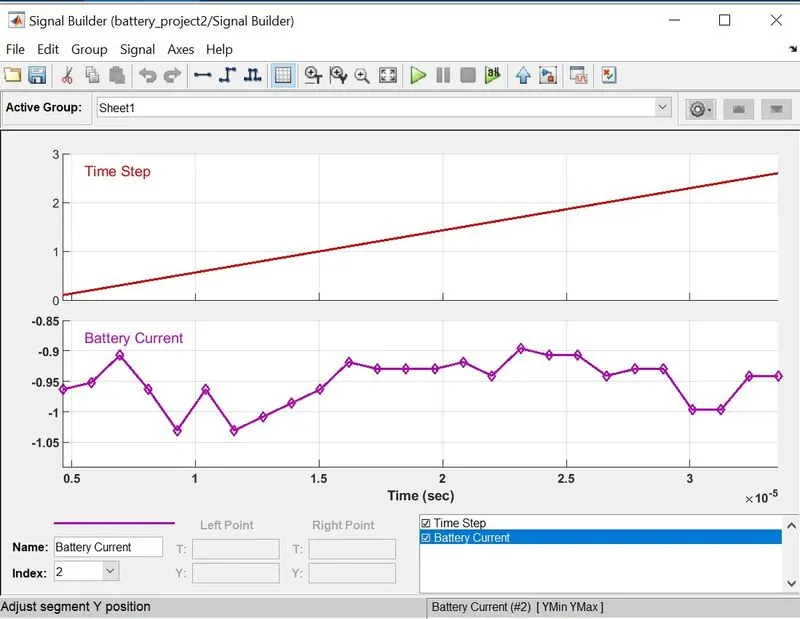
After importing the data in signal builder i set the stop time as 130sec and run the module
and analyze the data in scope as shown below.
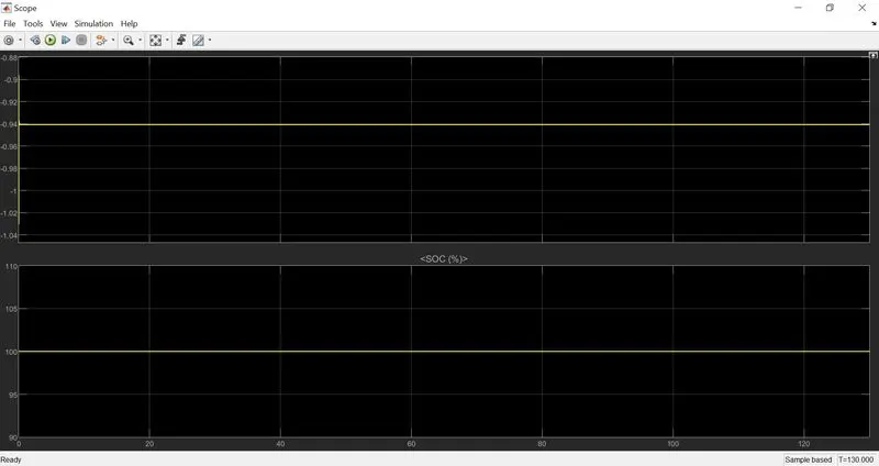
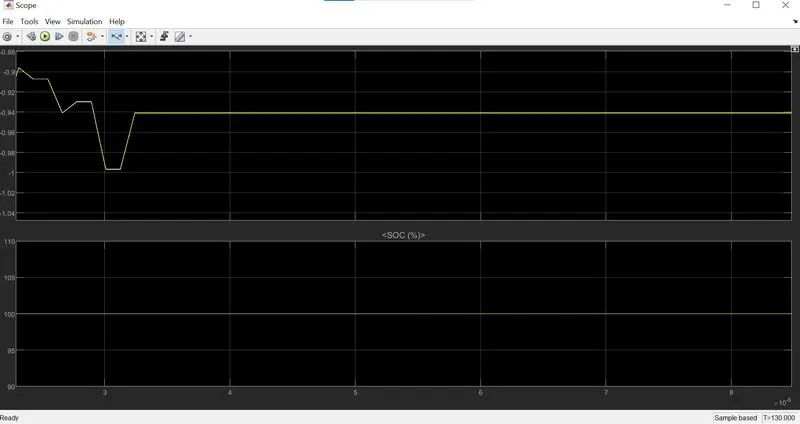
SOC state of charge is 100% because the current is negative means the vehicle run in the reverse direction and soc is always at 100%.
Time is fluctuate at the time of starting the stable constantly.
conclusion:
1- calculate the maximum heat generation.
2- make a simulink module and analyze the SOC.