Energy analysis for a driving cycle
- Aim : Simulink model for the energy analysis of an EV on a driving cycle.
- Workflow and Equations : The whole idea of the model and the governing equations is as follows:
- In this model we will calculate the different forces acting on the vehicle while it runs for a specific drive cycle and analyse the power and energy flow for the vehicle in that driving cycle.
- The driving cycle will feed the velocity input and the other paramaters associated with the vehicle are taken for the toyota prius. The forces are calculated according to the governing equations and then power and energy is calculated using the integerator block.
- The forces we considering acting on the vehicle are forward acceleraton force, rolling resistance, aerodynamic drag and hill climbing force. Each force is calculated and added to get the tractive force, from which the power and energy is calculated.
- The goverening equation are the tractive force equation and power equation given below :
- The total Traction force is `T_f = ma + 1/2rhoC_dAv^2 + mgsintheta + mu_rmg` where
- m is the mass of the vehicle
- a is the forward acceleration
- g is the acceleration due to gravity
- `rho` is air density taken for dry air
- `C_d` is the drag cofficient
- A is the frontal area
- v is the velocity
- `theta` is angle of inclination
- `mu_r` is the rolling resistance cofficient
- The Power is as `P = T_f*v` and energy is as `E = intP.dt`
- Model and Explanation :
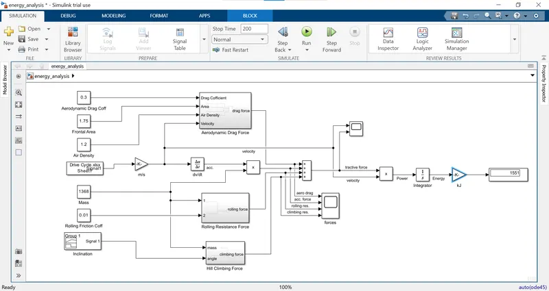
- In the model we use the from spreadsheet block to load the driving cycle velocity data to the model and the constant blocks are used for the parameters associated with vehicle and the signal builder is used to feed the inclination at specific time period accordingly to the velocity for that time period.
- The speed is in kmph that we need to convert into m/s so the gain block does that. The derivative block is used to get the acceleration for the given drive cycle. The forces are calculated by mutiplying the specific parameters to get the required values according to the equations.
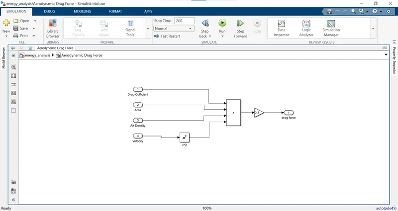
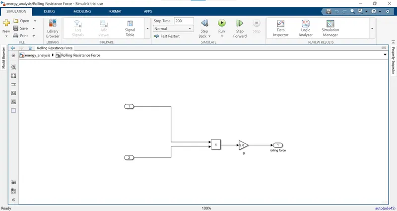
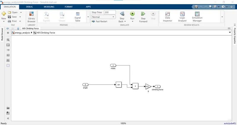
- After we have calculated all the forces we use the sum block to add them up to get the total tractive force which then is multiplied with the velocity to get the total power and then using the integrator block we get the total energy converted into kJ using the gain block.
- Results :
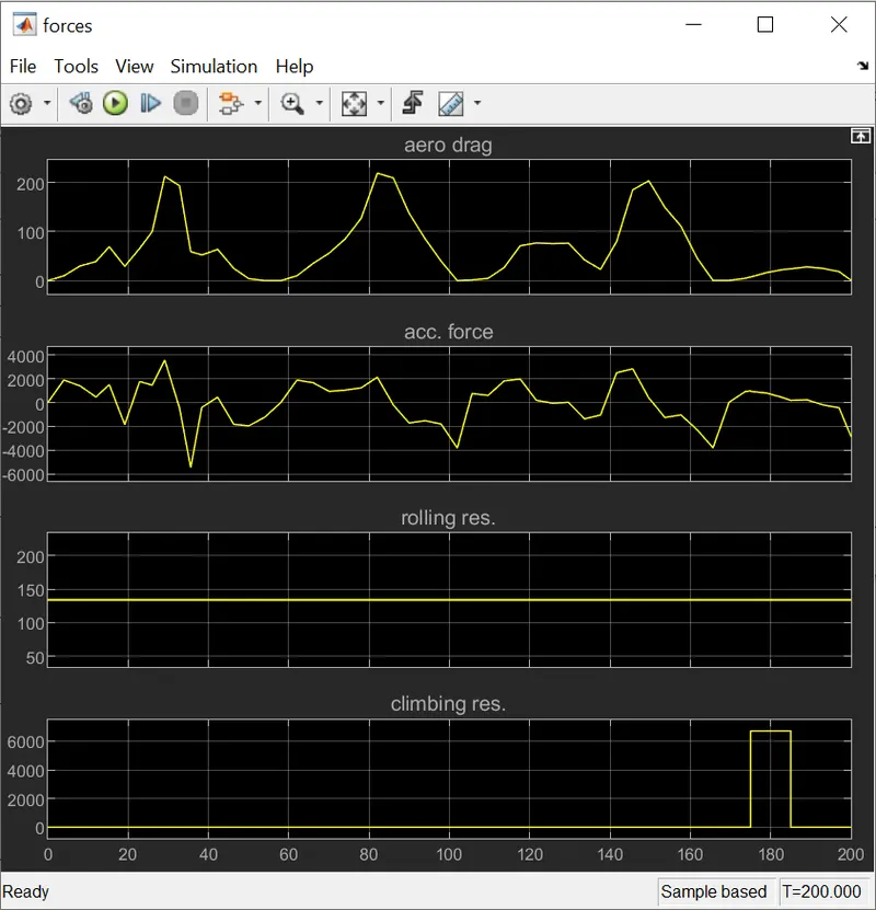
- We can see each of the forces calculated over the drive cycle. The rolling resistance force remains constant throughout as we not considering any changes with the rolling cofficient. The aerodynamic drag is changing according to the velocity and the forward acceleration is changing according to the acceleration.
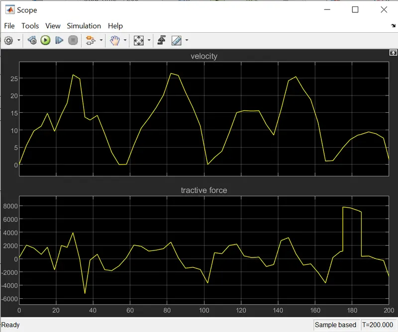
- We can see how the total tractive force is varying according to the velocity of the vehicle. As soon as the vehicle speed is increasing the tractive force slope is positive and the slope is directly proportional to the acceleration and in case the vehicle is deaccelerating the slope is negative.
- We can also see as start climbing uphill of an inclination of 30 degree the tractive force shoots up directly because the at time of 175 sec. the inclination is introduced while the vehicle is also accelerating.
The model and drive cycle link :
https://drive.google.com/file/d/1BglkKHdscrfxm_A_3VyrLpqM9DVYMqFE/view?usp=sharing, https://docs.google.com/spreadsheets/d/1fcVKFCzo6LkrT9GAoGjADQoZfG-gYX_E/edit?usp=sharing&ouid=102080933020619898882&rtpof=true&sd=true
The modelling is not done in the simscape or the physical modelling as the powertrain blockset is not available in trial version and the we need to longitudnal driver block which helps in feeding the right power supply to the motor according to the velocity in drive cycle, for that we need to design the PI control method.