Project 2
DELIVERABLES:
AIM:
The aim of the project entitled ‘Project: Ajman Waste Water Treatment Plant Capacity Upgrade Works is to reviewing the given factual report of the proposed site and creating the geotechnical interpretative report and ground model for the proposed site.
INTRODUCTION:
The geotechnical interpretative report has been made for the proposed site which is to be built in the recommended area. After conducting 40-50hr of project, the 2 boreholes, is performed to depths of 20.00 m (BH2) and 30.00 m (BH1) respectively below the existing ground surface. Logs of
In the project attached, review of the factual report and prepare a detailed geotechnical interpretative report capturing the following
- Factual data Interpretations
- geological cross-sections
- Summary of ground model
- Estimation of bearing capacity and subgrade modulus of the water tank.
ANSWER 1:
GEOLOGICAL CROSS- SECTION:
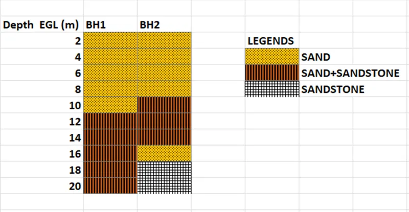
ANSWER 2:
The geotechnical interpretative report is prepared by the geotechnical engineer. From Desk study data to field data and laboratory data are reviewed thoroughly and then the geotechnical model suitable for the project is been made. The geotechnical interpretative report consists of the following:
INTRODUCTION:
- COMPANY’S NAME: Geoscience Testing Laboratory (GTL), M/s. Ajman Sewerage (Private) Company Limited, M/s. Six Construct (contractor).
- PURPOSE: Establishment of the soil / rock profile and the ground water conditions, general characteristics and variability of the ground.
- TYPES OF FIELDS WORKS: Two (02) boreholes, in which One (01) borehole drilled down to a depth of 30.0m & the other borehole drilled down to a depth of 20.0 m, below existing ground level (EGL).
- SITE: Emirates of Ajman; United Arab Emirates about 4 kms from the Sheikh Mohammad Bin Zayed Road (E311) and just 8 kms from the Arabian Gulf.
- The borehole locations are provided by the contractor M/s. Six Construct for the proposed Waste Water Treatment Plant Capacity Upgrade Works.
SITE DESCRIPTION:
- Local excavation to 3m was executed at the location of the exploratory holes in order to check for services. Excavated material was used as the backfill material for the trail pits before starting of the bore holes.
- The test location and its levels were set by the surveyor of the M/S Six Construct company.
- Existing ground level: +21.0m AMD
- Groundwater level: 9.50-9.60
GROUND INVESTIGATION:
- The assigned geotechnical works includes the following works.
|
SN. NO. |
TEST AND THE AREAS |
DEPTH (m) |
NOS OF BORE HOLES |
|
1 |
Borehole |
20 |
1 |
|
2 |
Borehole |
30 |
1 |
|
3 |
Cone Penetration Test |
15 |
12 |
|
4 |
Trail Pits |
3 |
2 |
|
5 |
Standpipe Piezometer |
2 |
GROUND CONDITION:
- Stratigraphy for BH1:
|
Depth (below EGL) |
Description |
|
0.00 - 2.50 |
MADE GROUND Light brown/ brown, slightly silty fine-grained SAND. |
|
2.50 - 4.00 |
Dense, light brown/brown slightly silty fine-grained SAND. |
|
4.00 - 10.0 |
Dense to very dense, brown, slightly silty to silty, fine-grained SAND, with some cemented SANDSTONE pieces. |
|
10.00 – 30.0 |
Very dense, brown / reddish brown, gravelly, slightly silty to silty/locally very silty, fine to medium grained SAND. With some amount of cemented sand pieces and gravels |
- Stratigraphy for BH2:
|
Depth (below EGL) |
Description |
|
0.00 – 2.50 |
MADE GROUND Light brown/ brown, slightly silty fine-grained SAND. |
|
2.50 – 6.00 |
Medium dense to dense, light brown/brown, slightly silty fine-grained SAND with some cemented sand pieces. |
|
6.00 – 16.18 |
Very dense, light brown/brown, gravelly to very gravelly, slightly silty to silty, fine-grained SAND with some cemented sand pieces |
|
16.18 – 20.0 |
Extremely weak to very weak, light brown/ brown, very thinly to thinly bedded SANDSTONE |
SPT RESULTS:
|
BOREHOLES |
ELEVATION (m) |
THICKNESS(m) |
N SPT |
DESCRIPTION |
|
|
FROM |
TO |
||||
|
BOREHOLE 1 |
0.00 |
2.50 |
2.50 |
0 |
FINE SAND |
|
2.50 |
4.00 |
1.50 |
43 |
FINE SAND |
|
|
4.00 |
10.00 |
6.00 |
240 |
FINE SAND |
|
|
10.00 |
11.00 |
1.00 |
200 |
FINE SAND |
|
|
11.00 |
12.00 |
1.00 |
170 |
FINE SAND |
|
|
12.00 |
13.00 |
1.50 |
180 |
FINE SAND |
|
|
15.00 |
17.00 |
2.00 |
200 |
FINE SAND |
|
|
18.00 |
20.00 |
2.00 |
160 |
VD SAND |
|
|
20.70 |
21.00 |
0.30 |
125 |
VD SAND |
|
|
22.00 |
22.20 |
0.20 |
105 |
VD SAND |
|
|
23.00 |
25.00 |
2.00 |
180 |
VD SAND |
|
|
26.00 |
27.00 |
1.00 |
160 |
VD SAND |
|
|
28.00 |
30.00 |
2.00 |
145 |
VD SAND |
|
|
BOREHOLE 2 |
0.00 |
2.50 |
2.50 |
0 |
FINE SAND |
|
2.50 |
6.00 |
3.50 |
50 |
FINE SAND |
|
|
6.00 |
7.20 |
1.20 |
210 |
VD SAND |
|
|
8.00 |
9.20 |
1.20 |
170 |
VD SAND |
|
|
11.00 |
12.00 |
1.00 |
160 |
VD SAND |
|
|
13.00 |
16.00 |
3.00 |
155 |
VD SAND |
|
CONE PENETRATION TEST:
|
CPT NO. |
Cone resistance [2] |
Local friction [3] |
Pore pressure u2[6] |
|
MPa |
KPa |
KPa |
|
|
CPT 1 |
30 |
360 |
1 |
|
CPT 2 |
34 |
600 |
0-1 |
|
CPT 2-A |
34 |
490 |
0-1 |
|
CPT 2-B |
32 |
372 |
0 |
|
CPT 3 |
38 |
482 |
0 |
|
CPT 4 |
26 |
242 |
0 |
|
CPT 4-A |
29 |
238 |
0 |
|
CPT 4-B |
42 |
440 |
0 |
|
CPT 5 |
>50 |
300 |
0 |
|
CPT 6 |
32 |
160 |
0 |
|
CPT 6-A |
33 |
270 |
0 |
|
CPT 7 |
22 |
220 |
0 |
GEOHAZARDS:
Following are the parameters which is to be identified under this:
- Loose material or with high percentage of fines.
- Liquefaction issues.
- High water table.
- Unsuitable ground conditions.
GROUNDWATER TABLE:
|
Boreholes nos. |
Piezometer nos. |
End of piezometer depth (EGL) |
GW reduced level (below EGL) |
|
BH 1 |
1 |
21 |
9.50 |
|
BH 2 |
1 |
19 |
9.60 |
LABORATORY RESULTS:
SUMMARY OF LABORATORY RESULTS (BOREHOLES 1 & 2)
|
BOREHOLE ID |
SAMPLE TYPE |
DEPTH (m) |
GRAVEL % |
SAND % |
SILT/CLAY % |
UCS (MPa) |
MOISTURE CONTENT % |
POINT LOAD INDEX (MPa) |
|
BH1 |
SOIL |
2.50 |
0 |
99.0 |
1.0 |
- |
- |
- |
|
4.00 |
0 |
95 |
5.0 |
- |
- |
- |
||
|
9.00 |
0 |
93 |
7.0 |
- |
- |
- |
||
|
13.50 |
14 |
65 |
21 |
- |
- |
- |
||
|
14.70 |
5 |
84 |
11 |
- |
- |
- |
||
|
18.25 |
11 |
86 |
3 |
- |
- |
- |
||
|
24.00 |
1 |
97 |
2 |
- |
- |
- |
||
|
28.00 |
10 |
87 |
3 |
- |
- |
- |
||
|
BH2 |
SOIL |
1.00 |
1 |
97 |
2 |
- |
- |
- |
|
2.50 |
1 |
96 |
3 |
- |
- |
- |
||
|
5.0 |
0 |
95 |
5 |
- |
- |
- |
||
|
10 |
0 |
98 |
2 |
- |
- |
- |
||
|
15 |
1 |
94 |
5 |
- |
- |
- |
||
|
16 |
29 |
59 |
12 |
- |
- |
- |
||
|
ROCK |
16.28 |
- |
- |
- |
- |
17 |
0.8 |
|
|
18.00 |
- |
- |
- |
1.4 |
17 |
- |
SUMMARY OF CHEMICAL RESULTS (BOREHOLE 1 & 2)
|
BOREHOLE ID |
SAMPLE TYPE |
DEPTH |
CHLORIDE % (Mg/L) |
SULPHATE % (Mg/L) |
pH |
|
BH 1 |
SOIL |
1.00 |
142 |
74 |
8.3 |
|
3.00 |
57 |
74 |
8.0 |
||
|
GROUNDWATER |
9.50 |
284 |
94 |
8.9 |
|
|
BH 2 |
SOIL |
1.50 |
85 |
74 |
8.2 |
|
2.00 |
170 |
140 |
8.2 |
||
|
GROUNDWATER |
9.60 |
284 |
86 |
8.9 |
PROPOSED GROUND MODEL:
|
Description
|
Elevation
|
Thickness
|
N- SPT
|
RQD |
|
BOREHOLE 1 |
||||
|
FINE SAND |
0.00-2.50 |
2.50 |
0 |
0 |
|
FINE SAND |
2.50-4.00 |
1.50 |
43 |
0 |
|
FINE SAND |
4.00-10.00 |
6.00 |
240 |
0 |
|
FINE SAND |
10.0-11.0 |
1.00 |
200 |
0 |
|
FINE SAND |
11.0-12.0 |
1.00 |
170 |
0 |
|
FINE SAND |
12.0-13.0 |
1.00 |
180 |
0 |
|
FINE SAND |
15.0-17.0 |
2.00 |
200 |
0 |
|
VD SAND |
18.0-20.0 |
2.00 |
160 |
0 |
|
VD SAND |
20.7-21.0 |
0.30 |
125 |
0 |
|
VD SAND |
22.0-22.2 |
0.20 |
105 |
0 |
|
VD SAND |
23.0-25.0 |
2.00 |
180 |
0 |
|
VD SAND |
26.0-27.0 |
1.00 |
160 |
0 |
|
VD SAND |
28.0-30.0 |
2.00 |
145 |
0 |
|
BOREHOLE 2 |
||||
|
FINE SAND |
0.00-2.50 |
2.50 |
0 |
0 |
|
FINE SAND |
2.50-6.00 |
3.50 |
50 |
0 |
|
VD SAND |
6.00-7.20 |
1.20 |
210 |
0 |
|
VD SAND |
8.00-9.20 |
1.20 |
170 |
0 |
|
VD SAND |
11.0-12.0 |
1.00 |
160 |
0 |
|
VD SAND |
13.0-16.0 |
3.00 |
155 |
0 |
|
SANDSTONE |
16.0-20.0 |
4.00 |
0 |
12 |
EARTH WORKS:
- The backfilling of the material is to be carried out should be mentioned in it and it should be done in the compact layers.
- 98% of maximum dry density and verified using sand replacement method.
GROUND MODEL SUMMARY:
- A ground model shall be formed of the geological, hydrogeological and geotechnical conditions at, under, and around the site and the characteristics, variability and uncertainty of those conditions.
- The area consists maximum of fine to very dense sand with the sandstone as the basement rock.
- The pile foundation is required for the stability of the foundation.
- Proper ground improvement methods are required before the construction.
- Ground improvement methods such as- jet grouting, dynamic compaction, deep soil mixing.
- The area is prone to liquefaction therefore the proper techniques should be taken into consideration for the ground improvement.
- Therefore, to deal with the liquefaction the appropriate number of gravels should be added to the ground improvement techniques.
- The ground water level is near about 9.50 m bgl having high amount of chloride content, so the foundation should be made accordingly.
ANSWER 3:
- Safe bearing capacity (qu) = 1.3 CNc + qNq + 0.4ϒBNϒ
Given: diameter of water tank= 23m; ϒ= 21kN/m3; Nϒ= 115
Therefore, SBC = ½ x 21 x 23 x 115 = 22,218 KPA
- Subgrade modulus (Ks)= Load/ Settlement
Given: estimated settlement= 40 mm; foundation pressure= 200 KPa
Therefore, Ks = 200 x π/4* (23)2/ 0.04 m = 20,76,325 MN/m3