Project 1
AIM:
The aim of the project entitled ‘’Geotechnical investigation and subsurface exploration’’ is to reviewing the given proposed site and locating all the field tests on the given site layout.
INTRODUCTION:
The geotechnical specification report has been conducted for the proposed site which is to be build in the recommended area. After conducting 40-50hr of project, the total of 41 boring, is to be performed to depths of approximately 10-15 feet below the existing ground surface. Logs of the borings along with a site location map and boring location plans are included in the report.
The purpose of these services is to provide information and geotechnical recommendation related to:
- Subsurface soil and rock conditions.
- Groundwater conditions.
- Different types of tests to determine the soil and rock strength.
- Earthworks.
- To determine that does the site falls below the acceptable risk level.
- Proper ground improvement methods.
ANSWER 1:
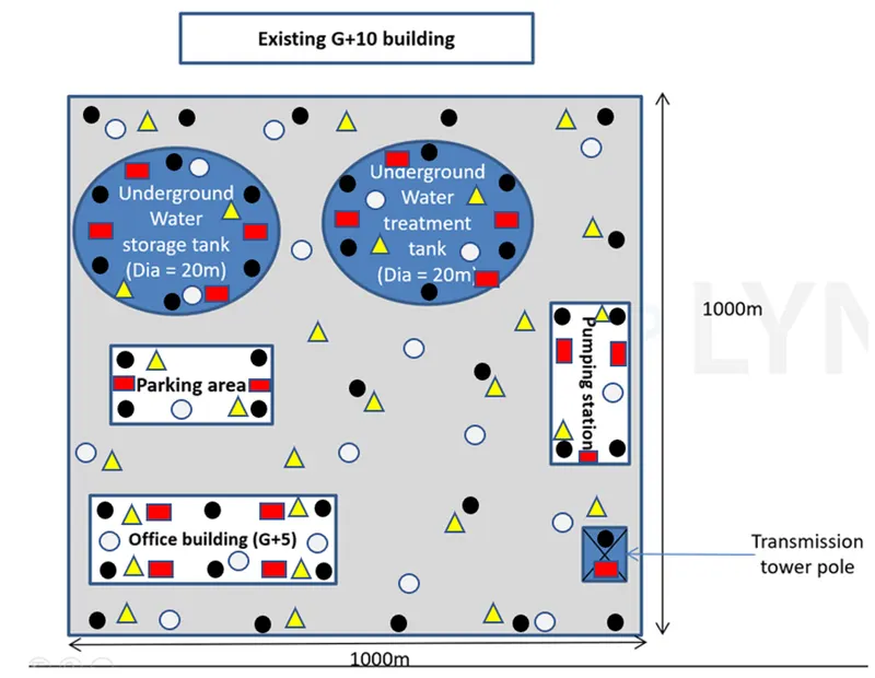
 |
Boreholes (BH) - 41 |
|
|
Cone-penetration test (CPT) - 27 |
|
Plate-load test (PT) - 18 |
|
 |
Trail pit (TP) -21 |

ANSWER 2:
TECHNICAL SPECIFICATION:
SCOPE:
Soil exploration work includes the two fundamental aspects, first is the field test and the second is the laboratory test to evaluate the area and prepare the detailed report including the recommendation. Following are some of the aspects which is taken into consideration:
- The scope of the project is to identify the type of the foundation on which the workshop building is to be constructed. This could be done through the walk over survey in the area
- The type of the foundation system to be installed.
- Depth of the foundation
- 41 borehole is required. 26 boreholes of 15-20 m depth in the water storage tank, water treatment tank, parking area, pumping station and office building area and 15 boreholes of 8-10 m depth are required in the rest of the areas including the pavement area.
- 27 cone penetration test is to be conducted up to refusal.
- Requirement of 20 piezometers for observing the groundwater level in the borehole area.
- Requirement of 21 trail pits up to depth of 3-4 m
- Requirement of 18 plate load test is required to identify the total bearing capacity of the strata where the foundation is to be constructed.
- 82 laboratory test is to be conducted which includes 2 test per borehole to identify the particle size analysis, Atterberg limits, specific gravity, bulk density, moisture content of the soil.
- 82 laboratory test is to be conducted which includes 2 test per borehole to identify the Shear strength of the soil which includes triaxial compression test, direct shear test.
- 82 laboratory test is to be conducted which includes 2 test per borehole to identify the unit weight, specific gravity, porosity of the rock in the strata.
- 82 laboratory test is to be conducted which includes 2 test per borehole to identify the uniaxial compression strength of the rock strata and point load test.
- 41 chemical analysis test is to be conducted to identify the pH, chlorine, sulphate and organic content of the soil.
CODES AND STANDARDS:
- IS: 1490- Classification and identification of soils for general engineering purposes.
- IS: 1888- Method of load test on soil.
- IS: 1892- subsurface investigation for foundation.
- IS: 1904- Structural safety of building (shallow foundation).
- IS: 2131- Methods of standard penetration test.
- IS: 2132- Code of practice for thin-walled tube sampling of soils.
- IS: 2720- Methods of test for soils.
- IS: 2809- Glossary of items and symbols relating to soil engineering.
- IS: 3025- Methods of sampling and testing for water used.
- IS: 3043- Code of practise for earthing.
- IS: 4078- Indexing and storage of drilling cores.
- IS: 4438- Code of practise for in-situ vane shear tests for soils.
- IS: 4453- Code of practise for exploration of pits, trenches, drifts and shafts.
- IS: 4464- Presentation of drilling information and core description in foundation investigation.
- IS: 4968- Dynamic core penetration test.
- IS: 4968 (Part II)- Static cone penetration test.
- IS: 5249- Methods of test for determination of dynamic properties of soil.
- IS: 5313- Guide for core drilling observation.
- IS: 6935- Methods for determination of water level in bore holes.
- IS: 7746- In-situ shear test on rock.
- IS: 8763- Guide for undisturbed sampling of beds.
- IS: 9179- Methods for preparation of rock specimen for laboratory testing.
- IS: 10108- Sampling of soils by thin wall samples with stationary piston.
SOIL EXPLORATION:
BORING TEST-
Boring test through different layers of soil shall be carried out by the contractor at the location which is marked in the drawing or by the instruction of the engineer in a manner described below:
- Boring method as described in the IS: 1892 may be adopted.
- Minimum diameter of the boring shall be 150 mm.
- During the boring operation if the rock strata is not encountered then the boring shall be continued up to 20 m for 26 boreholes and up to 10 m for the remaining boreholes.
- Spacing of the borehole shall be 20-25 m.
- In case of presence of hard material/ boulders, it should be chopped using copping bits and the debris should be removed before the restoration of drilling.
- Ground water level of the borehole shall be checked and recorded in the bore log.
- Sub-soil water samples shall be collected from the borehole for moisture determination.
- Back-filling should be done by the contractor using sand fills when directed by the engineer.
STABLISATION OF BOREHOLE-
- Casing tubes shall be established in the bore hole by means of drilling fluids which is the mixture of bentonite and water.
- Grouting of rock strata shall be done wherever required.
SAMPLING-
- Undisturbed samples should be collected from every 1.5 m or when there is any change in the strata.
- Collecting of samples from the boreholes should not exceed 3.0 m in any case.
- In case of uniformity in the characteristic of the soil, the geotechnical engineer may limit the number of samples.
TUBE SAMPLING-
- Open drive thin wall tube sampler shall be attached to the rod to obtain the undisturbed samples.
- Samplers to be used should have area ratio less than 13-10%.
- Head should have checked valve and port to permit easy escape of drilling fluid and air.
- Jacking and driving technique should be used depending on the type of the soil.
- Samples should be taken out carefully after the completion of sampling operation.
- 1 inch of soil should be removed from each end.
- Surface water should be removed from the soil with the help of soaking paper.
- Samples should be packed in the air tight container marked with the tube sampling name, borehole nos. and depth (as per IS: 1892)
- Soil test sample should be of 65mm x 220mm but not less than 50mm x 150mm.
- Disturbed samples should also be collected for laboratory analysis.
RECORD OF BORING-
- Reference information should be mentioned in the record like project number, title, location, exploration number and location by coordinates, inclination, dip and strike of the borehole and the reference level, datum which is provided by the surveyor.
- Personal information.
- Equipment data.
- Sampling and coring information-
- General information of the sample.
- Drive samplers.
- Push samplers.
- Description of material penetrated but not sampled.
- Casing information which includes size and depth at which casing is done and the boreholes where casing is done.
- Groundwater information.
- Elevation of top and bottom of the hole.
- Date and time of all operation.
STANDARD PENETRATION TEST:
- It should be carried out as per IS: 2131 at every 1.5 m interval or directed by the engineer.
- Number of blows shall be recorded for each 150mm.
- Open- tube sampler should be used for sampling.
STATIC CONE PENETRATION TEST-
- 60⁰ of apex angle steel cone with 35.7 and 10 sq. cm of base diameter and cross-sectional area should be pushed through the soil strata and its cone resistance should be noted.
- Cone and friction jackets with 36 mm outside diameter are pushed together and the combined values of cone and friction resistance is noted.
- Rate of penetration shall be 1cm /sec.
- Test shall be carried up to 30 m.
- Spacing should not be more than 2 m from the borehole.
GROUND WATER INVESTIGATION:
- Standard Piezometers shall be installed in the borehole to identify the groundwater level, pressure and permeability of the sub surface material.
- The value of the piezometer shall be recorded.
FIELD TEST:
PLATE LOAD TEST ON SOILS-
- Test shall be carried out at 1.2 m below the existing ground surface after the removal of the stockpile in the area.
- 75 cm of square plate shall be used with 300 Kpa pressure or till failure.
- Test shall be carried out as per IS: 1888
- The plate shall be preloaded with the load of 700 kg/m2 retained for some time and then should be replaced.
- Groundwater table should be maintained during the testing.
- Backfilling of the area after the test should be done.
- Data should be recorded and is to be approved by the engineer.
- The pressure of the load should be in increasing order such as 20 Kpa- 30Kpa- 40Kpa till 300 Kpa.
SOIL RESISTIVITY-
- WENNER’s FOUR ELECTRODE METHOD should be used to determine the soil resistivity.
- The electrode should be placed at the interval of 10,20,30,40 meters.
- Depth of the electrode should not be more than 1/20.
- Correction of test results should be done wherever required as per IS:3043.
CALIFORIA BEARING RATIO-
- Depth of the test should be 500mm or as instructed by the engineer.
- Soaked and unsoaked CBR should be conducted.
- Test should be strictly carried out as per IS: 2720 (Part XXXI).
- The load reading shall be in increasing order of penetration as 0,0.5,1.0,1.5,2.0,2.5,3.0,4.0,5.0,7.5,10.0 and 12.5 which should be recorded.
- Load shall be applied on the penetration piston which is approximately 1.25 mm/min.
- Surcharge weight of 15 kg shall be applied before application of load on the penetration piston.
- After the completion of test soil shall be collected for moisture content determination.
LABORATORY TEST:
|
SN.NO |
TYPE OF TEST |
NOS. OF BOREHOLES |
|
|
Laboratory testing on soil samples |
|
|
1 |
Particle size analysis, Atterberg limits, Specific gravity, Bulk density, Moisture content |
41 BH |
|
2 |
Shear strength test (triaxial compression test, direct shear test) |
27 BH (for important structure only) |
|
Laboratory testing on rock samples |
|
|
|
1 |
Unit weight, specific gravity, porosity |
41 BH |
|
2 |
Uniaxial compression test and point load test. |
27 BH (for important structure only) |
|
Chemical Analysis |
|
|
|
1 |
Determination of pH, chloride, sulphate and organic content. |
41 BH |
REPORT/ RESULT ON SUB SURFACE INVESTIGATION:
- On completion of all the field and laboratory work, contractor shall submit a formal report.
- It must include geological information of the area, investigations performed, field observation, summarised data, conclusion and recommendation.
- It must also include detailed bore logs, subsoils section, field test result, laboratory observation and test results both in tabular and graphical format.
- Supported calculation should also be included.
- Contractor shall submit two copies of the report for owner’s review.
- In case of recommendation the geotechnical engineer should have the joint discussion.
REQUIRED DATA FORMAT:
- Purpose and scope of investigation.
- Authorization which enables the contractor for the project.
- Project description.
- Description of the site (location, topography, drainage characteristics of the area).
- Plot plan which includes all the necessary details.
ANSWER 3:
BILL OF QUANTITIES:
|
SN.NO. |
DESCRIPTION |
UNIT |
QUANTITY |
RATE |
AMOUNT |
|
1 |
Mobilizing and demobilising of vehicles and equipment. |
Lumpsump* |
10 |
500 |
5000 |
|
2 |
Marking the positions and depth of the boreholes. |
Lumpsump* |
41 |
250 |
10250 |
|
3 |
Drilling includes SPT sampling in soil, continuous coring of the rocks up to specified depth. |
Linear meter |
615 |
100 |
61500 |
|
4 |
Conducting Piezo-cone penetration test (CPT) to specified depth. |
Nos. |
27 |
2500 |
67500 |
|
5 |
Excavating test pits/ trail pits to specified depth below ground surface. |
Nos. |
21 |
1800 |
37800 |
|
6 |
Installation of standpipe piezometer for measuring groundwater levels. |
Nos. |
20 |
1500 |
30000 |
|
7 |
Conducting plate load test |
Nos. |
18 |
2000 |
36000 |
|
8 |
Laboratory testing on soil samples |
||||
|
a |
Particle size analysis, Atterberg limits, specific gravity, bulk density, moisture. |
Nos. |
82 |
1200 |
98400 |
|
b |
Shear strength test (triaxial compression test, direct shear test) |
Nos. |
82 |
1000 |
82000 |
|
9 |
Laboratory testing on rock samples |
||||
|
a |
Unit weight, specific gravity, porosity |
Nos. |
82 |
1300 |
106600 |
|
b |
Uniaxial compression test and point load test. |
Nos. |
82 |
1200 |
98400 |
|
10 |
Chemical Analysis |
||||
|
a |
Determination of pH, chloride, sulphate and organic content. |
Nos. |
41 |
2000 |
82000 |
|
b |
Factual interpretation and engineering recommendation. |
Lumpsum* |
45 |
2000 |
90000 |
| TOTAL |
805450 |
ANSWER 4:
Hazards during the construction phase of the project are:
- Subsidence: Gradual settling or sudden sinking caused by underground movement
- Consolidation: Gradual “settlement” caused by pressures applied by building loads, slowly pushing the water out of the underlying soil
- Heave: Upward ground movement caused by soil swelling and expansion, sometimes caused after removal of overburden soils
- Slumping: Land mass moving down a short distance, similar to a shallow landslide
- Fracturing: Cracks in or below the Earth’s surface
- Toppling: The forward rotation or tilting of rocks
- Landslides: Land mass flowing downward from a slope