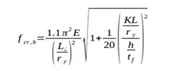
Isolated Footing Design (IS 456-2000)
Footing No.
Group ID
Foundation Geometry
-
-
Length
Width
Thickness
1
1
2.40m
2.40m
0.70m
Footing No.
Footing Reinforcement
Pedestal Reinforcement
-
Bottom Reinforcement(Mz )
Bottom Reinforcement(Mx )
Top Reinforcement(Mz )
Top Reinforcement(Mx )
Main Steel
Trans Steel
1
Ø16 @ 250 mm c/c
Ø16 @ 250 mm c/c
N/A
N/A
14 - Ø12
Ø8 mm @ 175 mm
0.3 m1 m0.7 m0.5 mElevation
1.2 m1.2 m2.4 m2.4 m0.61 mXZPlan
Input Values
Design Type
:
Calculate Dimension with user specified minimums as starting value
Minimum Footing Length - X(Fl)
:
2000.00
mm
Minimum Footing Width - Z (Fw)
:
2000.00
mm
Minimum Footing Thickness(Ft)
:
700.00
mm
Eccentricity along X (Oxd)
:
0.00
mm
Eccentricity along Z (Ozd)
:
0.00
mm
Column Shape
:
Circular
Column Dia
:
0.47
m
Include Pedestal
:
Yes
Pedestal Shape
:
Circular
Pedestal Height (Ph)
:
0.30
m
Pedestal Dia
:
0.61
m
Concrete and Rebar Properties
Unit Weight of Concrete
:
24.00
kN/m3
Strength of Concrete
:
40.00
N/mm2
Yield Strength of Steel
:
500.00
N/mm2
Minimum Bar Size
:
Ø16
Maximum Bar Size
:
Ø32
Pedestal Minimum Bar Size
:
Ø8
Pedestal Maximum Bar Size
:
Ø40
Minimum Bar Spacing
:
100.00
mm
Maximum Bar Spacing
:
450.00
mm
Pedestal Clear Cover (P, CL)
:
50.00
mm
Footing Clear Cover (F, CL)
:
50.00
mm
Unit Weight
:
17.60 kN/m3
Base Value of Soil Bearing Capacity
:
120.00 kPa
Multiplying factor for soil bearing capacity for ultimate loads
:
1.70
Soil Bearing Capacity Type
:
Gross Bearing Capacity
Soil Surcharge
:
0.00 kN/m2
Height of Soil above Footing
:
500.00 mm
Type of Depth
:
Fixed Top
Minimum Percentage of Slab area in Contact for Service Loads
:
0.00
Minimum Percentage of Slab area in Contact for Ultimate Loads
:
0.00
Coefficient of Friction
:
0.50
Factor of Safety Against Sliding
:
1.50
Factor of Safety Against Overturning
:
1.50
Top Reinforcement Option :
Calculate only when foundation is subjected to uplift forces
Concrete Design Option :
Net Pressure(Gross Pressure - Self Weight Pressure)
------------------------------------------------------
Load Combination/s- Service Stress Level
Load Combination Number
Load Combination Title
Load Case Multiplier (a)
Soil Bearing Factor (b)
Self Weight Factor (c)
Code
a - Value specified in the Load Multiplier table
1
EQX+
1.00
1.00
1.00
-
2
EQZ+
1.00
1.00
1.00
-
5
WL(0+CPI)
1.00
1.00
1.00
-
6
WL(0-CPI)
1.00
1.00
1.00
-
7
WL(90+CPI)
1.00
1.00
1.00
-
8
WL(90-CPI)
1.00
1.00
1.00
-
4
LL
1.00
1.00
1.00
-
3
DL
1.00
1.00
1.00
-
Load Combination/s- Strength Level
Load Combination Number
Load Combination Title
Load Case Multiplier (a)
Soil Bearing Factor (b)
Self Weight Factor (c)
Code
a - Value specified in the Load Multiplier table
1
EQX+
1.00
1.00
1.00
-
2
EQZ+
1.00
1.00
1.00
-
5
WL(0+CPI)
1.00
1.00
1.00
-
6
WL(0-CPI)
1.00
1.00
1.00
-
7
WL(90+CPI)
1.00
1.00
1.00
-
8
WL(90-CPI)
1.00
1.00
1.00
-
4
LL
1.00
1.00
1.00
-
3
DL
1.00
1.00
1.00
-
Before consideration of self weight and load multiplier table
Moments are About the center of Column / Pedestal (does not include moments caused by lateral loads)
Applied Loads for Column - Service Stress Level
Load Case Fx Fy Fz Mx Mz
1
1.76
4.06
0.04
0.00
0.00
2
0.01
14.94
12.52
0.00
0.00
5
7.55
16.06
-1.59
0.00
0.00
6
16.96
22.56
0.91
0.00
0.00
7
19.52
62.07
18.03
0.00
0.00
8
0.08
-41.84
-1.85
0.00
0.00
4
-0.27
-7.04
-0.00
0.00
0.00
3
-0.14
-13.65
-0.00
0.00
0.00
Applied Loads for Column - Strength Level
Load Case Fx Fy Fz Mx Mz
1
1.76
4.06
0.04
0.00
0.00
2
0.01
14.94
12.52
0.00
0.00
5
7.55
16.06
-1.59
0.00
0.00
6
16.96
22.56
0.91
0.00
0.00
7
19.52
62.07
18.03
0.00
0.00
8
0.08
-41.84
-1.85
0.00
0.00
4
-0.27
-7.04
-0.00
0.00
0.00
3
-0.14
-13.65
-0.00
0.00
0.00
------------------------------------------------------
Initial Length (Lo )
=
2.00
m
Initial Width (Wo )
=
2.00
m
Area from initial length and width, Ao
=
Lo×Wo
=
4.00
m2
Min. area required from bearing pressure, Amin
=
Pqmax
=
1.20
m2
Note: Amin is an initial estimation.
P = Vertical load from column + selfweight of footing + weight of soil.
qmax = Respective Factored Bearing Capacity.
Length (L2 ) =
2.40
m
Governing Load Case :
# 8
Width (W2 ) =
2.40
m
Governing Load Case :
# 8
Depth (D2 ) =
0.70
m
Area (A2 ) =
5.76
m2
Depth is governed by Ultimate Load Case
(Service check is performed with footing thickness requirements from concrete check)
Final Pedestal Height =
0.30
m
Final Soil Height =
0.50
m
Weight of the footing + pedestal (if any)
=
98.90
kN
Weight of the soil above the footing (dry)
=
48.12
kN
Uplift force due to buoyancy
=
0.00
kN
Effect due to adhesion
=
0.00
kN
------------------------------------------------------
Load Case
Pressure at top left corner
Pressure at top right corner
Pressure at bottom right corner
Pressure at bottom left corner
Area of footing in uplift (Au )2 )
Gross Bearing Capacity
8
33.5595 33.6293
32.0186
31.9488
0.00
120.0000
8
33.5595
33.6293 32.0186
31.9488
0.00
120.0000
8
33.5595
33.6293
32.0186 31.9488
0.00
120.0000
8
33.5595
33.6293
32.0186
31.9488 0.00
120.0000
If Au is zero, there is no uplift and no pressure adjustment is necessary. Otherwise, to account for uplift, areas of negative pressure will be set to zero and the pressure will be redistributed to remaining corners.
Summary of adjusted Gross Pressures at Four Corners
Load Case
Pressure at
Pressure at
Pressure at
Pressure at
Gross Bearing Capacity
8
33.5595 33.6293
32.0186
31.9488
120.0000
8
33.5595
33.6293 32.0186
31.9488
120.0000
8
33.5595
33.6293
32.0186 31.9488
120.0000
8
33.5595
33.6293
32.0186
31.9488 120.0000
Details of Out-of-Contact Area
Governing load case
=
N/A
Plan area of footing
=
5.76
sq.m
Area not in contact with soil =
=
0.00
sq.m
% of total area not in contact
=
0.00%
------------------------------------------------------
0.3 m1 m0.7 m0.5 m.Frictional ForceSliding ForceOTM
-
Factor of safety against sliding
Factor of safety against overturning
Load Case No.
Along X-Direction
Along Z-Direction
Resultant
Required FOS
About X-Direction
About Z-Direction
Required FOS
1
40.53
N/A
40.52
1.50
N/A
96.82
1.50
2
N/A
5.28
5.28
1.50
12.60
N/A
1.50
5
8.68
41.10
8.49
1.50
98.17
20.72
1.50
6
3.67
68.48
3.66
1.50
163.57
8.76
1.50
7
2.18
2.36
1.60
1.50
5.63
5.20
1.50
8
1179.95
51.14
51.09
1.50
122.14
N/A
1.50
4
283.97
N/A
283.96
1.50
N/A
678.27
1.50
3
570.73
N/A
570.71
1.50
N/A
1363.21
1.50
Critical Load Case And The Governing Factor Of Safety For Overturning and Sliding X Direction
Critical Load Case for Sliding along X-Direction
:
7
Governing Disturbing Force
:
19.52
kN
Governing Restoring Force
:
42.48
kN
Minimum Sliding Ratio for the Critical Load Case
:
2.18
Critical Load Case for Overturning About X-Direction
:
7
Governing Overturning Moment
:
18.12
kNm
Governing Resisting Moment
:
101.94
kNm
Minimum Overturning Ratio for the Critical Load Case
:
5.63
Critical Load Case And The Governing Factor Of Safety For Overturning and Sliding Z Direction
Critical Load Case for Sliding along Z-Direction
:
7
Governing Disturbing Force
:
18.03
kN
Governing Restoring Force
:
42.48
kN
Minimum Sliding Ratio for the Critical Load Case
:
2.36
Critical Load Case for Overturning About Z-Direction
:
7
Governing Overturning Moment
:
-19.62
kNm
Governing Resisting Moment :
:
101.94
kNm
Minimum Overturning Ratio for the Critical Load Case
:
5.20
Critical Load Case And The Governing Factor Of Safety For Sliding Along Resultant Direction
Critical Load Case for Sliding along Resultant Direction :
:
7
Governing Disturbing Force
:
26.58
kN
Governing Restoring Force
:
42.48
kN
Minimum Sliding Ratio for the Critical Load Case
:
1.60
------------------------------------------------------
Top Reinforcement Design Requirement
Top Reinforcement needs to be provided because of resultant negative pressure coming from net pressure calculations for bending.
Ultimate Gross Pressures
The base pressures reported in this table and the area of footing in contact include the effect of buoyancy (if any).
Load Case / Load Combination ID
Pressure at top left corner
Pressure at top right corner
Pressure at bottom right corner
Pressure at bottom left corner
Gross Factored Bearing Capacity For Ultimate Load Case
Area of footing in Contact with soil (Au )2 )
1
24.0337
25.5719
25.6063
24.0681
204.0000
5.76
2
17.4668
17.4760
28.3955
28.3863
204.0000
5.76
5
20.1388
26.7222
25.3327
18.7493
204.0000
5.76
6
13.8132
28.6091
29.4017
14.6058
204.0000
5.76
7
0.0000
15.3955
31.1412
14.0972
204.0000
5.73
8
33.5595 33.6293 32.0186 31.9488 204.0000
5.76
4
26.8658
26.6292
26.6276
26.8642
204.0000
5.76
3
27.9556
27.8329
27.8318
27.9546
204.0000
5.76
Minimum Required Contact Area for Ultimate Loads
:
0.00
m2
Actual Area in Contact for all ultimate load cases exceeds the minimum required. Hence Safe
Maximum Corner Pressure from all ultimate load cases is less than the allowable. Hence Safe
Check Trial Depth against moment (About Z Axis)
Critical Load Case = #8
Effective Depth
=
D-(cc+1.5 × db)
=
0.63
m
Governing moment (Mu )
=
=
7.36
kNm
As Per IS 456 2000 ANNEX G G-1.1C
Limiting Factor1 (Kumax )
=
700[1100+(0.87 × fy )]
=
0.46
Limiting Factor2 (Rumax )
=
0.36×fck×kumax×(1-0.42×kumax)
=
5309.03
kN/m2
Limiting Moment Of Resistance (Mumax )
=
Rumax×B×d2
=
4993.07
kNm
Mu <= Mumax hence, safe
Check Trial Depth against moment (About X Axis)
Critical Load Case = #8
Effective Depth
=
D-(cc+1.5 × db)
=
0.63
m
Governing moment (Mu )
=
=
7.92
kNm
As Per IS 456 2000 ANNEX G G-1.1C
Limiting Factor1 (Kumax )
=
700[1100+(0.87×fy )]
=
0.46
Limiting Factor2 (Rumax )
=
0.36×fck×kumax×(1-0.42×kumax)
=
5309.03
kN/m2
Limiting Moment Of Resistance (Mumax )
=
Rumax × B × d2
=
4993.07
kNm
Mu <= Mumax hence, safe
------------------------------------------------------
(Shear Plane Parallel to Global X Axis)
1.2 m1.2 m0.265 m0.265 mPlanXZ
Critical Load Case = # 8
Distance of critical section from top left corner along Z, DZ
=
0.27
m
Shear Force(S)
=
5.46
kN
Shear Stress(Tv )
=
3.63
kN/m2
Percentage Of Steel(Pt )
=
0.1338
As Per IS 456 2000 Clause 40 Table 19
Shear Strength Of Concrete(Tc )
=
300.00
kN/m2
Shear Enhancement Factor (if considered) is applied to (Tc ), as per IS456 -2000 Clause No 40.5.1 and Fig 24
Tv < Tc hence, safe
(Shear Plane Parallel to Global Z Axis)
1.2 m1.2 m0.265 m0.265 mPlanXZ
Critical Load Case = # 8
Distance of critical section from top left corner along X, DX
=
0.27
m
Shear Force(S)
=
5.02
kN
Shear Stress(Tv )
=
3.34
kN/m2
Percentage Of Steel(Pt )
=
0.13
As Per IS 456 2000 Clause 40 Table 19
Shear Strength Of Concrete(Tc )
=
300.00
kN/m2
Shear Enhancement Factor (if considered) is applied to (Tc ), as per IS456 -2000 Clause No 40.5.1 and Fig 24
Tv < Tc hence, safe
Critical Load Case = #8
Shear Force(S)
=
36.36
kN
Shear Stress(Tv )
=
16.53
kN/m2
As Per IS 456 2000 Clause 31.6.3.1
Ks
=
min[0.5+β,1]
=
1.00
Shear Strength(Tc )
=
0.25×fck
=
1581.14
kN/m2
------------------------------------------------------
Reinforcement Calculation
Calculation of Maximum Bar Size
Bar diameter corresponding to max bar size (db )
=
20
mm
As Per IS 456 2000 Clause 26.2.1
Development Length(ld )
=
db×0.87×fy4×τbd
=
0.72
m
Available Development Length(ldb )
=
(B-b)2-cc
=
0.85
m
ldb >=ld hence, safe
Bar diameter corresponding to max bar size(db )
=
20
mm
As Per IS 456 2000 Clause 26.2.1
Development Length(ld )
=
db×0.87×fy4×τbd
=
0.72
m
Available Development Length(ldb )
=
(H-h)2-cc
=
0.85
m
ldb >=ld hence, safe
Design For Bottom Reinforcement Parallel to Z Axis
For moment About X Axis (Mx )
As Per IS 456 2000 Clause 26.5.2.1
Critical Load Case = #8
Minimum Area of Steel (Astmin )
=
2016
mm2
Calculated Area of Steel (Ast )
=
2016
mm2
Note - "Area of Steel required" reported here is the larger value between the calculated area of steel and minimum steel required as per code stipulations
Provided Area of Steel (Ast,Provided )
=
2011
mm2
Ast,Provided >= Astmin
Hence OK.
Selected bar Size (db )
=
Ø16
Minimum spacing allowed (Smin )
=
100.00
mm
Selected spacing (S)
=
253.78
mm
Smin <= S <= Smax and selected bar size < selected maximum bar size. Hence OK.
Based on spacing reinforcement increment; provided reinforcement is
Design For Bottom Reinforcement Parallel to X Axis
For moment About Z Axis (Mz )
As Per IS 456 2000 Clause 26.5.2.1
Critical Load Case = #8
Minimum Area of Steel (Astmin )
=
2016
mm2
Calculated Area of Steel (Ast )
=
2016
mm2
Note - "Area of Steel required" reported here is the larger value between the calculated area of steel and minimum steel required as per code stipulations
Provided Area of Steel (Ast,Provided )
=
2011
mm2
Ast,Provided >= Astmin
Hence OK.
Selected bar Size (db )
=
Ø16
Minimum spacing allowed (Smin )
=
100.00
mm
Selected spacing (S)
=
253.78
mm
Smin <= S <= Smax and selected bar size < selected maximum bar size. Hence OK.
Based on spacing reinforcement increment; provided reinforcement is
Pedestal at Support No.
Axial Capacity Ratio, Critical Load Case, Location
Flexural Capacity Ratio
% of Main Steel
Main Reinforcement
Links
1
0.01, 8, Bottom
0.17
0.54
14-T12
8 @ 175mm
Pedestal Shape
=
Circular
Pedestal Diameter
=
609.60
mm
Longitudinal Reinforcement Details
Area of Longitudinal Bars
=
1583.40
sq.mm
Number of Bars and Bar Dia
=
14-T12
Longitudinal Steel Percentage
=
0.54
Flexure - Governing Load Case Details
Governing Load Case Number
=
7
Critical Location
=
Bottom
Axial load
=
-55.03
kN
Moment about X axis
=
18.12
kNm
Moment about Z axis
=
-19.62
kNm
Resultant moment
=
26.70
kNm
Moment Capacity
=
154.69
kNm
Angle of inclination of Neutral Axis with respect to local Z
=
42.73 degrees
Serial No.
P
M
1
-688.78
0.00
2
-681.48
2.10
3
-614.23
21.44
4
-387.31
79.27
5
-112.24
142.68
6
159.98
199.81
7
445.32
250.86
8
733.86
295.88
9
1032.88
334.05
10
1186.51
350.31
11
1340.23
364.52
12
1493.98
376.85
13
1650.04
387.07
14
1812.08
394.89
15
1974.41
400.74
16
2136.04
404.58
17
2298.19
406.40
18
2463.96
405.59
19
2628.76
403.01
20
2795.57
397.92
21
2958.96
391.48
22
3118.49
383.62
23
3274.74
374.51
24
3428.11
364.10
25
3578.44
352.36
26
3725.47
339.43
27
3869.27
325.36
28
4145.80
294.22
29
4406.06
259.79
30
4646.25
223.49
31
4861.85
187.41
32
4995.50
161.06
33
5101.14
140.13
34
5186.20
123.22
35
5255.82
109.36
36
5361.93
88.15
37
5437.91
72.81
38
5494.47
61.34
39
5537.81
52.53
40
5571.82
45.59
41
5599.05
40.01
42
5621.24
35.45
43
5639.58
31.67
44
5667.94
25.80
45
5688.47
21.50
46
5703.49
18.24
47
5715.13
15.70
48
5724.35
13.67
49
5825.71
0.00
Moment [kNm]Axial Load [kN]070140210280350406.403637-100001000ϕM (42.73 deg) (kNm)
Shear - Governing Load Case Details
Critical Load Case for Shear Along Resultant Direction
=
7
Shear Force Along Resultant Direction
=
26.58
kN
Transverse Stirrups Details
Crack Width Calculation (for Mz)
Modulus of Elasticity of Concrete(Ec )
=
31622776.60
kN/m2
Clause No. 6.2.3.1
Modulus of Elasticity of Steel(Es )
=
200000000.00
kN/m2
Annexure F
Depth of Neutral Axis(Xu )
=
0.30
m
Annexure G, Clause No. G-1.1.a
Effective MOI(Ieff )
=
23054910909.11
mm4
Average Steel Strain at Considered Level(Ɛm )
=
0.00 X 10⁻⁵
Distance from Nearest Tension Rod (acr )
=
0.14
m
Crack Width (Wcr )
=
0.00
mm
Annexure F
From IS 456-2000 Clause No. 35.3.2
Section is uncracked.
Crack Width Calculation (for Mx)
Modulus of Elasticity of Concrete(Ec )
=
31622776.60
kN/m2
Clause No. 6.2.3.1
Modulus of Elasticity of Steel(Es )
=
200000000.00
kN/m2
Annexure F
Depth of Neutral Axis(Xu )
=
0.30
m
Annexure G, Clause No. G-1.1.a
Effective MOI(Ieff )
=
23054910909.11
mm4
Average Steel Strain at Considered Level(Ɛm )
=
0.00
X 10-5
Distance from Nearest Tension Rod (acr )
=
0.14
m
Crack Width (Wcr )
=
0.00
mm
Annexure F
From IS 456-2000 Clause No. 35.3.2
Section is uncracked.
------------------------------------------------------
1.2 m1.2 mPlan2.4 m2.4 m0.61 mXZ0.3 m1 m0.7 m0.5 mElevationFoundationPedestalDimensions (m)ReinforcementLBD2.4 m2.4 m0.7 mlbh0.61 m0.61 m0.3 mAstX(T)AstZ(T)AstX(B)AstZ(B)N/AN/A10 - 16 mm10 - 16 mmMain ReinforcementTrans Reinforcement12 mm - 148 mm @ 175 mm1.2 m1.2 mTOP N/ATOP N/ABOTTOM 10 - 16 mmBOTTOM 10 - 16 mmPlan
Title
Design of Base Plate
Step 1
Strength of concrete
fcu
=
50
N/mm2
Yield strength of steel
fy
=
500
N/mm2
Material factor
γm
=
1.1
kN
Factored load
=
2000
kN
Step 2
Steel column section
Thickness of flange
T
=
14.2
mm
Step 3
Area required
Bearing strength of concrete
=
0.4 fcu
=
20
N/mm2
Area required
=
100000
mm2
Let size of plate
Bplate
=
350
mm
Dplate
=
350
mm
Area of plate
=
122500
mm2
Let projection on each side
a = b
=
25
mm
w
=
16.33
N/mm2
Cl 7.4.3.1
Thickness of slab base
ts
=
6.3
mm
<
14.20
mm
So use base plate of size 350mm x 350mm x 12mm
Title
Design of Column
Height of column
h
=
9
m
Yield strength
fy
=
500
N/mm2
Elastic modulus
E
=
300000
N/mm2
Material factor
γm
=
1.1
Step 1
Section classification
Properties of selected section
ISHB
400
A
10466
mm2
h
400
mm
d
374.6
B
250
mm
t
10.6
mm
T
12.7
mm
rx
166.1
mm
ry
51.6
mm
Zp
cm3
Flange criterion
b/T
=
9.84
Web criterion
d/t
=
35.34
Ɛ
=
0.71
b/T
>
7.42462
d/t
>
29.6985
The section is classified as COMPACT
Step 2
Effective Length
T7.5
As both ends pin-jointed
KLx
=
9.00
m
KLy
=
9.00
m
KLz
=
9.00
m
Slenderness ratio
KLx/rx
=
54.18
KLy/ry
=
174.42
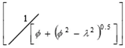
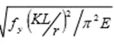
Non-dimensional effective slenderness ratio
Cl 7.1.2.1
λ
=
=
2.268
Step 3
To calculate φ
φ = 0.5[1+α(λ-0.2)+λ2 ]
h/bf
=
1.60
>
1.2
T
=
12.7
mm
T 7.1
so, buckling class
=
b
α
=
0.34
φ
=
3.42
Step 4
Calculation of χ
χ =
χ
=
0.167
N/mm2
Step 5
Calculation of fcd
fcd
=
χfy/γm
=
75.93
Step 6
Factored Axial Load
Pd
=
Afcd
=
794.665
kN
Title
Design of Rafter
Span of I beam
=
5
m
Dead Load
=
12
kN/m
Imposed Load
=
28
kN/m
Length of bearing
=
150
mm
Yield strength
=
500
N/mm2
40
5
Step 1
Design load calculation
Factored Load
=
60.00
kN/m
Factored bending moment
=
187.50
kNm
Step 2
Section modulus - Required
Z reqd
=
412500.0
mm3
=
412.50
cm3
Step 3
Section classification
Properties of selected section
ISMB
250
A
475.5
mm2
D
250
mm
B
125
mm
t
6.9
mm
T
12.5
mm
Izz
5131.6
cm4
Iyy
344.5
cm4
Zp
459.76
cm3
Flange criterion
B/2T
=
5
Web criterion
(D-2T)/t
=
32.61
Ɛ
=
0.70711
B/2T
<
9.4
(D-2T)/t
<
59.3263
The section is classified as PLASTIC
Step 3
Moment of resistance of the cross section
Moment
Md
=
(Zpxfy)/γm
Md
=
208.982
kNm
>
187.50
Hence section ISMB 250 is adequate for flexure
Step 4
Shear resistance of the cross section
Shear capacity
Vc
=
0.6fyAv/γm
Av
=
1725
mm2
Vc
=
470.45
kN
Factored shear
V
=
150.00
kN
V/Vc
=
0.32
<
0.6
Step 5
Check for Web Buckling
Slenderness ratio of web
=
2.5d/t
d
=
225
=
70.33
Design compressive stress
fc
=
203
N/mm2
Pw
=
385193
=
385.19
kN
>
150.00
Hence web is safe against shear buckling
Step 6
Check for web crippling at support
Root radius of ISMB 250
R
=
13
mm
tf + R
=
25.5
mm
Dispersion length
n2
=
63.75
mm
Pcrip
=
641250
N
=
641.25
kN
>
150.00
Hence section adequate for web crippling
Step 7
Check for serviceability - Deflection
Design load
=
40
kN/m
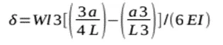
Deflection
δ
=
31.72
mm
Allowable deflection
=
25
mm
Hence serviceability is satisfied
Week 9
For maximum reaction on girder, the moving load should be as close to the gantry as possible
240 kN
200 kN
A
1
14
B
15 m
hence , greater section is adopted for this design as it failing