Project 2
AIM:Design and Develop a simulink model to understand Energy analysis of EVs on different driving cycles
BLOCK USED: Electrical vehicle subsystem,Energy analysis subsystem,FTP75drivecycle
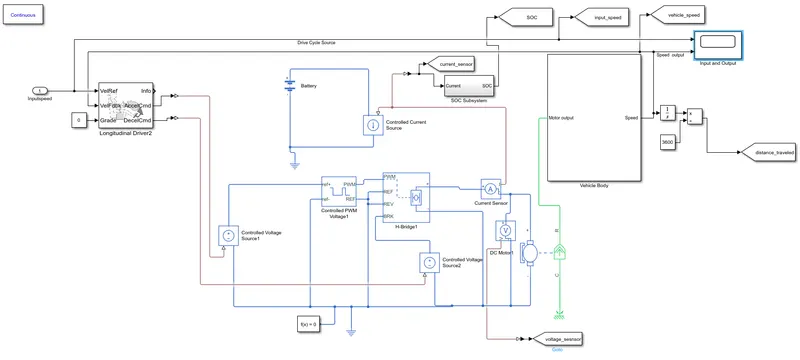
Electrical vehicle subsystem model is designed as below:
Working:
The Drive Cycle Source block generates a FTP75 longitudinal drive cycle and give specified vehicle longitudinal speed, .It Produce realistic velocity and shift references for closed loop acceleration and braking commands for vehicle control according to FTP75 drive cycle its value varies from 0 to 1.This acceleration and brak commands are given to simulink to ps converter ,this block converts those signals to physical system signalThis signal is given to physically controlled voltage source,It produces voltage output according to the physical signal input,these output are also varies between zero to 1The output of controlled voltage source1 goes to controlled PWM voltage and output of controlled voltage source goes to brak input of H bridgeIn controlled PWM voltage we set mininum input voltage 0 and maximum input voltage 1 because the input varies between 0 and 1 .It give output according to input signalsThese output values is fed to a H bridge If the input signal has a value greater than the Enable threshold voltage parameter value 2.5V the H-Bridge block output is on and has a value equal to the value of the Output voltage amplitude 800V. If it has a value less than the Enable threshold voltage parameter value, the block maintains the load circuit using freewheeling diode.The Output of H bridge is connected to dc motor the motor rotates according to the voltage output fom h bridge.The current flowing through H bridge given goes to controlled current source and it controled current in battery circuit and give SOC% accordinglyThe transmission is happening in dc motor here the electrical energy is converting to mechanical energy.The mechanical outputfrom the motor is given to vehical body subsytem ,It first go to a simple gear with tooth ratio 10,So it multiply torque to tentimes and given to the axle ,the inertia block provide proper inertia to tire to move.The resulting traction motion developed by tires is given to vehicle body through port H. Then physical signal output ports NF and NR goes to front and rear tires thses are normal wheel forces, which moves the tires.Headwindspeed and road inclination values are also given The vehicle body gives the Speed output according to the input given to it.
For modeling of energy analysis subsystem We consider:
Rolling Resistance Force= μrr*m*g
Frontal Area=0.85*Width*Height
Airdrag force=0.5*ρ*A*Cd*V^2
Hill climbingforce=m*g*sin(Ψ)
Accelerational force=m*a
Acceleration Power=0.5*(m*Vf^2)
Power=Force*V
Total propulsion power=Prr+Pad+Phc+Pac
We can find tractive energy by integrating Tractive power
For designing we have taken electric vehicle mass=1400kg,Coefficient of rolling resistance=0.005,width in m=1.8 ,height in m=1,Frontal are=1.53m^2=Drag coefficient 0.19,Angle of inclination =0.01rad,
We can find different constant gain for simulation using above values
Accelerational force=m*a
=1400*a
Airdrag force=0.5*ρ*A*Cd*V^2
=0.182*v^2
Rolling Resistance Force= μrr*m*g
=1400*9.8*0.005
=68.6N
Grade force=mgsin(angle of inclination)=137N
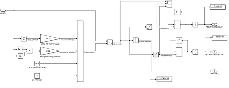
Then modeled energy analysis subsystem as follows
Working:
Here total tractive force is calculated using formula,Tractive force=Accelerational force+ Rolling Resistance Force+ Hill climbingforce+Airdrag force This total tractive force vis multiplied with speed to find propulsion power,then a integrator block is given to calculate total tractive energy.Here we used saturation blocks for separating positive and negative energy,Positive energy is the energy used for acceleration negative energy is the energy used for decceleration.
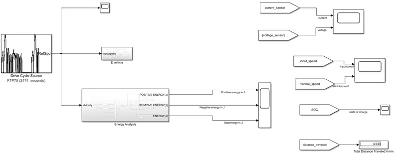
Over all model:
Results:
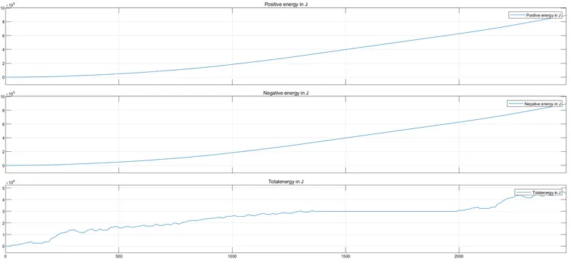
- The output of Positive energy ,Negative energy and total energy is shown below
- At the end of the cycle total energy value is 4.54*10^6J for given FTP75
- Input and output speed variation is shown below we can understand that vehicle follow the same speed as given input
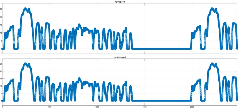
- State of charge output is shown below,Battery is discharging as time increases,Initially battery is fully charged and battery got discharged with time and 78% battery is remaining
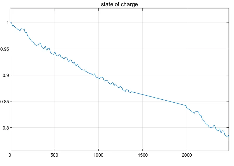
- Total distance travelled for given FTP75 Drive cycle=4.943km
Conclusion:
Created matlab model for calculating tractive energy of electric vehicle with FTP75 drive cycle as input and average speed of 100m/s with PI controler type with proportional gain 1000 and integral gain 100 .we used battery of 500V and dc motor of power rating 1500kW,regenerative breaking is enabled ,The distance traveled by the car is measured ,The car cover 4.943km in 2747 seconds ,78% of battey is remaining The total tractive energy at the end of this drive cycle is 4.54*10^6J