Project 2
Aim :
To Run simulations, change the threshold create plots and measure current and hydrogen consumption. Specify the outputs. How to run the model.
Answer:
Simulink model :
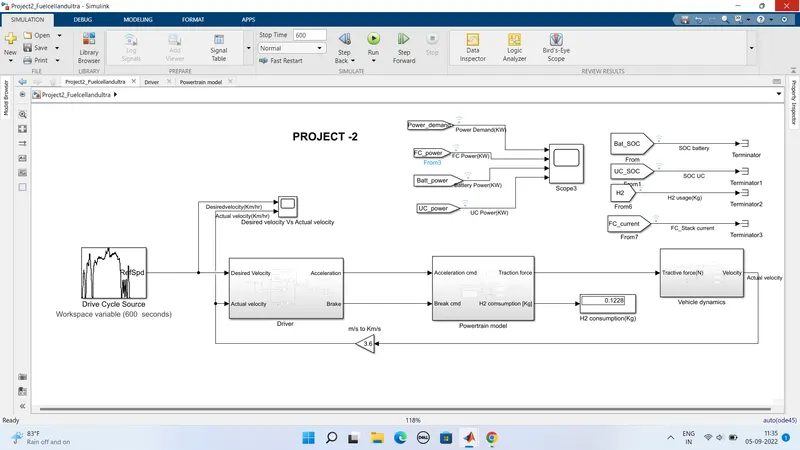
From the above simulink model we can obsereve that it as no of susytems they are
1) Drive cycle source
It gives Desired velocity as output
2) Driver subsystem
It gives Desired velocity and Actual velocity Inputs and Acceleration and brake commands Outputs
3) Power train model subsystem
It gives Acceleration and brake commands Inputs Tractive force Output
This subsystem consist of
- Acceleration or Brake to Torque request subsystem
- Torque request to power output subsystem
- Torque out to Traction force subsystem.
- EMS subsystem
- Fuel Cell model , H2 consumption,O2 consumption,FC current,FC Voltage from FC Power request as input
- Ultracapacitor model ,UC Current,UC OCV,UC SOC,UC Charge from UC Power request as input
- Battery model,Battery current, voltage, Battery SOC from Battery Power request as input.
4) Vehicle dynamics sub system
It gives The Tractive force Input Actual velocity Output
It consist of following systems
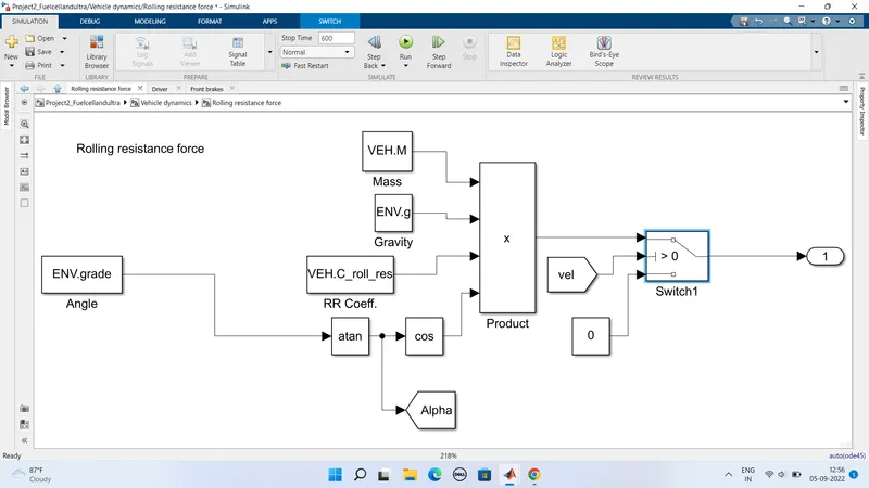
- Rolling resistance force subsystem.
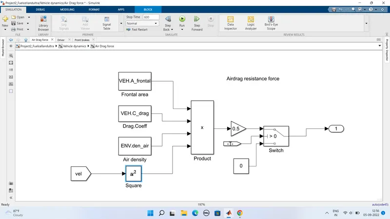
- Airdrag resistance force subsystem.
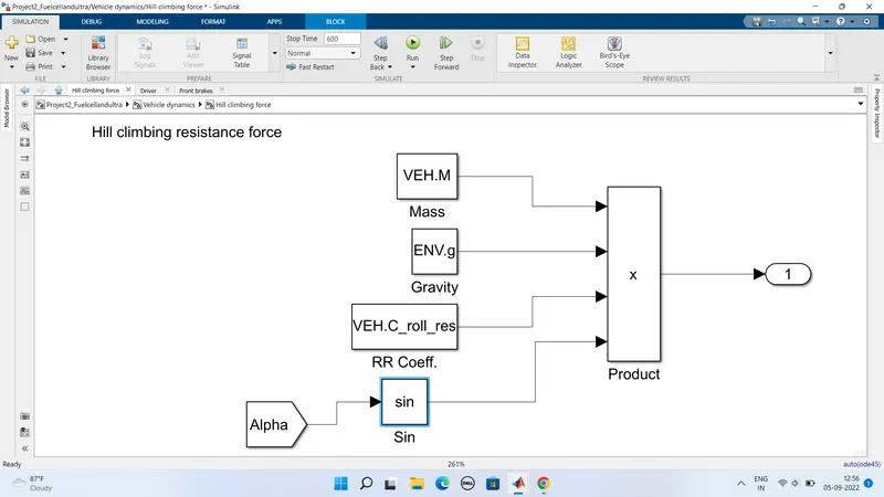
- Hill climbing force subsystem.
1) Drive cycle source:
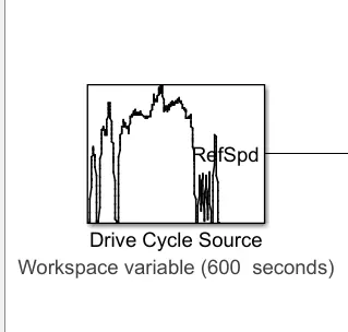
- Here in this model The drive cycle data of US06 is given to the Drive cycle source block
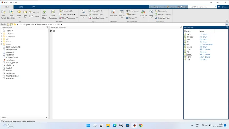
- The US06 drive cycle data file is created and loaded in base workspace area
- As the drive cycle time is for duration 600 secs so here we have to set the stop time as 600 Sec
2) Driver subsystem :-
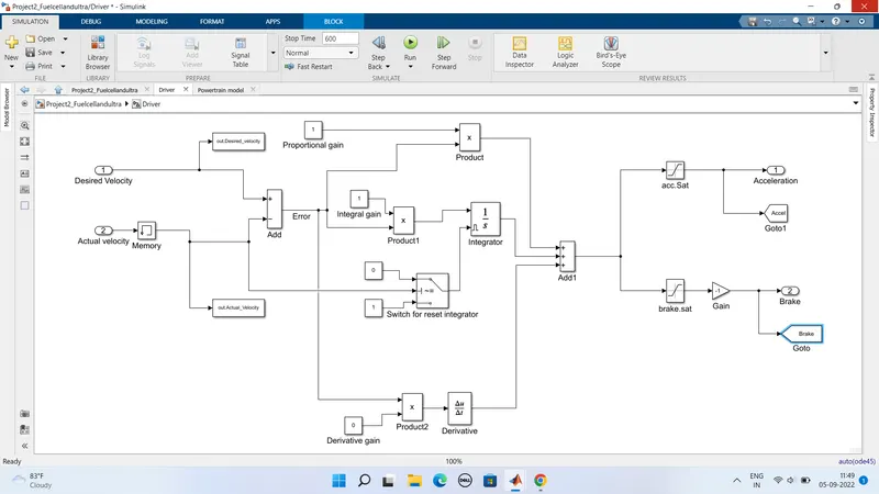
- Here in this block the inputs are Desired velocity from drive cycle source and Actual velocity as feedback from vehicle dynamics subsystem
- So The outputs of this subsystem are acceleration and brake commands
- Here we Initially the Desired velocity is subtracted from actual vehicle velocity and it creats a error difference in velocity output
- So by This error output is feeded as PID outputs and added to get final acceleration or brake command outputs
- So now The error is multiplied with a proportion gain value to perform proportional operation output
- Now next step The error is multiplied with an integral gain value and given to an integrator block to perform integral operation
- Now A switch is to reset the integrator is created as when the velocity of vehicle comes to 0 the integrator gets reset to perform its operation again from initial stage
- This actionuseful to correct the integral error values preventing from integral wind up condition.
- Now Again error is multiplied with a derivative gain and given to a derivative block to perform derivative operation
- Now These actions are considered as a PID controlling of vehicle velocity.
- Atlast All three outputs from PId are added with a ADD block to get final acceleration or brake command outputs
- So now A saturation block of range 0 to 1 given for acceleration command and saturation of 0 to -1 multiplied with -1 given for brake command to consider brake command also in positive values
- But While acceleration is in progress brake is in off state and vise versa
- Here Both acceleration and brake will not occure in same time
3) Power train model subsystem :
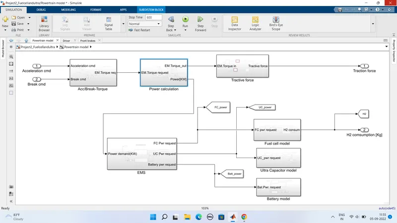
- Here in This subsystem it consist of mainly inputs of acceleration command and brake
- So The output of this subsystem are Traction force which will be feeded as input to vehicle dynamics subsystem
- Here This subsystem consist of various subsystems namely accelerationor brake command to torque power calculation traction force EMS FC model UC mode and battery model
- So Initially the acceleration and brake commands are converted to motor torque request as output from ACCeleration Brake Torque subsystem.
- Then this motor torque request compared with electric motor angular velocity and giving output as Torque output of motor and power required for producing this motor torque is calculated
- Now From this motor torque output taken as input overall tractive force is calculated from Tractive force subsystem.
- So This Tractive force is given as output from overall powertrain block.
- Then The total power calculated Power request from Power calculation subsystem is feeded into Energy Management Startegy subsystem to produce fuel cell power request Ultracapacitor power request and battery power request.
- So now EMS is used to create power sharing requests to FC UC and Batery models.
- Now According to their power requests energy is drained or charged from these three types of energy sources.
- So These power requests are given as inputs to respected FC model UC model and Battery model for calculating their current SOC and voltage values
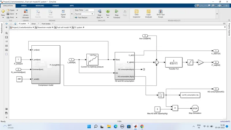
- So now The fuel H2 consumption is calculated from Fuel cell model subsystem
Acceleration or Brake Torque subsystem:
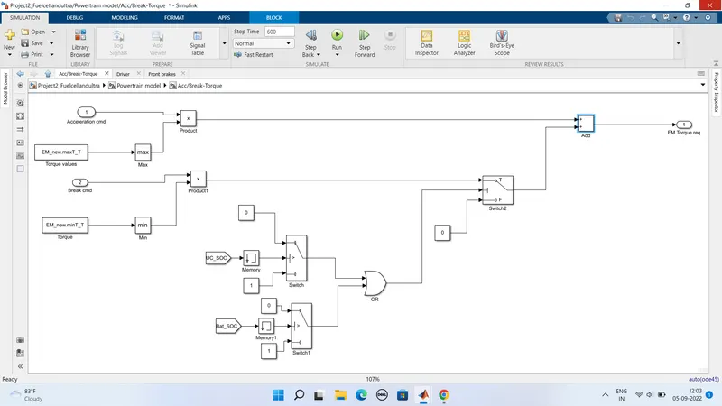
- In this subsystem the inputs are acceleration and brake commands and output is EM Torque request
Power calculation:
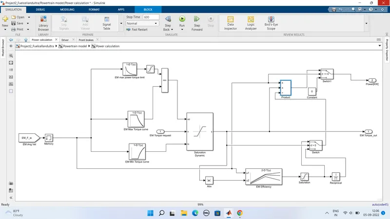
Here In this subsystem the EM Torque request from ACC or Brake Torque subsystem as input and output as motor torque output based on the motor angular velocity
Tractive force subsystem ;
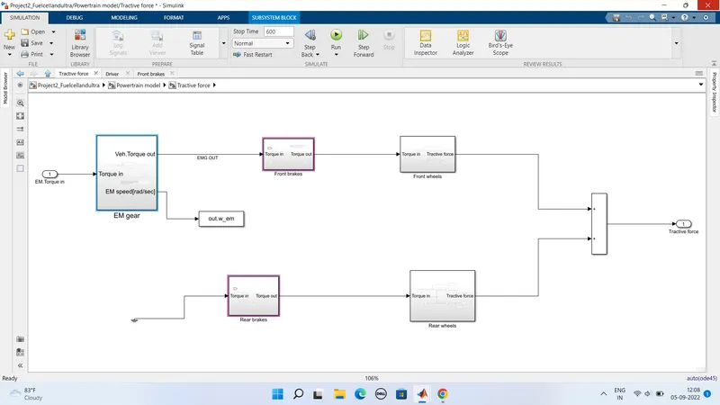
It as different subsystems
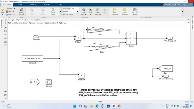
- EM gear
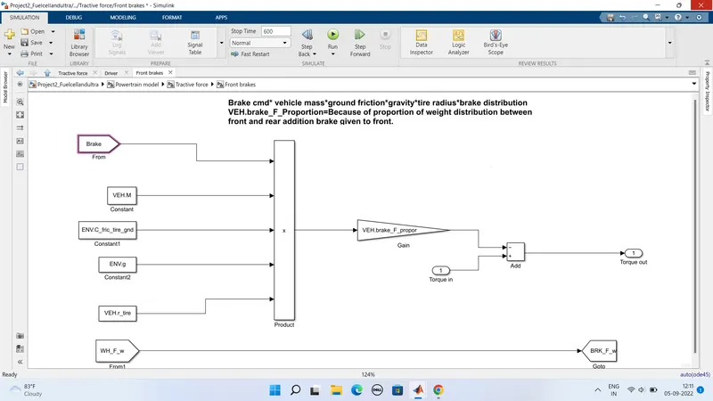
- Front brakes
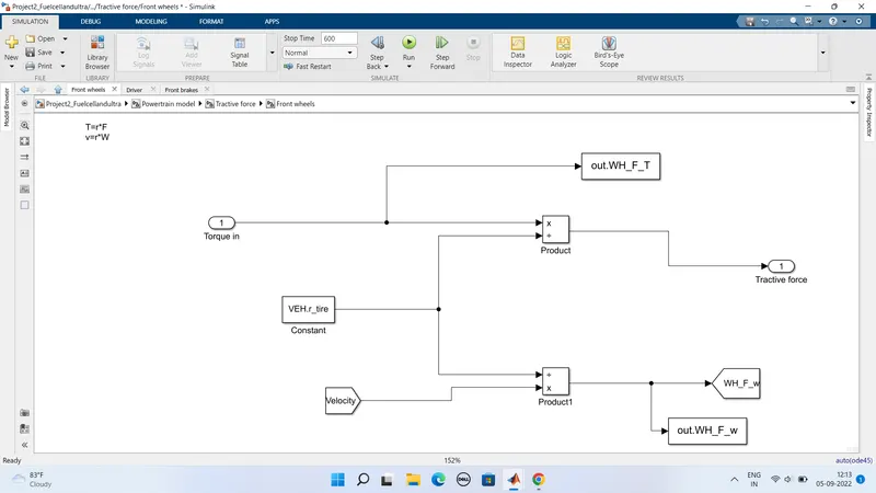
- Front wheels
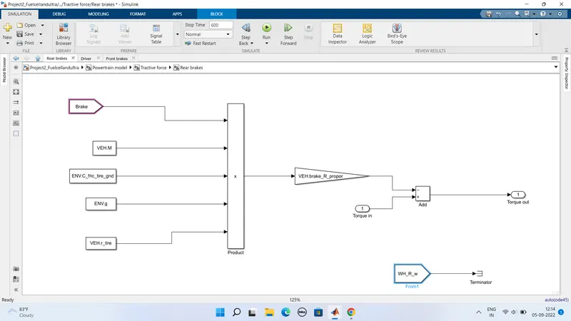
- Rear brakes
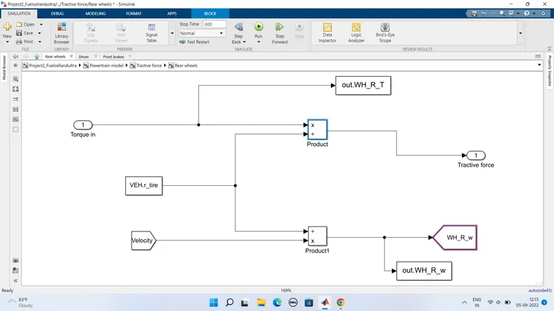
- Rear wheels
EM gear:
Front brakes:
Front wheels:
Rear brakes:
Rear wheels:
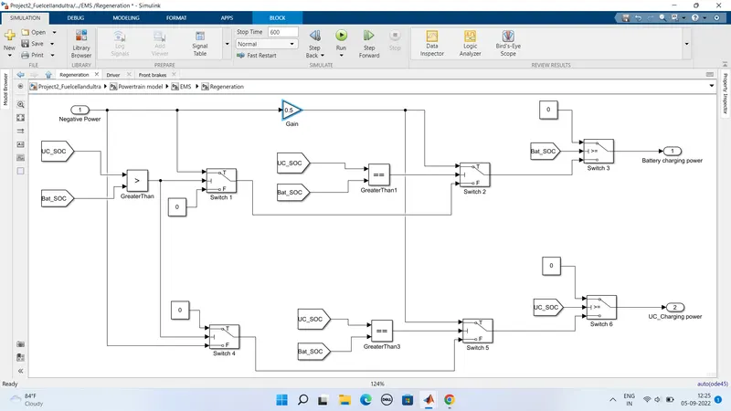
Energy Management System:
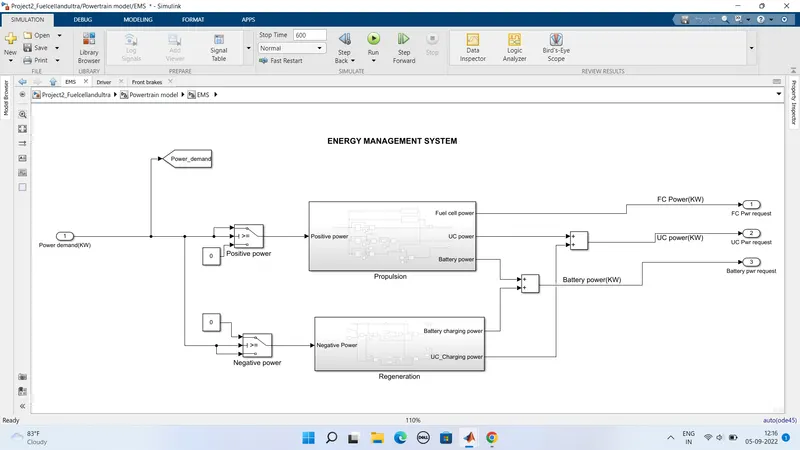
In this subsystem we have seperated the power request power demand from power calculation subsystem as positive power request Propulsion and negative power request Regeneration
Proplsion subsystem:
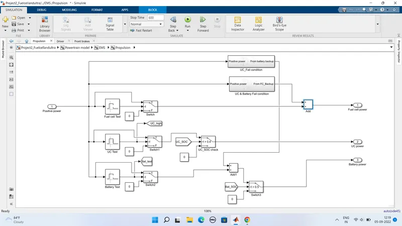
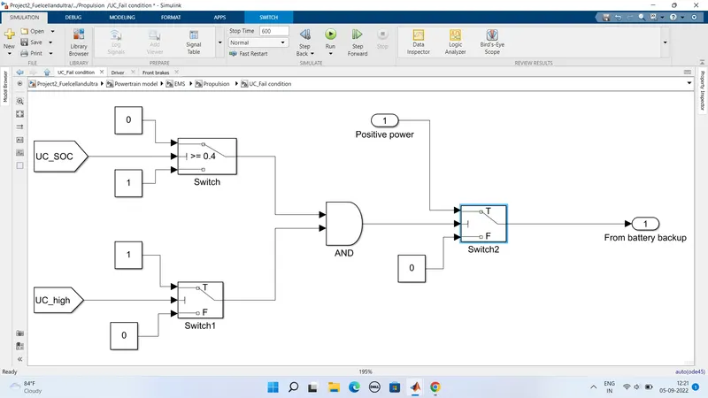
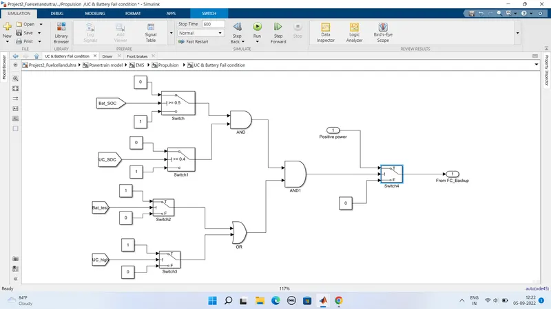
It as mainly two conditions they are
UC_fail condition
UC & Battery fail condtion
Regenerative subsystem:
Fuel cell(FC) model:
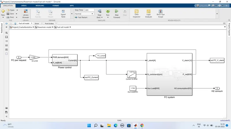
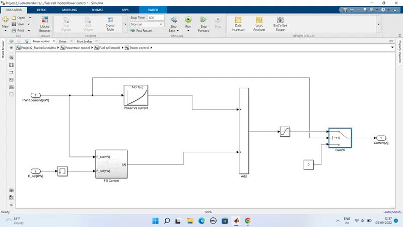
It as again two subsystems 1) Power control 2) FC_system
FC system:-
Ultracapacitor model:
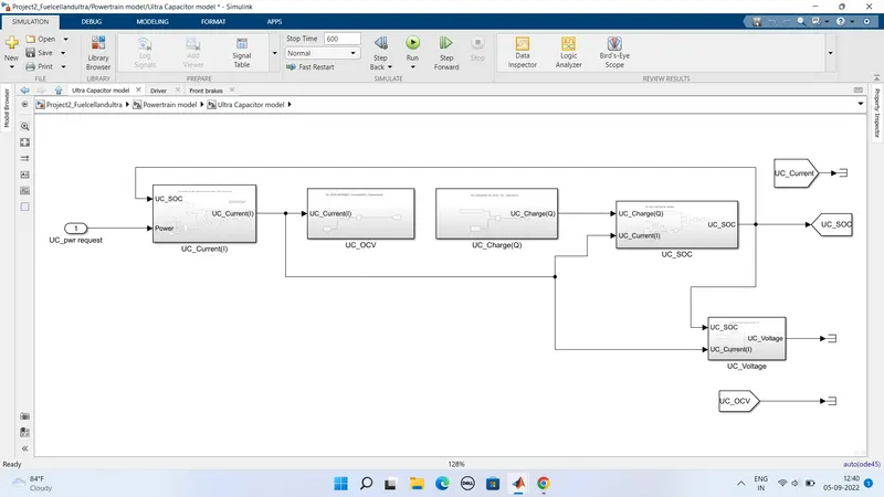
Here From this subsystem we will get the results of UC SOC UC voltage and UC current values.
This subsystem consist of different subsystems they are
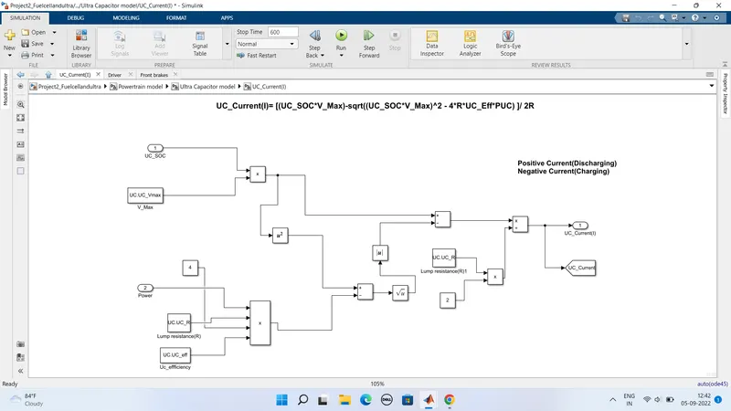
- UC_Current
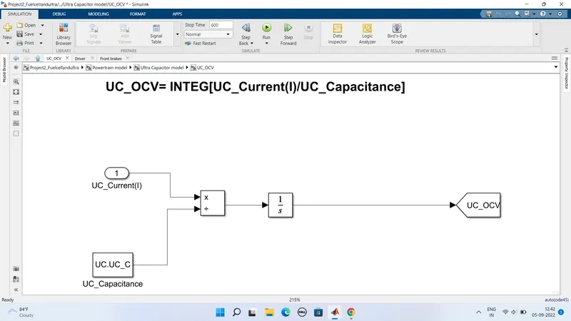
- UC_OCV
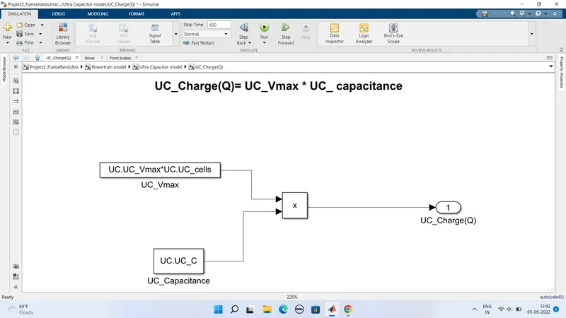
- UC_Charge
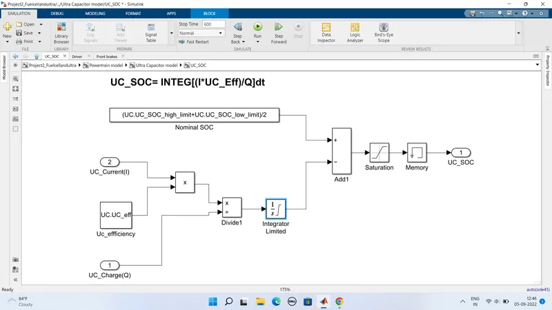
- UC_SOC
UC current
UC_OCV:
UC_Charge:
UC_SOC:
Battery model:
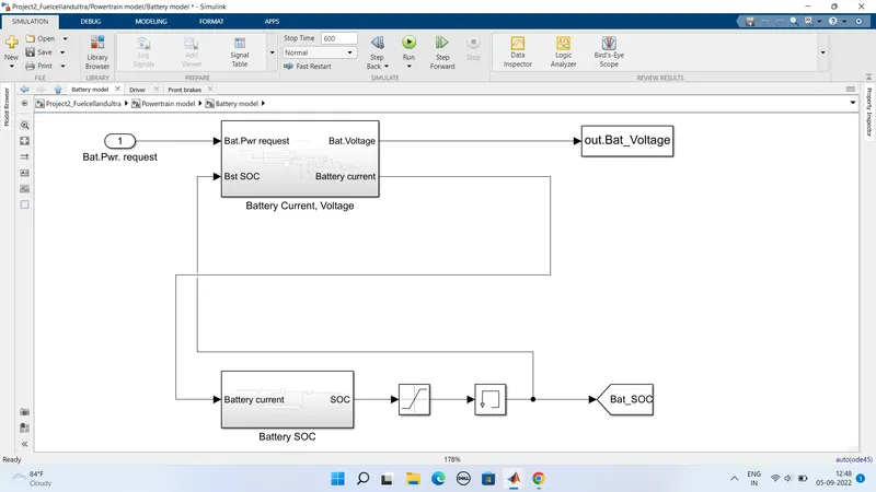
In this subsystem the input as battery power request and from this input we can calculate the battery SOC values battery current voltage values
Two subsystems are :
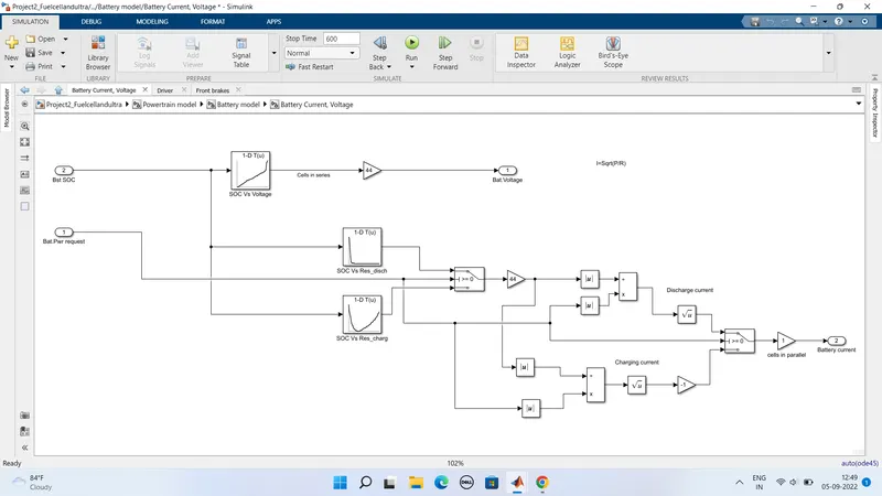
- Battery current,voltage.
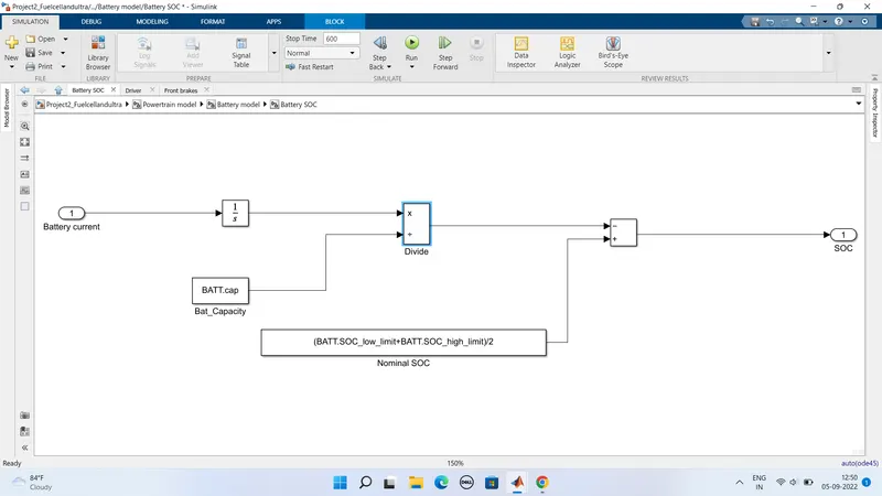
- Battery SOC.
Battery current voltage:
Battery SOC:
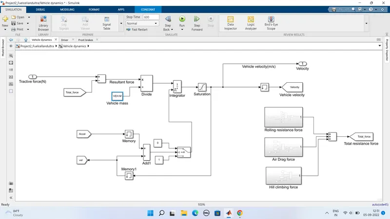
Vehicle dynamics:
-
Here in this subsystem the input is the total traction force of vehicle generated from the power train subsystem
-
So This Total resistance forces from rolling resistance airdrag resistance and hill climbing resistance are get subtracted from the total traction force to get the resultant force.
-
Now The resultant force is divided by mass to get the acceleration values. so This acceleration values are integrated by using integrator block to get the vehicle velocity output
-
So The output from integrator block given to a saturation block to consider the velocity values from 0 to infinity as vehicle velocity output
-
Here The integrator block is get reseted when the vehicle velocity reaches 0
-
So This is done because as we are using integrator block it produces a integral windup
-
The Integral windup means when the actual velocity tends to make match with desired velocity some times a shoot up of corrected signal occurs which again makes next shootdown signal to attain its steady state desired velocity.
-
So To avoid this situation when the vehicle velocity gets to zero the integrator block should get reseted
-
Then This makes the integrator to start the action again from initial state after the vehicle move from its rest condition
-
So This action will avoid the windup situations.This can be acheived in model by verifying acceleration and velocity signals as reaching to Zero velocity
-
Now When the acceleration signal crosses 0 means the output from memory block is 0 as memory block output is precious input.Its makes a step delay As same for velocity signal crosses 0 means the output from memory block becomes 0.
-
Now Both values are summed up and given to a switch condition.
-
Now If summed up values is above 0 satisfying the switch condition.
-
Thus makes no resetting of integrator for positive values.
-
Or If summed up value gets 0 the switch condition fails.
-
Thus makes the integrator to reset
Rolling resistance force:
Airdrag resistance force:
Hill climbing resistance force:
At last loading the parameters in workspace
Output results:
Desired velocity Vs Actual vehicle velocity:
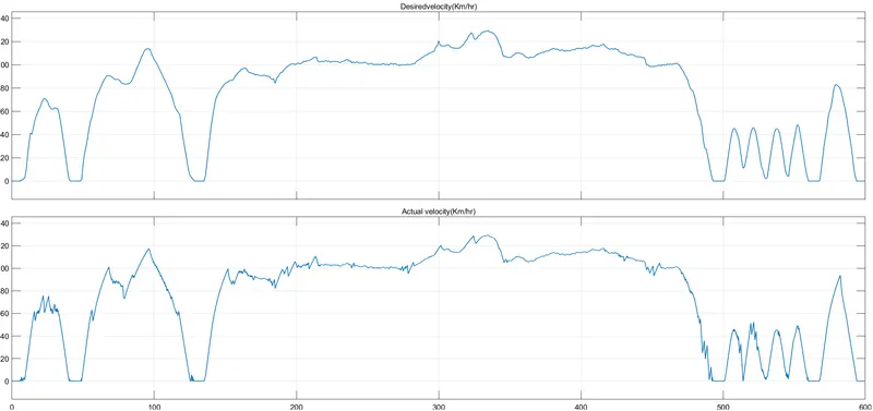
Here From the plot we can understand that both desired and actual velocity of vehicle are controlled and matched
Power sharing output:
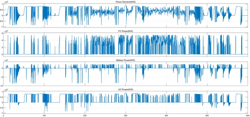
- Here From the above plot we can see the sharing of total power request among the Battery UC and Fuel cell
- The power demand of above 55KW are acheived by the ultra capacitor
- The power demand of 0-23KW are acheived by battery
- And the power demand from above 23 KW upto 55 KW is acheived from Fuel cell.
Conclusion :
we have Run the simulation changed the threshold and created plots and measure current and hydrogen consumption. anf Specifyed the outputs.